EP1497066B1 - Moyens de transmission pour un dispositif de coupe - Google Patents
Moyens de transmission pour un dispositif de coupe Download PDFInfo
- Publication number
- EP1497066B1 EP1497066B1 EP03746279A EP03746279A EP1497066B1 EP 1497066 B1 EP1497066 B1 EP 1497066B1 EP 03746279 A EP03746279 A EP 03746279A EP 03746279 A EP03746279 A EP 03746279A EP 1497066 B1 EP1497066 B1 EP 1497066B1
- Authority
- EP
- European Patent Office
- Prior art keywords
- cutting
- cutting unit
- striking lever
- hammer
- lever
- Prior art date
- Legal status (The legal status is an assumption and is not a legal conclusion. Google has not performed a legal analysis and makes no representation as to the accuracy of the status listed.)
- Expired - Lifetime
Links
- 238000005520 cutting process Methods 0.000 title claims abstract description 146
- 230000033001 locomotion Effects 0.000 claims abstract description 23
- 230000007246 mechanism Effects 0.000 claims description 18
- 230000005540 biological transmission Effects 0.000 claims description 9
- 238000004146 energy storage Methods 0.000 claims description 4
- 238000003825 pressing Methods 0.000 claims description 4
- 238000009434 installation Methods 0.000 claims description 3
- 238000003860 storage Methods 0.000 claims description 2
- 230000003028 elevating effect Effects 0.000 claims 2
- 230000004075 alteration Effects 0.000 claims 1
- 238000004080 punching Methods 0.000 description 36
- 238000000034 method Methods 0.000 description 7
- 230000008569 process Effects 0.000 description 7
- 238000009527 percussion Methods 0.000 description 6
- 239000002184 metal Substances 0.000 description 4
- 230000008878 coupling Effects 0.000 description 3
- 238000010168 coupling process Methods 0.000 description 3
- 238000005859 coupling reaction Methods 0.000 description 3
- 238000000926 separation method Methods 0.000 description 3
- 230000008859 change Effects 0.000 description 2
- 238000013461 design Methods 0.000 description 2
- 238000011161 development Methods 0.000 description 2
- 230000018109 developmental process Effects 0.000 description 2
- 230000001360 synchronised effect Effects 0.000 description 2
- 230000008901 benefit Effects 0.000 description 1
- 238000006243 chemical reaction Methods 0.000 description 1
- 230000006835 compression Effects 0.000 description 1
- 238000007906 compression Methods 0.000 description 1
- 238000006073 displacement reaction Methods 0.000 description 1
- 230000002996 emotional effect Effects 0.000 description 1
- 230000006870 function Effects 0.000 description 1
- 239000007788 liquid Substances 0.000 description 1
- 238000004519 manufacturing process Methods 0.000 description 1
- 238000012986 modification Methods 0.000 description 1
- 230000004048 modification Effects 0.000 description 1
- 238000009740 moulding (composite fabrication) Methods 0.000 description 1
- 230000000284 resting effect Effects 0.000 description 1
- 238000005245 sintering Methods 0.000 description 1
- 238000012546 transfer Methods 0.000 description 1
- 230000009466 transformation Effects 0.000 description 1
- 230000001960 triggered effect Effects 0.000 description 1
- 238000011144 upstream manufacturing Methods 0.000 description 1
Images


Classifications
-
- B—PERFORMING OPERATIONS; TRANSPORTING
- B30—PRESSES
- B30B—PRESSES IN GENERAL
- B30B1/00—Presses, using a press ram, characterised by the features of the drive therefor, pressure being transmitted directly, or through simple thrust or tension members only, to the press ram or platen
- B30B1/02—Presses, using a press ram, characterised by the features of the drive therefor, pressure being transmitted directly, or through simple thrust or tension members only, to the press ram or platen by lever mechanism
-
- B—PERFORMING OPERATIONS; TRANSPORTING
- B23—MACHINE TOOLS; METAL-WORKING NOT OTHERWISE PROVIDED FOR
- B23D—PLANING; SLOTTING; SHEARING; BROACHING; SAWING; FILING; SCRAPING; LIKE OPERATIONS FOR WORKING METAL BY REMOVING MATERIAL, NOT OTHERWISE PROVIDED FOR
- B23D15/00—Shearing machines or shearing devices cutting by blades which move parallel to themselves
- B23D15/12—Shearing machines or shearing devices cutting by blades which move parallel to themselves characterised by drives or gearings therefor
-
- B—PERFORMING OPERATIONS; TRANSPORTING
- B23—MACHINE TOOLS; METAL-WORKING NOT OTHERWISE PROVIDED FOR
- B23D—PLANING; SLOTTING; SHEARING; BROACHING; SAWING; FILING; SCRAPING; LIKE OPERATIONS FOR WORKING METAL BY REMOVING MATERIAL, NOT OTHERWISE PROVIDED FOR
- B23D23/00—Machines or devices for shearing or cutting profiled stock
-
- B—PERFORMING OPERATIONS; TRANSPORTING
- B23—MACHINE TOOLS; METAL-WORKING NOT OTHERWISE PROVIDED FOR
- B23D—PLANING; SLOTTING; SHEARING; BROACHING; SAWING; FILING; SCRAPING; LIKE OPERATIONS FOR WORKING METAL BY REMOVING MATERIAL, NOT OTHERWISE PROVIDED FOR
- B23D35/00—Tools for shearing machines or shearing devices; Holders or chucks for shearing tools
- B23D35/008—Means for changing the cutting members
Definitions
- the invention relates to a cutting device for cutting a workpiece by means of a movable cutting element, wherein the cutting element for driving a lifting movement via drive means is driven by a drive and the drive means reach a maximum lifting speed V 1 .
- Fast-running punching and cutting machines are usually designed as eccentric presses, with which separation, punching, sintering and forming operations of metallic parts and profiles are performed.
- the aim is to achieve the highest possible output of cut or stamped metal parts.
- the cutting surfaces generated during the cutting or punching process often have to meet high demands with regard to the evenness or the orientation of the cut surfaces that is as vertical as possible.
- High-speed shear cutting process also called high-speed impact cutting (HSIC).
- HSIC high-speed impact cutting
- the special feature of the HSIC process is that the separation or punching process is accompanied by no significant heat losses.
- the kinetic energy of a punching or cutting element is converted into transformation energy with almost no loss of heat (adiabatic). This has the consequence that the severed parts are essentially free of burrs and that the cut surfaces have a minimum of smooth cut in relation to the fracture surface exhibit.
- the mentioned increase in cutting speed is a prerequisite for maximum application rates.
- a drive device for a high-speed punching and cutting press known.
- a plunger is driven, which carries a cutting punch, which separates by punching cutting or punching parts of a metal strip.
- the plunger is driven by a drive means with a respective disk-shaped crank and a coupling, and has during a part of its stroke on an opposite in a drive with conventional storage increased speed.
- a disadvantage of this known solution is that the punching or cutting machines must be laboriously modified. On the one hand, this can be difficult for installation space reasons and, on the other hand, it requires a great deal of time.
- the high conversion effort prevents a quick and flexible change between cutting or punching operations with conventional cutting speeds and with adiabatic cutting speeds.
- the present invention is therefore based on the object to provide a cutting device, with no complicated modifications to the punching and cutting machines excellent cut quality is achieved with increased application rates.
- the drive means on a lifting plate which is fixedly connected to a Pressenbär the punching and cutting machine, wherein the cutting device has a support plate which is fixedly connected to a press table of the punching and cutting machine.
- the cutting device is provided as an additional module for installation in commercial punching and cutting machines.
- the cutting device can be offered as an accessory or retrofit for already in use punching and cutting machines or offered as an additional equipment for new punching and cutting machines.
- the machines, especially their drive, do not have to be adapted to switch between a use with normal or adiabatic cutting speeds.
- the cutting device according to the invention has the significant advantage that high cutting or lifting speeds can be achieved without the punching or cutting machines have to be adapted consuming.
- the transmission means are provided separately and cause the maximum lifting speed V 1 predetermined by the drive means to be increased to a maximum lifting speed V 2 .
- the lifting speed V 2 is in the range of 2.5 to 3.5 m / sec.
- the cutting device according to the invention can be easily installed in high-speed punching or cutting machines.
- a maximum lifting speed V 1 is achieved in its 90 ° position, ie exactly between the TDC or TDC position.
- This lifting speed V 1 is inventively about Gear means increased to a maximum lifting speed V 2 > V 1 .
- the carrier plate is used to attach elements of the cutting device, such as a stationary die for receiving a workpiece or the abutment described above.
- the die and the stop can be releasably secured to the carrier plate, whereby a modular design is guaranteed to edit various sheet metal profiles can.
- the carrier plate can be prepared externally for its use in the punching or cutting machine and then placed on the press table of the machine and connected to this example, via terminals.
- the drive means have a lifting plate. At this one or more plunger and the return element can be attached. Preferably, the mounting position of the plunger or the plunger on the lifting plate is adjustable so that desired ratios of the lifting speed V 2 can be generated to the lifting speed V 1 .
- the lifting plate outside the cutting or punching machine can be prepared for their use. Subsequently, the lifting plate can be connected, for example via clamping means with the Pressenbär.
- the transmission means comprise a hammer.
- the gear means have a plunger for driving the hammer.
- the arrangement of percussion lever and one or more plungers can be realized in a particularly simple manner, a lever principle.
- the plunger is at a speed V 1 corresponding to the speed of the drive means emotional.
- the plunger presses on a portion of the percussion lever, wherein plunger and hammer are not rigidly connected to each other, so that the hammer in the areas spaced from the plunger areas relative to the lifting speed V 1 has increased speeds.
- the region of the impact lever, with which a striking contact is made on a cutting element has a relative to the lifting speed V 1 increased lifting speed V 2 .
- the gear ratio can be adjusted, with the speed V 1 is increased to the speed V 2 .
- the plunger has a spring element.
- the spring element is designed to be particularly rigid. This means that the spring constant is so high that a pressure transmission from the drive means via the plunger to the hammer is possible and the kinetic energy required for cutting or punching can be transferred to the hammer.
- the spring it is possible to stop the movement of the hammer from one of the 90 ° position of a crank drive corresponding position while ensuring the drive of the crank mechanism from the 90 ° position over the 180 ° position and back in the return direction.
- the hammer on a double-projecting transverse pin can serve, for example, for the plunger to be produced a directed to the workpiece movement of the hammer presses on the protruding part of the transverse pin.
- the transverse bolt can serve, for example, for the plunger to be produced a directed to the workpiece movement of the hammer presses on the protruding part of the transverse pin.
- a stop for the hammer or the transverse bolt is provided.
- the stop causes the percussion lever at the beginning of the cutting or punching process, for example, can transmit its kinetic energy to a cutting punch and is then stopped by contact of the hammer with the stop, so that further swinging of the percussion lever is prevented.
- a further embodiment provides that the stop is elastically yielding or has an elastically yielding stop surface. It may also be the impact lever elastically deflectable or deformable. As a result, the impact pulse is transmitted to the cutting tool in such a way that the lever arm is caught by the stop already shortly before hitting the actual cutting tool. As a result, either the inherent elasticity of the impact arm is used for the remaining distance or a device integrated in the stop is used. This ensures that the impact pulse acts on the workpiece in a very short time and a nearly complete transfer of energy takes place with high efficiency.
- a development of the invention provides that a return element is provided for producing a workpiece directed away movement of the hammer.
- Punching be brought into its resting or starting position. From this position, the hammer can be accelerated by the above-mentioned plunger back to the lifting speed V 2 .
- the return element on a slot which is penetrated by the cross bolt.
- the slot allows that when the transverse pin in an end position in the slot of the hammer can be moved.
- the return element and the hammer are decoupled from each other during the lifting movement of the drive means in crank positions between 90 ° and 270 °. As a result, a swinging of the drive means is made possible after the cutting or punching process, wherein the hammer can come to rest on the stop described above.
- the hammer on the support plate or at least indirectly connected to the support plate holding elements is pivotally articulated.
- This pivot bearing can be formed by a hinge pin and serves the position definition of the hammer.
- the hammer can be fixed, for example by means of a hinge pin directly to the support plate or on holding elements, which are provided on the support plate.
- Such a holding element can be formed for example by a bearing block.
- the plunger is arranged with respect to the longitudinal extension of the percussion lever between the articulation and the cutting element.
- the drive of the hammer can also be done in a section located outside of the section between linkage and cutting element. As a result, a reversal of the stroke direction is generated.
- An embodiment of the invention provides that the lifting plate is movable relative to the carrier plate and guided by guide means.
- the guide means which can be provided for example in the form of columns, a precise drive of the hammer is guaranteed. As a result, a consistently high cut surface quality can be generated.
- the drive means on a crank mechanism is available in commercial punching and cutting machines and has proven to be reliable.
- a maximum lifting speed V 1 is achieved at a crank position of 90 °.
- a feed device for tracking the workpiece is provided.
- Such a feed device is synchronized with the drive for generating the lifting movement of the cutting or punching machine, so that the workpiece between two strokes is tracked by exactly one product length.
- the drive is an electric, hydraulic, pneumatic, pyrotechnic or magnetic drive.
- the cutting device according to the invention is universally applicable.
- the drive has an energy store.
- the energy store can be prestressed or recharged by the drive, and the stored energy can be abruptly delivered to the drive means.
- the drive for example, a spring or a gas pressure accumulator.
- the necessary for the function of the device impact energy and the impact velocity can also be guaranteed if the actual drive does not have this speed.
- the energy is stored for example in a resilient element by this biased. By loosening a Klink or Locking mechanism releases this stored energy in a very short time and then has the required parameters.
- the spring accumulator can be either a mechanical spring (made of wire or a spring plate) or operated with a gaseous or liquid medium.
- the cutting device according to the invention is designed as a quick-change cassette.
- the adaptability of the cutting device according to the invention to different workpieces or their sizes is achieved in that the impact energy e.g. is adjustable by lever length change, by moving masses and / or by different bias of spring elements. Furthermore, the impact energy can be infinitely or in stages adjustable.
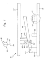
- Fig. 1 shows a generally designated by the reference numeral 10 cutting device, which is driven by a crank drive 20 shown symbolically.
- the crank mechanism 20 consists of a drive pulley 22, which is driven by means not shown in detail, and an eccentrically to the center of the drive pulley 22 hinged coupling 24.
- the drive pulley 22 is driven in the direction of rotation 26 in a clockwise direction.
- the coupling 24 is shown symbolically connected to the Pressenbär 28 a punching or cutting machine, not shown.
- the cutting device 10 has two mutually substantially parallel plates.
- a bearing block 36 On the support plate 34, the following elements are attached: A bearing block 36, a stopper 38 and a die 40.
- the bearing block 36 has an opening into which a hinge pin 42 is inserted.
- the hinge pin 42 forms a pivot bearing for a pivotable about the hinge pin 42 hammer 44.
- the hammer 44 is shown in Fig. 1 in an initial position corresponding to the 0 ° position of the crank mechanism 20.
- the plunger 46 is designed as a spring with a very high spring constant and connected via a symbolically shown joint 50 with the hammer 44.
- the hammer 44 is driven by the crank mechanism 20, by the movement of the press rod 28 and the lifting plate 32, as well as by the movement of the plunger 46 and the hinge 50, i. pivoted about the hinge pin 42 around.
- the hammer 44 has a transverse pin 52 which extends through the hammer 44 therethrough. The free end of the transverse pin 52 engages in a slot 54 of a return member 48 secured to the lifting plate 32.
- the slot 54 extends in a direction perpendicular to the plane of the lifting plate 32 direction. It has a transverse extent 56, which is slightly larger than the diameter of the transverse pin 52.
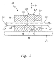
- the die 40 consists of a stationary die entrance 58 and a stationary die exit 60.
- the die 40 also has a Cutting punch 62 which is disposed between the die inlet 58 and the die exit 60 and is suitable for designated by reference numeral 64 lifting or scrubhubterrorismen.
- the die inlet 58, the cutting punch 62 and the die exit 60 have coaxial with a common axis 66 arranged openings 68, 70 and 72, respectively.
- the workpiece 74 to be machined has the said central axis 66 and is guided in the opening 68 of the die entrance 58 and in the opening 70 of the cutting punch 62 with a clearance fit.
- the opening 72 of the die exit 60 has a larger diameter than the workpiece 74.
- Fig. 2 is a dashed lines, perpendicular to the axis 66 extending cutting plane 76 can be seen along which a cut portion 74 'of a workpiece supply 74' 'can be separated.
- the separation or cutting process is triggered by a lifting movement of the cutting punch 62 from the position shown in Fig. 2 in the direction of the support plate 34.
- Such movement as shown below, by the impact of the hammer 44 shown in FIG generates the cutting punch 62.
- the edge 78 acts as a cutting edge.
- the cutting punch 62 can be brought from its working position into the rest position shown by means of a return element in the form of a spring 80 following a cutting operation shown below.
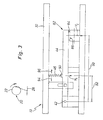
- the cutting operation is described, which takes place substantially in the 90 ° position of the crank drive 20 and the drive pulley 22.
- this position of the crank mechanism 20 is driven by Pressenbär 28 lifting plate 32 in a position opposite to the position shown in Fig. 1 lower position.
- About the plunger 46 and the hinge 50 is a movement and power transmission to the punch 44.
- the punch 44 has at its end remote from the hinge pin 42 an impact area 82 84 on.
- the impact area 84 strikes its striking surface 86 on a face 88 of the cutting punch 62 (see Fig. 2). Impact of the impact surface 86 on the striking surface 88 causes the cutting punch 62 to dip between the die entrance 58 and the die exit 60.
- the speed at which the impact area 84 impacts the cutting punch 62 is designated V 2 in FIG.
- the speed V 2 is increased relative to the speed V 1 of the plunger 46, which is predetermined by the movement of the crank mechanism 20 or the press rod 28, the lifting plate 32 and the plunger 46.
- the speed ratio V 2 to V 1 corresponds to the ratio shown in Fig. 3 from the distance 90 between the hinge pin 42 and center of the impact area 84 to the distance 92 between the hinge pin 42 and the position of the plunger 46.
- By changing the position of the plunger 46 can more Gear ratios are set.
- the ratio of V 2 to V 1 is increased, with displacement of the plunger 46 in the direction 96, the transmission ratio of V 2 to V 1 is reduced.
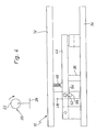
- the position of the cutting device 10 will be described, which assumes this in the 180 ° position of the crank mechanism 20 and the drive pulley 22.
- the driven by Pressenbär 28 lifting plate 32 is located opposite to the position shown in Fig. 3 closer to the support plate 34, in the lower working position.
- the hammer 44 rests on the stop 38 and is decoupled from the movement of the lifting plate 32 by the compression of the spring tappet 46.
- the fixedly connected to the lifting plate 32 return member 48 may move together with the lifting plate 32 down, since the transverse pin 52 is guided in the slot 54 of the return member 48.
- the hammer 44 can be moved back from the position shown in Fig. 4 in the initial position shown in Fig. 1. After inserting the return stroke of Pressenbärs 28 (from crank position 180 °) and thus the lifting plate 32 and the remindholelements 48 of the transverse pin 52 comes in a contact area 98 of the slot 54 to the plant (immediately before crank position 270 °). Thus, hammer 44 is lifted back on further movement of the crank mechanism 20 in the initial position shown in FIG.
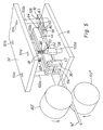
- Fig. 5 shows a perspective view of an embodiment of a cutting device.
- This comprises an upper lifting plate 32 which is fixedly connected to the Pressenbär a punching or cutting machine, not shown.
- the cutting device also comprises a parallel to the lifting plate 32 support plate 34 which is fixedly connected to the press table of a punching or cutting machine, not shown.
- On the support plate 34 four vertically upstanding columns 100a-d are attached.
- the lifting plate 32 parallel to the support plate 34 has cylindrical openings 101a-d in which the columns 100a-d are slidably guided.
- the column arrangement ensures a high rigidity of the cutting device and an exact guidance of the lifting plate 32.
- a bearing block 36 can be seen, in which a hinge pin 42 is inserted, which serves as a pivot bearing for a hammer 44. Furthermore, a stop 38 is provided on the support plate 34, on which in the position of the hammer lever 44 shown in FIG. 5 rests a transverse pin 52 inserted therein.
- the impact lever 44 has an impact area 84, which meets in its working position on a punch 62 which is arranged parallel to the extension direction of the guide columns 100a-d displaceable between a stationary die inlet 58 and a stationary die exit 60. Below the impact punch 62, the spring element 80 shown in FIG. 2 can be seen.
- the hammer 44 is driven by two spring tappets 46 'and 46 "with the interposition of joints 50, by pressing the spring plate 46', 46" firmly pressed against the lifting plate 32 on the laterally projecting out of the hammer free ends of the transverse pin 52.
- the impact lever 44 can be lifted from its work position shown in FIG. 5 into a rest or initial position corresponding to the illustration in FIG.
- a return element 48 is provided which raises the impact lever 44 from the work position shown in Fig. 5 in a rest position at a central region of the transverse pin 52 by abutment of an edge region of a long hole, not shown in Fig. 5.
- a feed device upstream of the cutting device is provided for tracking the workpiece supply 74 ", which consists of two feed rollers 102 'and 102" rotating in opposite directions of rotation.
- the rollers 102', 102 " are driven by a motor (not shown) driven, which is synchronized with the drive of the punching and cutting machine, so that each cutting or punching process exactly one workpiece length of the workpiece supply 74 '' is tracked.
- the workpiece supply 74 is fed to the die inlet 58 and the cutting punch 62 by a guide element 104 arranged in the bearing block 36.
- FIG. 6 shows a schematic representation of the cutting device 10 with elastic stop 38.
- the stop 38 can be designed to be elastic in itself or it can, as shown in the drawing, be provided with an elastically resilient stop surface 108. It also clearly recognizes that in the rest position of the hammer 44, a small gap 110 exists between the free end of the hammer 44 and the die 40.
- FIG. 7 shows a schematic representation of the cutting device 10 with elastic striking arm 44, which swings so far in the direction of the double arrow 112 that it closes the gap 110 and abuts against the die 40.
- FIG. 8 shows a schematic representation of the cutting device 10 with a drive with spring accumulator 114, which is arranged below the end 116 of the percussion lever 44.
- the spring accumulator 114 is charged and abruptly in Direction of the arrow 118 relaxes. In this way it is ensured that the necessary energy is provided and that the energy is released quickly.
- FIG. 8 Also shown in Fig. 8 is a second variant of an energy storage 114 'located axially behind the hammer 44 and which may be e.g. from a force acting in the direction of the arrow 120 force is rechargeable. The energy is released by swinging out a lever 122 which strikes a projection 124 at the free end 116 of the hammer 44. Both the energy storage 114 and 114 'can be charged with a small force and slowly. The energy is delivered abruptly, so that the die 40 is acted upon by the hammer 44 at a speed of> 4 m / s.
Landscapes
- Engineering & Computer Science (AREA)
- Mechanical Engineering (AREA)
- Press Drives And Press Lines (AREA)
- Crushing And Pulverization Processes (AREA)
- Perforating, Stamping-Out Or Severing By Means Other Than Cutting (AREA)
- Control Of Cutting Processes (AREA)
- Threshing Machine Elements (AREA)
- Harvester Elements (AREA)
Claims (23)
- Dispositif de coupe (10) destiné à couper une pièce (74) au moyen d'un élément de coupe mobile (62), dans lequel l'élément de coupe (62) peut être entraîné par un mécanisme d'entraînement par l'intermédiaire de moyens d'entraînement (20, 22, 24, 28, 32) afin d'exécuter un mouvement de levage, les moyens d'entraînement (20, 22, 24, 28, 32) pouvant atteindre une vitesse de levage maximale v1, dans lequel sont prévus des moyens de transmission (44, 46), par l'intermédiaire desquels l'élément de coupe (62) peut être déplacé avec une vitesse de levage maximale v2 > v1 et en ce que le dispositif de coupe (10) est prévu en tant que module supplémentaire pour montage dans des machines à estamper et couper usuelles, caractérisé en ce que les moyens d'entraînement (20, 22, 24, 28, 32) comportent une plaque de levage (32) pouvant être raccordée fermement à un marteau à enfoncer (28) de la machine à estamper et couper dans lequel le dispositif de coupe (10) comporte une plaque de support (34) pouvant être raccordé fermement à une table de presse de la machine à estamper et couper.
- Dispositif de coupe (10) selon revendication 1, caractérisé en ce que les moyens de transmission (44, 46) comportent un bras à battements (44).
- Dispositif de coupe (10) selon l'une des revendications précédentes, caractérisé en ce que les moyens de transmission (44, 46) comportent un poussoir (46) pour entraîner le bras à battements (44).
- Dispositif de coupe (10) selon revendication 3, caractérisé en ce que le poussoir (46) comporte un élément ressort.
- Dispositif de coupe (10) selon revendication 3 ou 4, caractérisé en ce que le bras à battements (44) comporte une goupille transversale (52) débordant des deux côtés.
- Dispositif de coupe (10) selon revendication 5, caractérisé en ce le poussoir (46) appuie sur la goupille transversale (52) afin de générer un mouvement du bras à battements (44) orienté vers la pièce (74).
- Dispositif de coupe (10) selon l'une des revendications 2 à 6, caractérisé en ce qu'une butée (38) est prévue pour le bras à battements (44) ou la goupille transversale (52).
- Dispositif de coupe (10) selon revendication 7, caractérisé en ce que la butée (38) est élastiquement flexible.
- Dispositif de coupe (10) selon les revendications 7 ou 8, caractérisé en ce que la butée (38) dispose d'une surface à enfoncer élastiquement flexible.
- Dispositif de coupe (10) selon l'une des revendications 2 à 9, caractérisé en ce qu' un élément de rappel (48) est prévu pour générer un mouvement du bras à battements (44) éloignant celui-ci de la pièce (74).
- Dispositif de coupe (10) selon revendication 10, caractérisé en ce que l'élément de rappel (48) comporte un trou oblong (54) traversé par la goupille transversale (52).
- Dispositif de coupe (10) selon revendication 11, caractérisé en ce que le bras à battements (44) est articulé pivotant sur la plaque de support (34) ou sur des éléments de fixation (36, 42) qui sont, au moins indirectement, liés à la plaque de support.
- Dispositif de coupe (10) selon revendication 12, caractérisé en ce que le poussoir (46) est, par rapport à l'étendue longitudinale du bras à battements (44), disposé entre l'articulation de celui-ci (42) et l'élément de coupe (62).
- Dispositif de coupe (10) selon l'une des revendications précédentes, caractérisé en ce que la plaque de levage (32) peut être déplacée par rapport à la plaque de support (34) et est guidée par des éléments de guidage.
- Dispositif de coupe (10) selon l'une des revendications précédentes, caractérisé en ce que les moyens d'entraînement (20, 22, 24, 28, 32) comportent un mécanisme d'embiellage (22, 24).
- Dispositif de coupe (10) selon l'une des revendications précédentes, caractérisé en ce qu'un dispositif d'avance est prévu pour amener la pièce.
- Dispositif de coupe (10) selon l'une des revendications précédentes, caractérisé en ce que le mécanisme d'entraînement comporte un accumulateur d'énergie.
- Dispositif de coupe (10) selon revendication 17, caractérisé en ce que l'accumulateur d'énergie peut être tendu ou chargé par le mécanisme d'entraînement et que l'énergie accumulée peut être transférée d'un coup aux moyens d'entraînement (20, 22, 24, 28, 32).
- Dispositif de coupe (10) selon l'une des revendications précédentes, caractérisé en ce que le mécanisme d'entraînement comporte un ressort ou un accumulateur-pneumatique.
- Dispositif de coupe (10) selon l'une des revendications 2 à 19, caractérisé en ce que le bras à battements (44) est fléchissable ou déformable élastiquement.
- Dispositif de coupe (10) selon l'une des revendications précédentes, caractérisé en ce qu'il est conçu sous forme d'une cassette à changement rapide.
- Dispositif de coupe (10) selon l'une des revendications précédentes, caractérisé en ce que l'énergie de frappe peut être réglée par modification de la longueur du bras à battements, par le déplacement de masses et/ou par des tensions différentes d'éléments ressort.
- Dispositif de coupe (10) selon revendication 22, caractérisé en ce que l'énergie de frappe peut être réglée en continu ou par paliers.
Applications Claiming Priority (3)
| Application Number | Priority Date | Filing Date | Title |
|---|---|---|---|
| DE10217026 | 2002-04-12 | ||
| DE10217026A DE10217026C1 (de) | 2002-04-12 | 2002-04-12 | Schneideinrichtung |
| PCT/EP2003/003114 WO2003086691A1 (fr) | 2002-04-12 | 2003-03-26 | Moyens de transmission pour un dispositif de coupe |
Publications (2)
| Publication Number | Publication Date |
|---|---|
| EP1497066A1 EP1497066A1 (fr) | 2005-01-19 |
| EP1497066B1 true EP1497066B1 (fr) | 2007-11-07 |
Family
ID=29224523
Family Applications (1)
| Application Number | Title | Priority Date | Filing Date |
|---|---|---|---|
| EP03746279A Expired - Lifetime EP1497066B1 (fr) | 2002-04-12 | 2003-03-26 | Moyens de transmission pour un dispositif de coupe |
Country Status (5)
| Country | Link |
|---|---|
| EP (1) | EP1497066B1 (fr) |
| AT (1) | ATE377474T1 (fr) |
| AU (1) | AU2003226711A1 (fr) |
| DE (2) | DE10217026C1 (fr) |
| WO (1) | WO2003086691A1 (fr) |
Cited By (1)
| Publication number | Priority date | Publication date | Assignee | Title |
|---|---|---|---|---|
| CN103586529A (zh) * | 2013-10-30 | 2014-02-19 | 安徽奇峰机械装备有限公司 | 一种冲压式切割机 |
Families Citing this family (6)
| Publication number | Priority date | Publication date | Assignee | Title |
|---|---|---|---|---|
| DE102004043189B3 (de) * | 2004-09-03 | 2005-08-25 | Msa Maschinenbau - Service - Automatisierungstechnik Gmbh | Schneidpresse |
| DE102004049149A1 (de) * | 2004-10-07 | 2006-04-13 | Feintool International Management Ag | Verfahren und Vorrichtung zum Herstellen und/oder Bearbeitung von Teilen |
| DE102006031890B4 (de) * | 2006-07-07 | 2014-01-16 | Maschinenbau-Service-Automatisierungstechnik Chemnitz GmbH | Einrichtung zum gewichtsgenauen Ablängen von Stangenabschnitten und Verfahren zur Ermittlung der Schlagenergie |
| CN107971385A (zh) * | 2017-12-26 | 2018-05-01 | 昆山诚业德通讯科技有限公司 | 一种异频推杆及异频切割装置 |
| CN108526570B (zh) * | 2018-05-03 | 2020-01-24 | 南通密特尔机床制造有限公司 | 一种处理多个板材的裁切设备 |
| CN111219390A (zh) * | 2020-02-25 | 2020-06-02 | 江苏科瑞恩自动化科技有限公司 | 一种可迭代通用保压装置 |
Family Cites Families (20)
| Publication number | Priority date | Publication date | Assignee | Title |
|---|---|---|---|---|
| FR585866A (fr) * | 1925-03-09 | |||
| FR959271A (fr) * | 1950-03-28 | |||
| FR504081A (fr) * | 1919-09-01 | 1920-06-24 | Jean Andreu | Martinet pour le planage des métaux en feuilles |
| CH91942A (de) * | 1921-01-04 | 1922-02-01 | G Guedel | Hebelhammer. |
| DE512995C (de) * | 1929-02-13 | 1930-11-20 | Alexis Bouchet | Mechanisches Hammerwerk |
| GB437267A (en) * | 1933-03-27 | 1935-10-24 | Robert Rex Downie | Improvements in or relating to power hammers |
| DE700582C (de) * | 1935-04-24 | 1940-12-23 | Adam Parjanen | An eine Handbohrmaschine ansetzbares hammerartiges Schlaggeraet |
| FR1044384A (fr) * | 1951-11-02 | 1953-11-17 | Cisaille à moteur | |
| FR1083817A (fr) * | 1953-09-18 | 1955-01-12 | Cisaille à placages comportant une lame de cisaille animée mécaniquement d'un mouvement de va-et-vient vertical par un entraînement à manivelle | |
| US3408888A (en) * | 1965-09-17 | 1968-11-05 | Buffalo Forge Co | Shearing apparatus |
| GB1423723A (en) * | 1973-03-23 | 1976-02-04 | Warnke Umformtech Veb K | Tool arrangement for the periodic shearing of predetermined lengths of corrugated plates produced continuously from a sheet metal strip by means of intermittently operating shaping tools |
| FR2278440A1 (fr) * | 1974-02-07 | 1976-02-13 | Promecan Sisson Lehmann | Cisaille oscillante |
| IT1107521B (it) * | 1978-04-13 | 1985-11-25 | Montoli Ezio | Cinematismo a leva,realizzante due condizioni distinte di vantaggio,particolarmente da utilizzare a corredo di macchine utensili,particolarmente per il taglio di pietre naturali e artificiali |
| US4337679A (en) * | 1979-07-02 | 1982-07-06 | Krylov Gleb L | Plate shears |
| DE3816739A1 (de) * | 1988-05-17 | 1989-11-30 | Manfred Wanzke | Stanzwerkzeug zum einlegen zwischen stoessel und aufspannplatte einer presse |
| US5195415A (en) * | 1992-01-24 | 1993-03-23 | Sweed Machinery, Inc. | Apparatus for cutting elongate pieces |
| AU663362B2 (en) * | 1992-03-26 | 1995-10-05 | Vergola Pty Ltd | Improved cut-off means |
| JPH10113816A (ja) * | 1996-10-09 | 1998-05-06 | Sakai Pipe Kogyo:Kk | 開先加工方法および開先加工装置 |
| DE19722245A1 (de) * | 1997-05-28 | 1998-12-03 | Schuler Pressen Gmbh & Co | Antriebseinrichtung für eine schnellaufende Stanz- und Schneidpresse |
| DE19928841C1 (de) * | 1999-06-24 | 2001-01-18 | Heinz Schwarz Gmbh & Co Kg | Schneidvorrichtung für Bleche |
-
2002
- 2002-04-12 DE DE10217026A patent/DE10217026C1/de not_active Expired - Fee Related
-
2003
- 2003-03-26 WO PCT/EP2003/003114 patent/WO2003086691A1/fr not_active Ceased
- 2003-03-26 AU AU2003226711A patent/AU2003226711A1/en not_active Abandoned
- 2003-03-26 EP EP03746279A patent/EP1497066B1/fr not_active Expired - Lifetime
- 2003-03-26 AT AT03746279T patent/ATE377474T1/de not_active IP Right Cessation
- 2003-03-26 DE DE50308542T patent/DE50308542D1/de not_active Expired - Lifetime
Cited By (2)
| Publication number | Priority date | Publication date | Assignee | Title |
|---|---|---|---|---|
| CN103586529A (zh) * | 2013-10-30 | 2014-02-19 | 安徽奇峰机械装备有限公司 | 一种冲压式切割机 |
| CN103586529B (zh) * | 2013-10-30 | 2015-09-30 | 安徽奇峰机械装备有限公司 | 一种冲压式切割机 |
Also Published As
| Publication number | Publication date |
|---|---|
| ATE377474T1 (de) | 2007-11-15 |
| EP1497066A1 (fr) | 2005-01-19 |
| WO2003086691A1 (fr) | 2003-10-23 |
| DE50308542D1 (de) | 2007-12-20 |
| AU2003226711A1 (en) | 2003-10-27 |
| DE10217026C1 (de) | 2003-12-04 |
Similar Documents
| Publication | Publication Date | Title |
|---|---|---|
| DE102007051894B4 (de) | Freigabemechanismus und mit diesem versehenen Richtvorrichtung | |
| DE69605635T2 (de) | Schlaggerät zum Setzen von Nieten und Verfahren zu seiner Anwendung | |
| WO1994003306A1 (fr) | Procede de fixation d'elements en forme de boulons | |
| EP3731997A1 (fr) | Outil hydraulique pour un dispositif de traction et/ou de pressage | |
| WO1995030513A1 (fr) | Dispositif destine a etre utilise dans une presse pour l'amenee d'elements de fixation et leur fixation par pressage dans des pieces | |
| DE2915327C2 (de) | Arbeitsmaschine mit Fingerschutzeinrichtung für das bewegbare Oberwerkzeug | |
| DE19536415C2 (de) | Scherschneidevorrichtung zur Verwendung mit einer Presse | |
| EP1497066B1 (fr) | Moyens de transmission pour un dispositif de coupe | |
| DE2728647A1 (de) | Formteilpresse | |
| DE10300878B4 (de) | Vorrichtung und Verfahren zum Zuführen eines bolzenförmigen Elements zu einer Verarbeitungseinheit | |
| DE10258928A1 (de) | Taumelfügevorrichtung | |
| EP1252010A1 (fr) | Presse | |
| WO1999037419A1 (fr) | Dispositif de sertissage a elements de pression et de serrage | |
| EP0407658B1 (fr) | Dispositif de serrage et de refoulement ou de serrage et de martelage pour le serrage temporaire de pièces en fils métalliques resp. pour le travail de telles pièces | |
| DE1297571B (de) | Stauchwerkzeug fuer eine Presse | |
| EP1350582A2 (fr) | Mécanisme d'éjection au côté matrice dans une presse à un ou multiples étages | |
| DE3021332A1 (de) | Vorrichtung zum verbinden wneigstens zweier bauteile durch ein schnitt-umform-verfahren | |
| DE3206681A1 (de) | Hydraulisch angetriebene schneidemaschine fuer papierbogen od. dgl. | |
| DE3414522C1 (de) | Bolzenschweißgerät | |
| DE102019110011A1 (de) | Setzkopf, Blechpresse oder Setzgerät mit diesem Setzkopf sowie ein Fügeverfahren eines Fügeelements mit dem Setzkopf | |
| EP0351632A2 (fr) | Dispositif d'entraînement pour une machine à découper travaillant par intermittence | |
| DE102007060815B4 (de) | Stichsäge | |
| DE3112810C2 (fr) | ||
| DE3136413C2 (fr) | ||
| EP0980733A1 (fr) | Cisaille de frappe pour des fils ou des barres |
Legal Events
| Date | Code | Title | Description |
|---|---|---|---|
| PUAI | Public reference made under article 153(3) epc to a published international application that has entered the european phase |
Free format text: ORIGINAL CODE: 0009012 |
|
| 17P | Request for examination filed |
Effective date: 20040924 |
|
| AK | Designated contracting states |
Kind code of ref document: A1 Designated state(s): AT BE BG CH CY CZ DE DK EE ES FI FR GB GR HU IE IT LI LU MC NL PT RO SE SI SK TR |
|
| AX | Request for extension of the european patent |
Extension state: AL LT LV MK |
|
| RIN1 | Information on inventor provided before grant (corrected) |
Inventor name: BOENING, MATTHIAS |
|
| GRAP | Despatch of communication of intention to grant a patent |
Free format text: ORIGINAL CODE: EPIDOSNIGR1 |
|
| GRAS | Grant fee paid |
Free format text: ORIGINAL CODE: EPIDOSNIGR3 |
|
| RAP1 | Party data changed (applicant data changed or rights of an application transferred) |
Owner name: IFUTEC INGENIEURBUERO FUER UMFORMTECHNIK GMBH |
|
| GRAA | (expected) grant |
Free format text: ORIGINAL CODE: 0009210 |
|
| AK | Designated contracting states |
Kind code of ref document: B1 Designated state(s): AT BE BG CH CY CZ DE DK EE ES FI FR GB GR HU IE IT LI LU MC NL PT RO SE SI SK TR |
|
| REG | Reference to a national code |
Ref country code: GB Ref legal event code: FG4D Free format text: NOT ENGLISH |
|
| REG | Reference to a national code |
Ref country code: IE Ref legal event code: FG4D Free format text: LANGUAGE OF EP DOCUMENT: GERMAN |
|
| REG | Reference to a national code |
Ref country code: CH Ref legal event code: EP |
|
| REF | Corresponds to: |
Ref document number: 50308542 Country of ref document: DE Date of ref document: 20071220 Kind code of ref document: P |
|
| PG25 | Lapsed in a contracting state [announced via postgrant information from national office to epo] |
Ref country code: ES Free format text: LAPSE BECAUSE OF FAILURE TO SUBMIT A TRANSLATION OF THE DESCRIPTION OR TO PAY THE FEE WITHIN THE PRESCRIBED TIME-LIMIT Effective date: 20080218 Ref country code: NL Free format text: LAPSE BECAUSE OF FAILURE TO SUBMIT A TRANSLATION OF THE DESCRIPTION OR TO PAY THE FEE WITHIN THE PRESCRIBED TIME-LIMIT Effective date: 20071107 Ref country code: SE Free format text: LAPSE BECAUSE OF FAILURE TO SUBMIT A TRANSLATION OF THE DESCRIPTION OR TO PAY THE FEE WITHIN THE PRESCRIBED TIME-LIMIT Effective date: 20080207 |
|
| PGFP | Annual fee paid to national office [announced via postgrant information from national office to epo] |
Ref country code: CH Payment date: 20080320 Year of fee payment: 6 |
|
| NLV1 | Nl: lapsed or annulled due to failure to fulfill the requirements of art. 29p and 29m of the patents act | ||
| PG25 | Lapsed in a contracting state [announced via postgrant information from national office to epo] |
Ref country code: BG Free format text: LAPSE BECAUSE OF FAILURE TO SUBMIT A TRANSLATION OF THE DESCRIPTION OR TO PAY THE FEE WITHIN THE PRESCRIBED TIME-LIMIT Effective date: 20080207 Ref country code: SI Free format text: LAPSE BECAUSE OF FAILURE TO SUBMIT A TRANSLATION OF THE DESCRIPTION OR TO PAY THE FEE WITHIN THE PRESCRIBED TIME-LIMIT Effective date: 20071107 |
|
| GBV | Gb: ep patent (uk) treated as always having been void in accordance with gb section 77(7)/1977 [no translation filed] | ||
| PGFP | Annual fee paid to national office [announced via postgrant information from national office to epo] |
Ref country code: AT Payment date: 20080313 Year of fee payment: 6 |
|
| PG25 | Lapsed in a contracting state [announced via postgrant information from national office to epo] |
Ref country code: DK Free format text: LAPSE BECAUSE OF FAILURE TO SUBMIT A TRANSLATION OF THE DESCRIPTION OR TO PAY THE FEE WITHIN THE PRESCRIBED TIME-LIMIT Effective date: 20071107 Ref country code: CZ Free format text: LAPSE BECAUSE OF FAILURE TO SUBMIT A TRANSLATION OF THE DESCRIPTION OR TO PAY THE FEE WITHIN THE PRESCRIBED TIME-LIMIT Effective date: 20071107 |
|
| ET | Fr: translation filed | ||
| PG25 | Lapsed in a contracting state [announced via postgrant information from national office to epo] |
Ref country code: SK Free format text: LAPSE BECAUSE OF FAILURE TO SUBMIT A TRANSLATION OF THE DESCRIPTION OR TO PAY THE FEE WITHIN THE PRESCRIBED TIME-LIMIT Effective date: 20071107 Ref country code: RO Free format text: LAPSE BECAUSE OF FAILURE TO SUBMIT A TRANSLATION OF THE DESCRIPTION OR TO PAY THE FEE WITHIN THE PRESCRIBED TIME-LIMIT Effective date: 20071107 |
|
| PLBE | No opposition filed within time limit |
Free format text: ORIGINAL CODE: 0009261 |
|
| STAA | Information on the status of an ep patent application or granted ep patent |
Free format text: STATUS: NO OPPOSITION FILED WITHIN TIME LIMIT |
|
| BERE | Be: lapsed |
Owner name: IFUTEC INGENIEURBURO FUR UMFORMTECHNIK G.M.B.H. Effective date: 20080331 |
|
| PG25 | Lapsed in a contracting state [announced via postgrant information from national office to epo] |
Ref country code: PT Free format text: LAPSE BECAUSE OF FAILURE TO SUBMIT A TRANSLATION OF THE DESCRIPTION OR TO PAY THE FEE WITHIN THE PRESCRIBED TIME-LIMIT Effective date: 20080407 |
|
| REG | Reference to a national code |
Ref country code: IE Ref legal event code: FD4D |
|
| 26N | No opposition filed |
Effective date: 20080808 |
|
| PG25 | Lapsed in a contracting state [announced via postgrant information from national office to epo] |
Ref country code: MC Free format text: LAPSE BECAUSE OF NON-PAYMENT OF DUE FEES Effective date: 20080331 Ref country code: IE Free format text: LAPSE BECAUSE OF FAILURE TO SUBMIT A TRANSLATION OF THE DESCRIPTION OR TO PAY THE FEE WITHIN THE PRESCRIBED TIME-LIMIT Effective date: 20071107 |
|
| PG25 | Lapsed in a contracting state [announced via postgrant information from national office to epo] |
Ref country code: GB Free format text: LAPSE BECAUSE OF FAILURE TO SUBMIT A TRANSLATION OF THE DESCRIPTION OR TO PAY THE FEE WITHIN THE PRESCRIBED TIME-LIMIT Effective date: 20071107 |
|
| PG25 | Lapsed in a contracting state [announced via postgrant information from national office to epo] |
Ref country code: GR Free format text: LAPSE BECAUSE OF FAILURE TO SUBMIT A TRANSLATION OF THE DESCRIPTION OR TO PAY THE FEE WITHIN THE PRESCRIBED TIME-LIMIT Effective date: 20080208 Ref country code: EE Free format text: LAPSE BECAUSE OF FAILURE TO SUBMIT A TRANSLATION OF THE DESCRIPTION OR TO PAY THE FEE WITHIN THE PRESCRIBED TIME-LIMIT Effective date: 20071107 |
|
| PG25 | Lapsed in a contracting state [announced via postgrant information from national office to epo] |
Ref country code: BE Free format text: LAPSE BECAUSE OF NON-PAYMENT OF DUE FEES Effective date: 20080331 Ref country code: FI Free format text: LAPSE BECAUSE OF FAILURE TO SUBMIT A TRANSLATION OF THE DESCRIPTION OR TO PAY THE FEE WITHIN THE PRESCRIBED TIME-LIMIT Effective date: 20071107 |
|
| PG25 | Lapsed in a contracting state [announced via postgrant information from national office to epo] |
Ref country code: CY Free format text: LAPSE BECAUSE OF FAILURE TO SUBMIT A TRANSLATION OF THE DESCRIPTION OR TO PAY THE FEE WITHIN THE PRESCRIBED TIME-LIMIT Effective date: 20071107 |
|
| PG25 | Lapsed in a contracting state [announced via postgrant information from national office to epo] |
Ref country code: AT Free format text: LAPSE BECAUSE OF NON-PAYMENT OF DUE FEES Effective date: 20090326 |
|
| REG | Reference to a national code |
Ref country code: CH Ref legal event code: PL |
|
| PG25 | Lapsed in a contracting state [announced via postgrant information from national office to epo] |
Ref country code: LI Free format text: LAPSE BECAUSE OF NON-PAYMENT OF DUE FEES Effective date: 20090331 Ref country code: CH Free format text: LAPSE BECAUSE OF NON-PAYMENT OF DUE FEES Effective date: 20090331 |
|
| PG25 | Lapsed in a contracting state [announced via postgrant information from national office to epo] |
Ref country code: LU Free format text: LAPSE BECAUSE OF NON-PAYMENT OF DUE FEES Effective date: 20080326 Ref country code: HU Free format text: LAPSE BECAUSE OF FAILURE TO SUBMIT A TRANSLATION OF THE DESCRIPTION OR TO PAY THE FEE WITHIN THE PRESCRIBED TIME-LIMIT Effective date: 20080508 |
|
| PG25 | Lapsed in a contracting state [announced via postgrant information from national office to epo] |
Ref country code: TR Free format text: LAPSE BECAUSE OF FAILURE TO SUBMIT A TRANSLATION OF THE DESCRIPTION OR TO PAY THE FEE WITHIN THE PRESCRIBED TIME-LIMIT Effective date: 20071107 |
|
| PGFP | Annual fee paid to national office [announced via postgrant information from national office to epo] |
Ref country code: FR Payment date: 20120330 Year of fee payment: 10 |
|
| PGFP | Annual fee paid to national office [announced via postgrant information from national office to epo] |
Ref country code: IT Payment date: 20120328 Year of fee payment: 10 |
|
| REG | Reference to a national code |
Ref country code: FR Ref legal event code: ST Effective date: 20131129 |
|
| PG25 | Lapsed in a contracting state [announced via postgrant information from national office to epo] |
Ref country code: FR Free format text: LAPSE BECAUSE OF NON-PAYMENT OF DUE FEES Effective date: 20130402 |
|
| PG25 | Lapsed in a contracting state [announced via postgrant information from national office to epo] |
Ref country code: IT Free format text: LAPSE BECAUSE OF NON-PAYMENT OF DUE FEES Effective date: 20130326 |
|
| PGFP | Annual fee paid to national office [announced via postgrant information from national office to epo] |
Ref country code: DE Payment date: 20160331 Year of fee payment: 14 |
|
| REG | Reference to a national code |
Ref country code: DE Ref legal event code: R082 Ref document number: 50308542 Country of ref document: DE |
|
| REG | Reference to a national code |
Ref country code: DE Ref legal event code: R119 Ref document number: 50308542 Country of ref document: DE |
|
| PG25 | Lapsed in a contracting state [announced via postgrant information from national office to epo] |
Ref country code: DE Free format text: LAPSE BECAUSE OF NON-PAYMENT OF DUE FEES Effective date: 20171003 |