EP1497073B1 - Element fonctionnel destine a etre fixe sur une piece en tole, composant d'assemblage produit a partir de cet element fonctionnel et procede de fixation d'un element fonctionnel a une piece en tole - Google Patents
Element fonctionnel destine a etre fixe sur une piece en tole, composant d'assemblage produit a partir de cet element fonctionnel et procede de fixation d'un element fonctionnel a une piece en tole Download PDFInfo
- Publication number
- EP1497073B1 EP1497073B1 EP03727326A EP03727326A EP1497073B1 EP 1497073 B1 EP1497073 B1 EP 1497073B1 EP 03727326 A EP03727326 A EP 03727326A EP 03727326 A EP03727326 A EP 03727326A EP 1497073 B1 EP1497073 B1 EP 1497073B1
- Authority
- EP
- European Patent Office
- Prior art keywords
- functional element
- sheet metal
- accordance
- metal part
- conical
- Prior art date
- Legal status (The legal status is an assumption and is not a legal conclusion. Google has not performed a legal analysis and makes no representation as to the accuracy of the status listed.)
- Expired - Lifetime
Links
Images



Classifications
-
- F—MECHANICAL ENGINEERING; LIGHTING; HEATING; WEAPONS; BLASTING
- F16—ENGINEERING ELEMENTS AND UNITS; GENERAL MEASURES FOR PRODUCING AND MAINTAINING EFFECTIVE FUNCTIONING OF MACHINES OR INSTALLATIONS; THERMAL INSULATION IN GENERAL
- F16B—DEVICES FOR FASTENING OR SECURING CONSTRUCTIONAL ELEMENTS OR MACHINE PARTS TOGETHER, e.g. NAILS, BOLTS, CIRCLIPS, CLAMPS, CLIPS OR WEDGES; JOINTS OR JOINTING
- F16B37/00—Nuts or like thread-engaging members
- F16B37/04—Devices for fastening nuts to surfaces, e.g. sheets, plates
- F16B37/06—Devices for fastening nuts to surfaces, e.g. sheets, plates by means of welding or riveting
- F16B37/062—Devices for fastening nuts to surfaces, e.g. sheets, plates by means of welding or riveting by means of riveting
- F16B37/065—Devices for fastening nuts to surfaces, e.g. sheets, plates by means of welding or riveting by means of riveting by deforming the material of the nut
-
- B—PERFORMING OPERATIONS; TRANSPORTING
- B23—MACHINE TOOLS; METAL-WORKING NOT OTHERWISE PROVIDED FOR
- B23P—METAL-WORKING NOT OTHERWISE PROVIDED FOR; COMBINED OPERATIONS; UNIVERSAL MACHINE TOOLS
- B23P19/00—Machines for simply fitting together or separating metal parts or objects, or metal and non-metal parts, whether or not involving some deformation; Tools or devices therefor so far as not provided for in other classes
- B23P19/04—Machines for simply fitting together or separating metal parts or objects, or metal and non-metal parts, whether or not involving some deformation; Tools or devices therefor so far as not provided for in other classes for assembling or disassembling parts
- B23P19/06—Screw or nut setting or loosening machines
- B23P19/062—Pierce nut setting machines
-
- F—MECHANICAL ENGINEERING; LIGHTING; HEATING; WEAPONS; BLASTING
- F16—ENGINEERING ELEMENTS AND UNITS; GENERAL MEASURES FOR PRODUCING AND MAINTAINING EFFECTIVE FUNCTIONING OF MACHINES OR INSTALLATIONS; THERMAL INSULATION IN GENERAL
- F16B—DEVICES FOR FASTENING OR SECURING CONSTRUCTIONAL ELEMENTS OR MACHINE PARTS TOGETHER, e.g. NAILS, BOLTS, CIRCLIPS, CLAMPS, CLIPS OR WEDGES; JOINTS OR JOINTING
- F16B37/00—Nuts or like thread-engaging members
- F16B37/04—Devices for fastening nuts to surfaces, e.g. sheets, plates
- F16B37/06—Devices for fastening nuts to surfaces, e.g. sheets, plates by means of welding or riveting
- F16B37/062—Devices for fastening nuts to surfaces, e.g. sheets, plates by means of welding or riveting by means of riveting
- F16B37/068—Devices for fastening nuts to surfaces, e.g. sheets, plates by means of welding or riveting by means of riveting by deforming the material of the support, e.g. the sheet or plate
Definitions
- the present invention relates to a functional element for attachment to a sheet metal part, such as nut member or bolt member having a body part or head portion having at its first axial end, if necessary, a circular cylindrical part and merges at its other axial end in a cylindrical rivet section according to the preamble of Claim 1 and a component made of the functional element and a sheet metal part according to the preamble of claim 17.
- a functional element for attachment to a sheet metal part such as nut member or bolt member having a body part or head portion having at its first axial end, if necessary, a circular cylindrical part and merges at its other axial end in a cylindrical rivet section according to the preamble of Claim 1 and a component made of the functional element and a sheet metal part according to the preamble of claim 17.
- a functional element of the type mentioned is offered by the company profile connection GmbH & Co. KG, Friedrichsdorf, Germany under the name EMF in the form of a nut member.
- EMF in the form of a nut member.
- a component on the side facing away from the annular flange of the sheet metal part can be attached to this, by means of a screw bolt which engages in the thread of the nut member and clamped the component and the sheet metal part against each other.
- the element is attached to a sheet metal part by the method described in US Pat EP-A-0 713 982 in connection with their Fig. 16 and 17 is described, this method itself in the corresponding European divisional application EP-A-0 922 866 is claimed.
- a functional element of the type mentioned in the form of a bolt element is also known, in the form of the so-called SBF bolt element of the company profile connection GmbH & Co. KG, which inter alia in the German patent 3447006 together with the associated attachment procedure is described. Both the EMF element and the SBF element have proven themselves in practice. In the EMF element, the sheet metal part is only slightly deformed and remains in the region of attachment of the functional element at least substantially in the same plane as the surrounding sheet metal material.
- Object of the present invention is to provide a functional element that ensures a rigid connection to the sheet metal part, so that tensile and compressive forces and transverse and shear forces can be transmitted through the element on the sheet metal part, the connection have a long life even with changing stress should and is not prone to the formation of fatigue cracks.
- the invention seeks to provide an assembly part consisting of the functional element and a sheet metal part, which has corresponding properties and provide a method for attaching the functional element available that ensures a high-quality attachment of the functional element to the sheet metal part, without being particularly complicated to implement.
- the functional element should be suitable as an electrical connection element, for example in the form of a ground bolt.
- the term "functional element” has its normal meaning, the examples of such functional elements are fastening elements such as nut elements or bolt elements, which allow the attachment of another component to a sheet metal part.
- the term also includes all types of hollow elements, for example, for receiving inserted parts or as a rotatable mounting serve for a shaft, as well as all elements that are provided with a shaft part, for example, for receiving a clip or for rotatably supporting a hollow part.
- a functional element of the aforementioned type is provided according to the invention that is characterized in that the body part is provided in the region between the first axial end or any circular cylindrical part provided there and the rivet portion with an at least substantially cone-shaped region, which forms a contact surface for a corresponding conical region of a sheet metal part and that the circular cylindrical part, if present, at the boundary to the conical region has a diameter which is not greater than the maximum diameter of the conical region and thus does not form an annular flange there.
- a corresponding assembly component is characterized in that the body part is provided in the region between the first axial end or any circular-cylindrical part provided there and the rivet section with an at least substantially cone-shaped region which has a contact surface for a corresponding conical region of a sheet metal part forms and that the circular cylindrical part, if present, at the border to the conical region has a diameter which is not greater than the maximum diameter of the conical region and thus does not form an annular flange there, wherein a cone-shaped region of the sheet-metal part is clamped in an annular bead formed from the rivet section, and in that the cone-shaped region of the sheet-metal part rests against the cone-shaped region of the functional element at least substantially over its entire area.
- This embodiment of the functional element or of the component part formed with the functional element therefore leads to a design according to which the cone-shaped region of the sheet metal part bears against the conical region of the body part of the functional element at least substantially over its entire area.
- This construction creates a particularly rigid and firm attachment of the functional element to the sheet metal part and thus solves the above-mentioned task.
- This full-surface system causes relative movements between the sheet metal part and the element are largely excluded. This also increases the rigidity of the connection and helps prevent the formation of fatigue cracks.
- anti-rotation features are provided in the region of the conical surface, since the sheet metal material can be brought into engagement with these anti-rotation features, whereby the anti-twist protection is achieved without reducing the rigidity of the connection.
- the anti-rotation features may for example advantageously have the form of noses and / or depressions.
- the axial length of the conical surface should correspond to at least approximately twice the sheet thickness, preferably approximately four times the sheet thickness. A dimension of this kind ensures that the cone-shaped portion is sufficiently long to achieve the desired stiffness.
- the included cone angle of the cone-shaped surface is preferably in the range between 60 ° and 150 °. Particularly preferred is an included cone angle in the range between 70 ° and 140 ° and in particular a cone angle of 75 ° to 115 °. An included cone angle of about 90 ° is considered to be particularly preferred.
- the conical surface merges via a cylindrical neck part into the rivet section.
- This neck part is not deformed during the deformation of the material of the functional element in the region of the rivet section substantially and forms part of the clamping receptacle for the sheet material in the region of the edge of the hole provided in this.
- the neck portion may advantageously have an axial length which corresponds approximately to the sheet thickness and is preferably slightly larger than this.
- the axial height of the circular cylindrical part can be reduced to zero, so that the end face of the cone-shaped area with the largest diameter comes to rest on the surface of the sheet metal part facing away from the Nietbördel, or slightly higher or lower than this surface.
- the side facing away from the sheet metal part of the circular cylindrical part is clearly in front of the corresponding upper side of the sheet metal part and can be utilized, for example, to realize a distance function.
- the conical surface in the region of the Nietbördel opposite side of the sheet metal part can be equipped with a relatively large diameter, so that overall a large contact surface between the functional element and the sheet metal part is given, whereby a favorable surface pressure achieved and the transfer of forces on the Functional element can be promoted in the sheet metal part.
- the functional element and the component assembly can be found in the dependent claims.
- the attachment of the functional element to a sheet metal part may, inter alia, be carried out by a method which, in itself, consists essentially of the German patent 3447006 is known, wherein the shape of the die is adapted to the particular shape of the sheet metal part or functional element.
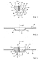
- the Fig. 1 shows a functional element 10 with a one-piece body part 12, which has no annular flange, but a cone-shaped surface 16, which merges without annular flange in a circular cylindrical part 14 whose diameter corresponds at least substantially to the maximum diameter of the conical surface 16. It can give in the region of the boundary between the conical surface 16 and the circular cylindrical portion 14 and at the transition from the circular cylindrical portion 14 and the free end face 39 cold-technical related rounded transitions.
- the functional element 10 shown has a neck part 18, which merges into a rivet section 20. The boundary between the neck portion 18 and the rivet portion 20 is 22.
- the body 16 of the functional element 10 also has a concentric with the longitudinal axis 24 arranged bore 26 with a threaded cylinder 28.
- the conical surface 16 extends concretely between the boundary to the circular cylindrical portion 14 of the functional element up to the boundary 36 to the neck portion 18 and has a cone angle ⁇ of 90 ° in this example.
- the circular cylindrical part in principle may have any length in the axial direction 24, wherein the circular cylindrical part can also be completely absent, so that the end face 39 of the functional element is at the location of the maximum diameter of the conical surface 16, ie at 34 in Fig. 1 and 3 ,
- the circular cylindrical portion 14 may have a diameter that is significantly smaller than the maximum diameter of the cone-shaped surface 16, so that a step at the border 34 in FIG Fig. 1 and 3 is present. Also, the part 14 could be formed as a part tapering away from the boundary 34 in the direction of the cone-shaped surface 16.
- the circular cylindrical part could, if desired, have a different peripheral shape.
- he could have a polygonal or grooved shape in plan view or be conically diverging or tapered or stepped.
- the included cone angle must be smaller than that of the cone-shaped area and, no matter which shape it has, no extended area may be supported on the sheet metal part and serve as a flange part. It should be buried at most a few corners in the sheet metal part and serve as anti-rotation, with such a construction is rather undesirable.
- anti-rotation features 38 which here have the form of lugs, which extend in each case in axial planes of the element.
- anti-rotation lugs 38 There are eight such anti-rotation lugs 38 are provided, but it could also be more or less.
- the anti-rotation lugs could also have the form of depressions or anti-rotation lugs and anti-rotation depressions may be provided, for example, alternately around the conical surface.
- the Fig. 2 shows a sheet metal part 40, which for receiving the functional element 10 of Fig. 1 is prepared.
- the sheet metal part 40 has a cone-shaped depression 42 with a hole 44 in the bottom region of the conical depression.
- the cone angle of the cone-shaped region 42 of the sheet metal part 40 preferably corresponds to the cone angle ⁇ of the conical surface 16 of the functional element 10.
- the hole 44 has a diameter which corresponds to the diameter of the neck portion 18 of the functional element 10 of Fig. 1
- the hole 44 may also have a slightly larger diameter, for example in the range of 0.2 mm larger, to allow easy insertion of the functional element into the hole.
- the hole 44 slightly smaller than the diameter of the neck part 18, whereby this is easily widened by insertion of the neck part 18 through the hole 44.
- the conical shape of the recess 42 facilitates in any case the orientation of the functional element 10 with the sheet metal part upon insertion of the functional element.
- the axis 46 of the hole 44 escapes with the longitudinal axis 24 of the functional element 10th
- the sheet metal preparation is usually carried out in a punch press or in a station of a progressive tool.
- the functional element 10 is then introduced using a setting head in the sheet metal part 40 and attached thereto, wherein the resulting assembly component in Fig. 3 is shown and explained in more detail below. It should be briefly expressed that the attachment of functional elements to sheet metal parts in presses and progressive dies or using robots or special frame devices is well known and will not be explained in detail here.
- annular bead 50 is formed from the rivet portion 20 of the functional element by displacement of material of the rivet portion in the direction of the annular flange 14.
- This annular bead 50 together with the neck portion 18, which is only slightly deformed during the displacement of the material of the rivet portion to form the annular bead 50, a clamping receptacle for the edge portion 48 of the hole 44 of the sheet metal part 40 and provides a corresponding Anpresswiderstand opposite to the arrow 47 in Fig. 3 ,
- the conical region of the sheet metal part 40 adjacent to the conical surface 16 provides for a corresponding contact resistance.
- the front side 39 of the functional element 10 is pressed from above in the direction of the arrow 47. Since a relatively large amount of material is present in the body part 12 of the functional element between the end face 39 and the rivet section, this area of the functional element is not deformed, so that a deformation of the threaded cylinder 28 is not to be feared.
- the cylindrical continuation 30 of the rivet section is not deformed during the attachment of the functional element, but merely guided into a bore of the die (not shown).
- annular hold-down can be applied to the setting head, which is arranged around the cylindrical part 14 and presses the sheet metal part adjacent to the conical recess 48 against a flat annular surface on the end face of the die used, said annular surface parallel to the sheet metal part 40 in the area around the cone-shaped recess 42 extends around.
- the assembly part according to Fig. 3 has the advantage, among other things, that a further component is attached on one side or the other can.
- a component on the front side 39 are fixed, in this case by means of a bolt, coming from above in Fig. 3 is screwed into the threaded cylinder 28.
- the attachment of the functional element on the sheet metal part is so strong or stiff that the attachment of a component to this end face 39 is readily permitted.
- the height of the circular cylindrical part 14, ie the axial thickness of this part can be selected to ensure a distance function between the further component and the sheet metal part 40.
- the end face 39 can be flush with the upper side of the sheet metal part 40 or higher or lower than this.
- the bolt would be inserted from below into the threaded cylinder 28.
- the component could be supported on the underside of the sheet metal part with respect to the cone-shaped part 16 of the functional element 10 or on the underside of the annular bead 50 or, with suitable dimensioning of the cylindrical continuation 30 on the free end side of this continuation.
- the cylindrical continuation 30 could serve as a bearing surface for a rotatable member, which is also secured with a bolt which is inserted from below into the threaded cylinder 28.
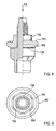
- Fig. 4 to 10 show a further example of a functional element according to the invention here in the form of a bolt element.
- the bolt member 110 has a head portion or body portion 112 which at least substantially the body portion 12 of the nut member of Fig. 1 corresponds and the bolt member also has a shaft portion 113 which extends from the top 139 of the circular cylindrical portion 114 away.
- the shaft portion 113 carries a threaded cylinder 128 and terminates in an insertion pin 129, for example according to EN ISO 4753.
- the circular-cylindrical part 114 via an annular transition 134, merges into a cone-shaped abutment surface 116, which merges directly into a rivet section 120, here provided with punching and riveting features at its lower end 121, which are in principle identical to the punching and riveting features of a conventional SBF bolt, but preferably has the shape that in the DE patent application 101470076.2 , That is, one can according to the bolt element Fig. 4 to 7 imagine that now no neck part is provided, which in principle in the formation of the functional element according to Fig. 1 to 3 is possible.
- the upper portion 118 of the punching and riveting portion 120 is at least substantially not deformed here, as shown Fig. 7 shows, so that this area could possibly be referred to as a neck part.
- anti-rotation features 138 are provided, which here have the form of lugs. It would also be possible, the anti-rotation lugs 138 according to Fig. 4 to 10 to replace with anti-rotation recesses, which could have the same shape as the lugs shown, but instead represent as elevations as recesses in the conical surface 116.
- the functional element is intended as a ground bolt, wherein one or more lugs or forks of current-conducting cables between the lower end face 160 of the nut 162 in Fig. 10 and the end face 139 are clamped (not shown).
- the outer diameter of the end face 160 of the nut member 162 is formed slightly larger than that of the end face 139 of the bolt member. This ensures that no lacquer or other protective coating can contaminate the end face 139, so that when attaching a cable lug this always fits snugly against the surface 139 and here takes place a high-quality electrical transition. If the diameter of the end face 160 were smaller than the diameter of the end face 139, there would be the risk that a lacquer deposit on the outer circumference of the end face 139 could prevent the cable lug from being fully seated against this end face.
- the nut member may be stamped at locations such as 166 so that the nut member 162 is not lost during transport of the unit consisting of the bolt and nut members 110, 162.
- the pitch of the thread of the nut member may be slightly different than the pitch of the thread of the pin member. But it is also enough to tighten the nut member firmly when the surfaces 160 and 139 fit snugly against each other.
- the nut member is loosened or unscrewed if necessary to clamp a cable lug or a plurality of lugs or a flange of a conductive housing or the like between the end face 160 of the nut member 162 and the end face 139 and the required conductive transition to the bolt member 110 and from the sheet metal part 140 to create.
- a shaping projection with a special profile to prevent twisting of a shape adapted opening having cable lug relative to the bolt member.
- the end face 139 of the head portion 112 a significant distance from the top of the sheet metal part, ie to the side of the sheet metal part, which is facing away from the Nietbördel 150, this is not mandatory for other bolt elements.
- the end face 139 may be set back significantly relative to the upper side of the sheet metal part, that is to say clearly below the sheet metal upper side, if appropriate by more than the sheet thickness, although this is normally undesirable.
- the desired state would be that the end face 139 is aligned with the top of the sheet metal part 140 around the cone-shaped recess, since this state favors the screwing of another component.
- the rivet section 120 is flanged after punching of the sheet metal part 140 by means of a corresponding forming surface of the die used so that it assumes the rounded shape 150, which in Fig. 10 is shown. In this case, the sheet metal part is deformed, as well as from Fig. 10 is apparent.
- the sheet material 148 from the edge region of the punched opening is received here by clamping in the crimped rivet section 120.
- a compressive stress in the cone-shaped area 142 is produced when a further component, which abuts flush against the end face 139 and the surrounding sheet metal die, is screwed on formed between the upper side of the sheet metal part and the clamping recess for the edge region 148 of the punching hole formed by the rivet section 120, if appropriate together with the "neck part" 118.
- the rounded ends 138 'of the anti-rotation lugs 138 ensure that the sheet metal part is not inadmissibly torn during punching, so that fatigue cracks in the sheet metal part at the points of anti-rotation lugs or at the locations of the radial projections 150' are to be feared.
- the bolt member 110 of Fig. 4 to 10 self-piercing introduced, the element can also be used in a pre-punched component, if desired.
- An advantage of the functional element according to the invention is that a wide range of sheet metal thicknesses can be covered with an element, so that, for example, the functional element according to the FIGS. 1 to 10 with sheet metal parts with thicknesses in the range of 0.6 mm to 3 mm or even up to 4 mm can be used, these thickness specifications are not to be understood as limiting and not on the statements according to Fig. 1 to 10 are limited.
- the functional elements described here can be made from any materials that achieve strength class 5.6 or higher.
- Such metal materials are usually carbon steels with 0.15 to 0.55% carbon content.
- the material of the functional elements all materials can be mentioned, which reach the strength values of Class 8 according to Isostandard in the context of cold working, for example, a 35B2 alloy according to DIN 1654.
- the fasteners thus formed are u.a.
- aluminum alloys, especially those with high strength, can be used for the functional elements, e.g. AlMg5.
- functional elements of higher strength magnesium alloys such as. AM50 come into question.
Landscapes
- Engineering & Computer Science (AREA)
- General Engineering & Computer Science (AREA)
- Mechanical Engineering (AREA)
- Connection Of Plates (AREA)
- Insertion Pins And Rivets (AREA)
Claims (31)
- Elément fonctionnel (10 ; 110) pour le montage sur une pièce en tôle, tel que par exemple élément formant écrou (10) ou élément formant boulon (110) comprenant une partie de corps (12 ; 112) ou une partie de tête qui, si nécessaire, présente à sa première extrémité axiale une partie cylindrique circulaire (14 ; 114) et qui se transforme, à son autre extrémité axiale, en une portion cylindrique formant rivet (20 ; 120),
caractérisé en ce que
dans la zone entre la première extrémité axiale ou une partie cylindrique circulaire qui y est prévue éventuellement et la portion formant rivet (20 ; 120), la partie de corps (12 ; 112) est pourvue d'une zone (16 ; 116) au moins sensiblement conique qui constitue une surface d'appui pour une zone conique correspondante (42 ; 142) d'une pièce en tôle (40 ; 140), et en ce que la partie cylindrique circulaire, si présente, possède à la limite (34 ; 134) vers la zone conique, un diamètre qui n'est pas supérieur au diamètre maximal de la zone conique et qui ne constitue donc ici pas une bride annulaire. - Elément fonctionnel selon la revendication 1,
caractérisé en ce que
il est prévu des caractéristiques de blocage antirotation (38 ; 138) dans la zone de la surface conique (16 ; 116). - Elément fonctionnel selon l'une des revendications précédentes,
caractérisé en ce que
la longueur axiale de la surface conique (16 ; 116) de la zone conique est au moins approximativement le double de l'épaisseur de tôle et est de préférence approximativement quatre fois l'épaisseur de tôle. - Elément fonctionnel selon l'une des revendications précédentes,
caractérisé en ce que
l'angle de cône enfermé (α) de la surface conique de la zone conique est dans la plage comprise entre 60° et 150°, de préférence dans la plage comprise entre 70° et 140° et en particulier entre 75° et 115° et il est de préférence particulière d'environ 90°. - Elément fonctionnel selon l'une des revendications précédentes,
caractérisé en ce que
la surface conique (16 ; 116) de la zone conique se transforme en la portion formant rivet (20 ; 120) via une partie de col cylindrique (18 ; 118). - Elément fonctionnel selon la revendication 5,
caractérisé en ce que
la partie de col (18 ; 118) présente une longueur axiale qui correspond au moins approximativement à l'épaisseur de tôle et est de préférence plus grande que celle-ci. - Elément fonctionnel selon l'une des revendications 2 à 6,
caractérisé en ce que
les caractéristiques de blocage antirotation (38 ; 138) présentent la forme de becs qui sont prévus sur la surface conique (16 ; 116). - Elément fonctionnel selon la revendication 7,
caractérisé en ce que
les becs de blocage antirotation (38 ; 138) s'étendent dans des plans axiaux. - Elément fonctionnel selon la revendication 7 ou 8,
caractérisé en ce que les becs de blocage antirotation (38 ; 138) sur la surface conique s'étendent au moins sensiblement sur la longueur axiale de la zone conique (16 ; 116). - Elément fonctionnel selon la revendication 7,
caractérisé en ce que
les caractéristiques de blocage antirotation présentent la forme de renfoncements prévus dans la surface conique. - Elément fonctionnel selon la revendication 10,
caractérisé en ce que
les renfoncements constituant les caractéristiques de blocage antirotation sont ménagés dans des plans axiaux de l'élément fonctionnel. - Elément fonctionnel selon l'une des revendications précédentes,
caractérisé en ce que
à sa première extrémité axiale, c'est-à-dire à l'extrémité de la partie de corps détournée de la portion formant rivet, la face frontale de la partie de corps ou la face frontale (39 ; 139) d'une partie cylindrique circulaire (14 ; 114) qui y est prévue éventuellement constitue une surface d'appui pour un composant qui doit être fixé sur la pièce en tôle (40 ; 140) au moyen de l'élément fonctionnel. - Elément fonctionnel selon la revendication 12,
caractérisé en ce que
l'épaisseur axiale de la partie cylindrique circulaire (14) est choisie pour réaliser une fonction d'écartement entre la pièce en tôle (40) et un composant monté sur la pièce en tôle au moyen de l'élément fonctionnel (10). - Elément fonctionnel selon l'une des revendications précédentes,
caractérisé en ce que
il s'agit d'un élément formant écrou (10) dans lequel la partie de corps (12) est pourvu d'un perçage central (26). - Elément fonctionnel selon l'une des revendications précédentes 1 à 13,
caractérisé en ce que
il s'agit d'un élément formant boulon (110) muni d'une partie de tige (113) qui est agencée sur le côté de la partie de corps (112) ou de la partie cylindrique circulaire (114), qui est détourné de la portion formant rivet (120). - Elément fonctionnel selon l'une des revendications précédentes,
caractérisé en ce que
il est prévu plusieurs becs de blocage antirotation sur la zone conique de l'élément fonctionnel qui s'étendent de préférence sur toute la longueur de la zone conique dans le plan axial et de préférence de façon régulière autour de l'axe longitudinal de l'élément fonctionnel. - Composant d'assemblage constitué par un élément fonctionnel, tel qu'un élément formant écrou (10) ou un élément formant boulon (110) selon l'une des revendications 1 à 16 et par une pièce en tôle (40),
caractérisé en ce que
une zone conique (42 ; 142) de la pièce en tôle est serrée dans un bourrelet annulaire (50 ; 150) constitué par la portion formant rivet, et en ce que la zone conique (42 ; 142) de la pièce en tôle s'appuie au moins sensiblement par toute la surface contre la zone conique de l'élément fonctionnel. - Composant d'assemblage selon la revendication 17,
caractérisé en ce que
il est prévu des caractéristiques de blocage antirotation (38 ; 138) dans la zone de la surface conique de l'élément fonctionnel, et en ce que le matériau de tôle de la pièce en tôle (40 ; 140) dans la zone conique (42 ; 142) est en engagement par coopération de formes avec les caractéristiques de blocage antirotation. - Composant d'assemblage selon la revendication 17 ou 18,
caractérisé en ce que
la longueur axiale de la surface conique (16 ; 116) correspond au moins approximativement au double de l'épaisseur de tôle et est de préférence approximativement quatre fois l'épaisseur de tôle. - Composant d'assemblage selon l'une des revendications précédentes 17 à 19,
caractérisé en ce que
l'angle de cône enfermé (α) de la surface conique (16 ; 116) est dans la plage comprise entre 60° et 150°, de préférence dans la plage comprise entre 70° et 140° et en particulier entre 75° et 115° et il est de préférence particulière d'environ 90°. - Composant d'assemblage selon l'une des revendications précédentes 17 à 20,
caractérisé en ce que
la surface conique (16 ; 116) se transforme en la portion formant rivet (20 ; 120) via une partie de col au moins sensiblement cylindrique (18 ; 118). - Composant d'assemblage selon la revendication 21,
caractérisé en ce que
la partie de col (18 ; 118) présente une longueur axiale qui correspond au moins approximativement à l'épaisseur de tôle et est de préférence plus grande que celle-ci. - Composant d'assemblage selon l'une des revendications précédentes 17 à 22,
caractérisé en ce que
il s'agit d'un élément formant écrou (10) dans lequel la partie de corps (12) est pourvu d'un perçage central (26). - Composant d'assemblage selon l'une des revendications 17 à 23,
caractérisé en ce que
le bourrelet annulaire (50) est formé par déplacement du matériau de la portion formant rivet (20). - Composant d'assemblage selon l'une des caractéristiques 17 à 23,
caractérisé en ce que
la portion formant rivet (120) est rabattue autour du bord (148) de l'ouverture (144) de la zone conique (142) de la pièce en tôle (140) pour former le bourrelet annulaire ou un rabattement de rivetage. - Composant d'assemblage selon l'une des revendications 17 à 22 ou 24 ou 25,
caractérisé en ce que
l'élément fonctionnel est un élément formant boulon qui présente une partie de tige (113) munie d'un filetage qui fait saillie de l'extrémité, détournée du rabattement de rivetage, de la zone conique de la partie de corps (112) ou d'une partie cylindrique circulaire (14) qui y est éventuellement prévue ou d'une extrémité, détournée du rabattement de rivetage, de la zone conique de la partie de corps (112) ou de l'extrémité frontale libre d'une partie cylindrique circulaire d'une saillie qui y est prévue. - Composant d'assemblage selon la revendication 26,
caractérisé en ce que
un élément formant écrou est vissé sur le filetage de la partie de tige et présente une bride s'étendant radialement qui, sur sa face frontale détournée du rabattement de rivetage, présente une surface d'attaque pour un outil de vissage, et autour de celle-ci une surface annulaire pour un poinçon d'une tête de pose, et qui, sur sa face frontale (160) tournée vers l'extrémité frontale (139) de l'élément formant boulon ou vers la face frontale libre d'une partie cylindrique circulaire (114) qui y est prévue, prend appui contre la face frontale (139) et est dimensionnée de préférence avec un diamètre supérieur à celui de cette face frontale (139), c'est-à-dire qu'elle chevauche celle-ci. - Composant d'assemblage selon la revendication 26 ou 27,
caractérisé en ce que
la saillie présente une forme périphérique qui sert de saillie de blocage antirotation pour une cosse de câble. - Composant d'assemblage selon l'une des revendications 26 à 28,
caractérisé en ce que
une cosse de câble se trouve entre l'élément formant écrou (162) et l'élément formant boulon. - Composant d'assemblage selon l'une des revendications 26 à 28,
caractérisé en ce que
il est pourvu d'un revêtement protecteur, mais non pas dans des zones de l'élément formant écrou et de l'élément formant boulon qui se touchent mutuellement. - Composant d'assemblage selon l'une des revendications 17 à 30,
caractérisé en ce que
la zone conique (16 ; 116) de l'élément fonctionnel (10 ; 110) s'étend au moins sensiblement sur toute la zone de tôle (42 ; 142) qui, après le rivetage de l'élément fonctionnel avec la pièce en tôle, se trouve en contact avec l'élément fonctionnel.
Priority Applications (1)
| Application Number | Priority Date | Filing Date | Title |
|---|---|---|---|
| EP03727326A EP1497073B1 (fr) | 2002-04-19 | 2003-04-17 | Element fonctionnel destine a etre fixe sur une piece en tole, composant d'assemblage produit a partir de cet element fonctionnel et procede de fixation d'un element fonctionnel a une piece en tole |
Applications Claiming Priority (6)
| Application Number | Priority Date | Filing Date | Title |
|---|---|---|---|
| PCT/EP2002/004365 WO2002086337A1 (fr) | 2001-04-20 | 2002-04-19 | Element fonctionnel destine a etre fixe sur une piece en tole, structure ainsi fabriquee et procede de fixation dudit element fonctionnel sur une piece en tole |
| WOPCT/EP02/04365 | 2002-04-19 | ||
| DE10249030 | 2002-10-21 | ||
| DE10249030A DE10249030A1 (de) | 2002-04-19 | 2002-10-21 | Funktionselement zur Anbringung an ein Blechteil, aus diesen hergestelltes Zusammenbauteil sowie Verfahren zur Anbringung des Funktionselements an ein Blechteil |
| EP03727326A EP1497073B1 (fr) | 2002-04-19 | 2003-04-17 | Element fonctionnel destine a etre fixe sur une piece en tole, composant d'assemblage produit a partir de cet element fonctionnel et procede de fixation d'un element fonctionnel a une piece en tole |
| PCT/EP2003/004075 WO2003089187A1 (fr) | 2002-04-19 | 2003-04-17 | Element fonctionnel destine a etre fixe sur une piece en tole, composant d'assemblage produit a partir de cet element fonctionnel et procede de fixation d'un element fonctionnel a une piece en tole |
Publications (2)
| Publication Number | Publication Date |
|---|---|
| EP1497073A1 EP1497073A1 (fr) | 2005-01-19 |
| EP1497073B1 true EP1497073B1 (fr) | 2008-10-01 |
Family
ID=99636248
Family Applications (1)
| Application Number | Title | Priority Date | Filing Date |
|---|---|---|---|
| EP03727326A Expired - Lifetime EP1497073B1 (fr) | 2002-04-19 | 2003-04-17 | Element fonctionnel destine a etre fixe sur une piece en tole, composant d'assemblage produit a partir de cet element fonctionnel et procede de fixation d'un element fonctionnel a une piece en tole |
Country Status (7)
| Country | Link |
|---|---|
| US (1) | US7357614B2 (fr) |
| EP (1) | EP1497073B1 (fr) |
| AU (1) | AU2003233992A1 (fr) |
| BR (1) | BR0309205B1 (fr) |
| DE (2) | DE10249030A1 (fr) |
| ES (1) | ES2312777T3 (fr) |
| WO (1) | WO2003089187A1 (fr) |
Cited By (3)
| Publication number | Priority date | Publication date | Assignee | Title |
|---|---|---|---|---|
| EP1985408A3 (fr) * | 2001-04-20 | 2011-11-16 | Profil Verbindungstechnik GmbH & Co. KG | Elément fonctionnel destiné à l'application sur un élément en tôle, composant fabriqué à partir de celui-ci et procédé d'application de l'élément fonctionnel sur un élément en tôle |
| DE102013217640A1 (de) | 2013-09-04 | 2015-03-05 | Profil Verbindungstechnik Gmbh & Co. Kg | Verfahren zur Anbringung eines Befestigungselements an ein Werkstück, Kombination einer Scheibe mit einer Matrize sowie Matrize |
| DE102020128341A1 (de) | 2020-10-28 | 2022-04-28 | Profil Verbindungstechnik Gmbh & Co. Kg | Elektrisches Anschlusselement zur formschlüssigen oder schweißtechnischen Anbringung an ein Blechteil |
Families Citing this family (18)
| Publication number | Priority date | Publication date | Assignee | Title |
|---|---|---|---|---|
| DE10243759B4 (de) * | 2002-09-20 | 2011-08-11 | PROFIL Verbindungstechnik GmbH & Co. KG, 61381 | Verfahren zur Erzeugung einer elektrisch leitenden Verbindung zwischen einer elektrischen Anschlusseinrichtung wie ein Kabelschuh und einem Blechteil, Befestigungselement und Zusammenbauteil |
| US20050047100A1 (en) * | 2003-09-02 | 2005-03-03 | Doo-Young Kim | Plasma display device and standoff of chassis base therefor |
| GB0406390D0 (en) | 2004-03-22 | 2004-04-21 | Bas Components Ltd | Vehicle roofrack mounting |
| GB0413866D0 (en) * | 2004-06-21 | 2004-07-21 | Bas Components Ltd | Captive fastener |
| DE102004062391A1 (de) | 2004-12-23 | 2006-07-13 | Profil-Verbindungstechnik Gmbh & Co. Kg | Ein durch Nieten an ein Blechteil anbringbares Element sowie Zusammenbauteil und Verfahren zur Erzeugung des Zusammenbauteils |
| DE102006003667A1 (de) * | 2006-01-26 | 2007-08-09 | Bayerische Motoren Werke Ag | Karosserie eines Fahrzeuges |
| DE102008059343B4 (de) * | 2008-09-23 | 2010-09-02 | Kerb-Konus-Vertriebs-Gmbh | Nietteil in einer Bauteilausnehmung |
| DE202008017562U1 (de) * | 2008-11-18 | 2010-02-11 | Kerb-Konus-Vertriebs-Gmbh | Nietteil mit geschlitztem Schaft |
| DE102008054807A1 (de) * | 2008-12-17 | 2010-06-24 | Hilti Aktiengesellschaft | Ankerschiene |
| DE102008054799A1 (de) * | 2008-12-17 | 2010-06-24 | Hilti Aktiengesellschaft | Ankerschiene |
| CN102135127A (zh) * | 2011-03-28 | 2011-07-27 | 江铃汽车股份有限公司 | 一种螺栓螺母组件以及一种用于狭小空间的紧固连接方法 |
| DE102012003819A1 (de) * | 2012-02-27 | 2013-08-29 | Profil Verbindungstechnik Gmbh & Co. Kg | Funktionselement zur fluiddichten Anbringung an ein Blechteil, Zusammenbauteil und Verfahren |
| DE102013204958A1 (de) * | 2012-03-27 | 2013-10-02 | Profil Verbindungstechnik Gmbh & Co. Kg | Funktionselement in Form eines Einpresselements |
| DE102013217633A1 (de) | 2013-09-04 | 2015-03-05 | Profil Verbindungstechnik Gmbh & Co. Kg | Stanzniet und Verfahren zur Befestigung einzelner Bauteile aneinander, von denen mindestens ein Bauteil durch ein Werkstück aus Verbundmaterial gebildet ist |
| DE102013217632A1 (de) | 2013-09-04 | 2015-03-05 | Profil Verbindungstechnik Gmbh & Co. Kg | Stanzniet sowie Verfahren und Vorrichtungen zur Befestigung einzelner Bauteile aneinander, von denen mindestens ein Bauteil durch ein Werkstück aus Verbundmaterial gebildet ist |
| DE102016119053A1 (de) * | 2016-10-07 | 2018-04-12 | Gustav Klauke Gmbh | Verfahren zur Herstellung einer mit einem Kabelschuh drehverbundenen Mutter und mit einem Kabelschuh drehverbundene Mutter |
| DE102019113560A1 (de) | 2018-05-30 | 2019-12-05 | Profil Verbindungstechnik Gmbh & Co. Kg | Selbststanzendes Nietelement, Zusammenbauteil bestehend aus dem Nietelement und einem Bauteil, Verfahren zur Herstellung des Zusammenbauteils und Matrize |
| DE102020111696A1 (de) * | 2020-04-29 | 2021-11-04 | Profil Verbindungstechnik Gmbh & Co. Kg | Funktionselement |
Family Cites Families (26)
| Publication number | Priority date | Publication date | Assignee | Title |
|---|---|---|---|---|
| NL111314C (fr) * | 1958-06-24 | |||
| US3117611A (en) * | 1961-04-03 | 1964-01-14 | Richard R Matthews | Clinch nut having adjacent frustoconical surfaces adapted to be secured in a sheet metal member |
| US3276499A (en) * | 1963-12-30 | 1966-10-04 | Republic Steel Corp | Flush-driven self-piercing and clinching nut and method of securing to a member |
| US3255797A (en) * | 1964-06-15 | 1966-06-14 | Warren R Attwood | Structural assemblies |
| DE3003908C2 (de) * | 1980-02-02 | 1984-10-18 | Profil-Verbindungstechnik Gmbh & Co Kg, 6382 Friedrichsdorf | Stehbolzen mit Stanz- und Nietverhalten |
| US4555838A (en) | 1983-03-28 | 1985-12-03 | Multifastener Corp. | Method of installing self-attaching fasteners |
| US5309618A (en) * | 1980-02-02 | 1994-05-10 | Profil Verbindungstechnik Gmbh & Co., Kg | Method of attaching a female fastener assembly to a panel |
| US5564873A (en) * | 1980-02-02 | 1996-10-15 | Multifastener Corporation | Self-attaching fastening element and method of attachment |
| US5207588A (en) | 1980-02-02 | 1993-05-04 | Multifastener Corporation | Electrical grounding stud |
| US4802803A (en) * | 1980-02-02 | 1989-02-07 | Multifastener Corporation | Fastening element and panel assembly |
| US4831698A (en) | 1983-03-28 | 1989-05-23 | Multifastener Corporation | Method of attaching a female element to a panel |
| US5722139A (en) * | 1981-01-28 | 1998-03-03 | Multifastener Corporation | Installation apparatus for attaching a fastener to a panel |
| US5441417A (en) * | 1981-01-28 | 1995-08-15 | Multifastener Corporation | Electrical grounding stud |
| FR2587421B1 (fr) * | 1985-09-18 | 1987-11-20 | Garonne Ets Auriol & Cie | Rivet semi-tubulaire |
| DE3546107A1 (de) * | 1985-12-24 | 1987-06-25 | Halfeneisen Gmbh & Co Kg | Ankerschiene fuer bautechnik |
| US5006025A (en) * | 1989-12-13 | 1991-04-09 | Avibank Mfg., Inc. | Self-locking nut |
| US5528812A (en) | 1991-10-31 | 1996-06-25 | Profil-Verbindungstechnik Gmbh & Co. Kg | Method of attaching a fastener to a plurality of panels |
| US5365654A (en) * | 1993-05-10 | 1994-11-22 | Thermalloy, Inc. | Interlocking attachment assembly |
| US5489176A (en) * | 1993-08-23 | 1996-02-06 | Emhart Inc. | Male clinch fastener with cold-formed locking flange and associated installation method |
| US5445483A (en) * | 1993-08-23 | 1995-08-29 | Emhart Inc. | Female clinch fastener with cold-formed locking flange and associated installation method |
| BE1008919A3 (fr) | 1994-11-25 | 1996-10-01 | Solvay | Copolymeres greffes du chlorure de vinyle presentant une resistance aux chocs elevee, procede pour les produire et utilisation de ces copolymeres pour l'extrusion de profiles. |
| EP1064466B1 (fr) * | 1999-01-26 | 2002-03-20 | Richard Bergner Verbindungstechnik GmbH & Co KG | Rivet a estamper |
| DE19909821A1 (de) * | 1999-03-05 | 2000-09-07 | Boellhoff Gmbh | Niet zum Fügen von Werkstücken |
| US20020098056A1 (en) * | 2001-01-22 | 2002-07-25 | Progressive Stamping Company, Inc. | Method of attaching a plate to a rod and assembly |
| DE10119505A1 (de) | 2001-04-20 | 2002-10-24 | Profil Verbindungstechnik Gmbh | Funktionselement zur Anbringung an ein Blechteil, aus diesen hergestelltes Zusammenbauteil sowie Verfahren zur Anbringung des Funktionselements an ein Bauteil |
| DE10147076A1 (de) * | 2001-09-25 | 2003-04-17 | Profil Verbindungstechnik Gmbh | Befestigungselement |
-
2002
- 2002-10-21 DE DE10249030A patent/DE10249030A1/de not_active Withdrawn
-
2003
- 2003-04-17 EP EP03727326A patent/EP1497073B1/fr not_active Expired - Lifetime
- 2003-04-17 BR BRPI0309205-4A patent/BR0309205B1/pt not_active IP Right Cessation
- 2003-04-17 AU AU2003233992A patent/AU2003233992A1/en not_active Abandoned
- 2003-04-17 ES ES03727326T patent/ES2312777T3/es not_active Expired - Lifetime
- 2003-04-17 DE DE50310573T patent/DE50310573D1/de not_active Expired - Lifetime
- 2003-04-17 US US10/510,375 patent/US7357614B2/en not_active Expired - Lifetime
- 2003-04-17 WO PCT/EP2003/004075 patent/WO2003089187A1/fr not_active Ceased
Cited By (8)
| Publication number | Priority date | Publication date | Assignee | Title |
|---|---|---|---|---|
| EP1985408A3 (fr) * | 2001-04-20 | 2011-11-16 | Profil Verbindungstechnik GmbH & Co. KG | Elément fonctionnel destiné à l'application sur un élément en tôle, composant fabriqué à partir de celui-ci et procédé d'application de l'élément fonctionnel sur un élément en tôle |
| US8261422B2 (en) | 2001-04-20 | 2012-09-11 | Profil Verbindungstechnik Gmbh & Co., Kg | Functional element for the attachment to a sheet metal part, component assembly manufactured from these and also a method for the attachment of the functional element to a sheet metal part |
| US8864429B2 (en) | 2001-04-20 | 2014-10-21 | Profil Verbindungstechnik Gmbh & Co. Kg | Functional element for the attachment to a sheet metal part, component assembly manufactured from these and also a method for the attachment of the functional element to a sheet metal part |
| DE102013217640A1 (de) | 2013-09-04 | 2015-03-05 | Profil Verbindungstechnik Gmbh & Co. Kg | Verfahren zur Anbringung eines Befestigungselements an ein Werkstück, Kombination einer Scheibe mit einer Matrize sowie Matrize |
| EP2845680A1 (fr) | 2013-09-04 | 2015-03-11 | Profil Verbindungstechnik GmbH & Co. KG | Procédé pour attacher un élément de fixation à une pièce, combinaison d'une rondelle avec matrice d'emboutissage et ladite matrice |
| DE102020128341A1 (de) | 2020-10-28 | 2022-04-28 | Profil Verbindungstechnik Gmbh & Co. Kg | Elektrisches Anschlusselement zur formschlüssigen oder schweißtechnischen Anbringung an ein Blechteil |
| EP3993169A1 (fr) | 2020-10-28 | 2022-05-04 | Profil Verbindungstechnik GmbH & Co. KG | Élément de connexion électrique destiné à l'application par liaison par complémentarité de forme ou par technique de soudage à une pièce en tôle |
| US12444862B2 (en) | 2020-10-28 | 2025-10-14 | Profil Verbindungstechnik Gmbh & Co. Kg | Electrical connection element for a form-fitted or welding attachment to a sheet metal part |
Also Published As
| Publication number | Publication date |
|---|---|
| BR0309205A (pt) | 2005-02-09 |
| WO2003089187A1 (fr) | 2003-10-30 |
| BR0309205B1 (pt) | 2013-05-28 |
| EP1497073A1 (fr) | 2005-01-19 |
| DE50310573D1 (de) | 2008-11-13 |
| US20050158142A1 (en) | 2005-07-21 |
| US7357614B2 (en) | 2008-04-15 |
| DE10249030A1 (de) | 2003-11-06 |
| AU2003233992A1 (en) | 2003-11-03 |
| ES2312777T3 (es) | 2009-03-01 |
Similar Documents
| Publication | Publication Date | Title |
|---|---|---|
| EP1381785B1 (fr) | Element fonctionnel destine a etre fixe sur une piece en tole, structure ainsi fabriquee et procede de fixation dudit element fonctionnel sur une piece en tole | |
| EP1674741B1 (fr) | Elément à montage par rivetage dans une pièce en tôle, procédé de montage et ensemble ainsi formé | |
| WO2003089187A1 (fr) | Element fonctionnel destine a etre fixe sur une piece en tole, composant d'assemblage produit a partir de cet element fonctionnel et procede de fixation d'un element fonctionnel a une piece en tole | |
| EP2292940B1 (fr) | Elément d'écrou auto-perforant et composant constitué de l'élément d'écrou et d'un élément de tôle | |
| DE60208103T2 (de) | Mit einer Zierkappe versehene Radmutter und Verfahren zum Zusammensetzen derselben | |
| DE4033763C2 (de) | Vorrichtung zum Sichern einer in einer Öffnung in einer Verkleidung aufgenommenen Mutter | |
| EP0667936B1 (fr) | Procede de fabrication un element composite etre resistant a l'ejection et de se contourner par presser un element d'insertion dans une piece en tole et element d'insertion convenable pour ce procede | |
| DE19902461B4 (de) | Mutter mit T-förmigem Querschnitt | |
| EP2980426B1 (fr) | Composant d'assemblage comprenant un element a sertir et une partie de tole | |
| EP2412991B1 (fr) | Elément d'écrou auto-perforant et composant constitué de l'élément d'écrou et d'un élément de tôle | |
| EP1430229B1 (fr) | Element de fixation | |
| EP1806509A2 (fr) | Élément fonctionnel, ensemble de montage composés de l'élément fonctionnel et d'une plaque ainsi que d'une procédure de attacher d'un élément fonctionnel | |
| EP2549128A1 (fr) | Elément fonctionnel avec propriétés de sécurisation contre la torsion et composant composé d'un élément fonctionnel et d'une partie en tôle | |
| DE10243759B4 (de) | Verfahren zur Erzeugung einer elektrisch leitenden Verbindung zwischen einer elektrischen Anschlusseinrichtung wie ein Kabelschuh und einem Blechteil, Befestigungselement und Zusammenbauteil | |
| EP1690013A1 (fr) | Element fonctionnel, composant d'assemblage compose de l'element fonctionnel combine a une tole, procede de fabrication du composant d'assemblage et procede de fabrication de l'element fonctionnel | |
| EP3309414B1 (fr) | Élément de fonction pour fixation étanche aux fluides sur une pièce de tôlerie, ensemble de montage et procédé | |
| WO2003002879A2 (fr) | Ecrou a river aveugle autoperforant | |
| DE102018117131A1 (de) | Selbststanzendes Element und Zusammenbauteil bestehend aus dem Element und einem Blechteil | |
| EP1003243B1 (fr) | Procédé de fabrication d'une connexion électrique à une partie en tôle et ensemble de montage | |
| EP0406801B1 (fr) | Dispositif de fixation | |
| DE102008016273B4 (de) | Verfahren zum Verbinden eines Funktionselementes mit einem Metallblech sowie Verbindung zwischen einem Metallblech und einem Funktionselement | |
| EP3575618B1 (fr) | Élément rivet autoperforant, composant d'assemblage composé de l'élément rivet et d'un composant, procédé de fabrication du composant d'assemblage et matrice | |
| EP3715648A1 (fr) | Système de serrage, utilisation d'un disque de serrage et procédé de précontrainte d'un élément de fixation | |
| DE9321296U1 (de) | Verbundteil aus einem Flachmaterial und einem darin eingepreßten Einpreßteil sowie dafür geeignete Einpreßteile | |
| EP1379790B1 (fr) | Procede de fabrication d'un element de construction comprenant une partie en tole et une tige filetee ainsi que l'element de construction. |
Legal Events
| Date | Code | Title | Description |
|---|---|---|---|
| PUAI | Public reference made under article 153(3) epc to a published international application that has entered the european phase |
Free format text: ORIGINAL CODE: 0009012 |
|
| 17P | Request for examination filed |
Effective date: 20041103 |
|
| AK | Designated contracting states |
Kind code of ref document: A1 Designated state(s): AT BE BG CH CY CZ DE DK EE ES FI FR GB GR HU IE IT LI LU MC NL PT RO SE SI SK TR |
|
| AX | Request for extension of the european patent |
Extension state: AL LT LV MK |
|
| RAP1 | Party data changed (applicant data changed or rights of an application transferred) |
Owner name: PROFIL VERBINDUNGSTECHNIK GMBH & CO. KG |
|
| GRAP | Despatch of communication of intention to grant a patent |
Free format text: ORIGINAL CODE: EPIDOSNIGR1 |
|
| GRAS | Grant fee paid |
Free format text: ORIGINAL CODE: EPIDOSNIGR3 |
|
| GRAA | (expected) grant |
Free format text: ORIGINAL CODE: 0009210 |
|
| AK | Designated contracting states |
Kind code of ref document: B1 Designated state(s): DE ES FR GB IT |
|
| REG | Reference to a national code |
Ref country code: GB Ref legal event code: FG4D Free format text: NOT ENGLISH |
|
| REF | Corresponds to: |
Ref document number: 50310573 Country of ref document: DE Date of ref document: 20081113 Kind code of ref document: P |
|
| REG | Reference to a national code |
Ref country code: ES Ref legal event code: FG2A Ref document number: 2312777 Country of ref document: ES Kind code of ref document: T3 |
|
| PLBE | No opposition filed within time limit |
Free format text: ORIGINAL CODE: 0009261 |
|
| STAA | Information on the status of an ep patent application or granted ep patent |
Free format text: STATUS: NO OPPOSITION FILED WITHIN TIME LIMIT |
|
| 26N | No opposition filed |
Effective date: 20090702 |
|
| REG | Reference to a national code |
Ref country code: FR Ref legal event code: PLFP Year of fee payment: 14 |
|
| REG | Reference to a national code |
Ref country code: FR Ref legal event code: PLFP Year of fee payment: 15 |
|
| REG | Reference to a national code |
Ref country code: FR Ref legal event code: PLFP Year of fee payment: 16 |
|
| PGFP | Annual fee paid to national office [announced via postgrant information from national office to epo] |
Ref country code: GB Payment date: 20220224 Year of fee payment: 20 |
|
| PGFP | Annual fee paid to national office [announced via postgrant information from national office to epo] |
Ref country code: IT Payment date: 20220310 Year of fee payment: 20 Ref country code: FR Payment date: 20220221 Year of fee payment: 20 |
|
| PGFP | Annual fee paid to national office [announced via postgrant information from national office to epo] |
Ref country code: ES Payment date: 20220505 Year of fee payment: 20 Ref country code: DE Payment date: 20220223 Year of fee payment: 20 |
|
| REG | Reference to a national code |
Ref country code: DE Ref legal event code: R071 Ref document number: 50310573 Country of ref document: DE |
|
| REG | Reference to a national code |
Ref country code: ES Ref legal event code: FD2A Effective date: 20230426 |
|
| REG | Reference to a national code |
Ref country code: GB Ref legal event code: PE20 Expiry date: 20230416 |
|
| PG25 | Lapsed in a contracting state [announced via postgrant information from national office to epo] |
Ref country code: ES Free format text: LAPSE BECAUSE OF EXPIRATION OF PROTECTION Effective date: 20230418 |
|
| PG25 | Lapsed in a contracting state [announced via postgrant information from national office to epo] |
Ref country code: GB Free format text: LAPSE BECAUSE OF EXPIRATION OF PROTECTION Effective date: 20230416 |