EP1497091B1 - Ensemble de coulee et utilisation d'une bande de focalisation isoelectrique - Google Patents
Ensemble de coulee et utilisation d'une bande de focalisation isoelectrique Download PDFInfo
- Publication number
- EP1497091B1 EP1497091B1 EP03744619A EP03744619A EP1497091B1 EP 1497091 B1 EP1497091 B1 EP 1497091B1 EP 03744619 A EP03744619 A EP 03744619A EP 03744619 A EP03744619 A EP 03744619A EP 1497091 B1 EP1497091 B1 EP 1497091B1
- Authority
- EP
- European Patent Office
- Prior art keywords
- gel
- enclosure
- mold
- section
- accordance
- Prior art date
- Legal status (The legal status is an assumption and is not a legal conclusion. Google has not performed a legal analysis and makes no representation as to the accuracy of the status listed.)
- Expired - Lifetime
Links
- 238000005266 casting Methods 0.000 title claims abstract description 27
- 238000001155 isoelectric focusing Methods 0.000 title claims abstract description 17
- 239000000499 gel Substances 0.000 claims abstract description 69
- 239000000463 material Substances 0.000 claims description 9
- 238000007373 indentation Methods 0.000 claims description 6
- 229920002401 polyacrylamide Polymers 0.000 claims description 5
- 239000000178 monomer Substances 0.000 claims description 4
- HRPVXLWXLXDGHG-UHFFFAOYSA-N Acrylamide Chemical compound NC(=O)C=C HRPVXLWXLXDGHG-UHFFFAOYSA-N 0.000 claims description 3
- 239000011543 agarose gel Substances 0.000 claims description 3
- 238000006116 polymerization reaction Methods 0.000 claims description 2
- 239000007787 solid Substances 0.000 claims description 2
- 239000011347 resin Substances 0.000 claims 2
- 229920005989 resin Polymers 0.000 claims 2
- 238000000926 separation method Methods 0.000 abstract description 16
- 238000001962 electrophoresis Methods 0.000 description 9
- 238000000034 method Methods 0.000 description 6
- 239000000203 mixture Substances 0.000 description 4
- 102000004169 proteins and genes Human genes 0.000 description 4
- 108090000623 proteins and genes Proteins 0.000 description 4
- 230000008901 benefit Effects 0.000 description 3
- 239000011159 matrix material Substances 0.000 description 3
- 229920000936 Agarose Polymers 0.000 description 2
- 238000007796 conventional method Methods 0.000 description 2
- 230000005684 electric field Effects 0.000 description 2
- 125000000524 functional group Chemical group 0.000 description 2
- 239000002480 mineral oil Substances 0.000 description 2
- 235000010446 mineral oil Nutrition 0.000 description 2
- 239000003921 oil Substances 0.000 description 2
- 229920003023 plastic Polymers 0.000 description 2
- 239000004033 plastic Substances 0.000 description 2
- 239000011343 solid material Substances 0.000 description 2
- 229920002307 Dextran Polymers 0.000 description 1
- NBIIXXVUZAFLBC-UHFFFAOYSA-N Phosphoric acid Chemical group OP(O)(O)=O NBIIXXVUZAFLBC-UHFFFAOYSA-N 0.000 description 1
- ABLZXFCXXLZCGV-UHFFFAOYSA-N Phosphorous acid Chemical group OP(O)=O ABLZXFCXXLZCGV-UHFFFAOYSA-N 0.000 description 1
- 239000004372 Polyvinyl alcohol Substances 0.000 description 1
- VYPSYNLAJGMNEJ-UHFFFAOYSA-N Silicium dioxide Chemical compound O=[Si]=O VYPSYNLAJGMNEJ-UHFFFAOYSA-N 0.000 description 1
- 229920002472 Starch Polymers 0.000 description 1
- 239000002253 acid Substances 0.000 description 1
- 150000007513 acids Chemical class 0.000 description 1
- 229920006397 acrylic thermoplastic Polymers 0.000 description 1
- 239000000853 adhesive Substances 0.000 description 1
- 230000001070 adhesive effect Effects 0.000 description 1
- 238000004458 analytical method Methods 0.000 description 1
- 125000005620 boronic acid group Chemical group 0.000 description 1
- 125000002843 carboxylic acid group Chemical group 0.000 description 1
- 239000001913 cellulose Substances 0.000 description 1
- 229920002678 cellulose Polymers 0.000 description 1
- 238000010276 construction Methods 0.000 description 1
- 239000003431 cross linking reagent Substances 0.000 description 1
- 238000009792 diffusion process Methods 0.000 description 1
- 238000011067 equilibration Methods 0.000 description 1
- 150000002148 esters Chemical group 0.000 description 1
- 230000002452 interceptive effect Effects 0.000 description 1
- 239000007788 liquid Substances 0.000 description 1
- 238000004519 manufacturing process Methods 0.000 description 1
- 239000012528 membrane Substances 0.000 description 1
- 230000005012 migration Effects 0.000 description 1
- 238000013508 migration Methods 0.000 description 1
- 238000000465 moulding Methods 0.000 description 1
- IJGRMHOSHXDMSA-UHFFFAOYSA-N nitrogen Substances N#N IJGRMHOSHXDMSA-UHFFFAOYSA-N 0.000 description 1
- 229910052757 nitrogen Inorganic materials 0.000 description 1
- QJGQUHMNIGDVPM-UHFFFAOYSA-N nitrogen group Chemical group [N] QJGQUHMNIGDVPM-UHFFFAOYSA-N 0.000 description 1
- 229920003229 poly(methyl methacrylate) Polymers 0.000 description 1
- 239000004417 polycarbonate Substances 0.000 description 1
- 229920000515 polycarbonate Polymers 0.000 description 1
- 229920002451 polyvinyl alcohol Polymers 0.000 description 1
- 235000019422 polyvinyl alcohol Nutrition 0.000 description 1
- 125000002924 primary amino group Chemical group [H]N([H])* 0.000 description 1
- 239000000741 silica gel Substances 0.000 description 1
- 229910002027 silica gel Inorganic materials 0.000 description 1
- 239000008107 starch Substances 0.000 description 1
- 235000019698 starch Nutrition 0.000 description 1
- 125000000542 sulfonic acid group Chemical group 0.000 description 1
- ISXSCDLOGDJUNJ-UHFFFAOYSA-N tert-butyl prop-2-enoate Chemical compound CC(C)(C)OC(=O)C=C ISXSCDLOGDJUNJ-UHFFFAOYSA-N 0.000 description 1
- XLYOFNOQVPJJNP-UHFFFAOYSA-N water Substances O XLYOFNOQVPJJNP-UHFFFAOYSA-N 0.000 description 1
- 238000009736 wetting Methods 0.000 description 1
Images

Classifications
-
- G—PHYSICS
- G01—MEASURING; TESTING
- G01N—INVESTIGATING OR ANALYSING MATERIALS BY DETERMINING THEIR CHEMICAL OR PHYSICAL PROPERTIES
- G01N27/00—Investigating or analysing materials by the use of electric, electrochemical, or magnetic means
- G01N27/26—Investigating or analysing materials by the use of electric, electrochemical, or magnetic means by investigating electrochemical variables; by using electrolysis or electrophoresis
- G01N27/416—Systems
- G01N27/447—Systems using electrophoresis
- G01N27/44756—Apparatus specially adapted therefor
- G01N27/44795—Isoelectric focusing
-
- B—PERFORMING OPERATIONS; TRANSPORTING
- B29—WORKING OF PLASTICS; WORKING OF SUBSTANCES IN A PLASTIC STATE IN GENERAL
- B29C—SHAPING OR JOINING OF PLASTICS; SHAPING OF MATERIAL IN A PLASTIC STATE, NOT OTHERWISE PROVIDED FOR; AFTER-TREATMENT OF THE SHAPED PRODUCTS, e.g. REPAIRING
- B29C39/00—Shaping by casting, i.e. introducing the moulding material into a mould or between confining surfaces without significant moulding pressure; Apparatus therefor
- B29C39/02—Shaping by casting, i.e. introducing the moulding material into a mould or between confining surfaces without significant moulding pressure; Apparatus therefor for making articles of definite length, i.e. discrete articles
- B29C39/10—Shaping by casting, i.e. introducing the moulding material into a mould or between confining surfaces without significant moulding pressure; Apparatus therefor for making articles of definite length, i.e. discrete articles incorporating preformed parts or layers, e.g. casting around inserts or for coating articles
-
- B—PERFORMING OPERATIONS; TRANSPORTING
- B29—WORKING OF PLASTICS; WORKING OF SUBSTANCES IN A PLASTIC STATE IN GENERAL
- B29C—SHAPING OR JOINING OF PLASTICS; SHAPING OF MATERIAL IN A PLASTIC STATE, NOT OTHERWISE PROVIDED FOR; AFTER-TREATMENT OF THE SHAPED PRODUCTS, e.g. REPAIRING
- B29C39/00—Shaping by casting, i.e. introducing the moulding material into a mould or between confining surfaces without significant moulding pressure; Apparatus therefor
- B29C39/22—Component parts, details or accessories; Auxiliary operations
- B29C39/26—Moulds or cores
-
- B—PERFORMING OPERATIONS; TRANSPORTING
- B29—WORKING OF PLASTICS; WORKING OF SUBSTANCES IN A PLASTIC STATE IN GENERAL
- B29C—SHAPING OR JOINING OF PLASTICS; SHAPING OF MATERIAL IN A PLASTIC STATE, NOT OTHERWISE PROVIDED FOR; AFTER-TREATMENT OF THE SHAPED PRODUCTS, e.g. REPAIRING
- B29C33/00—Moulds or cores; Details thereof or accessories therefor
- B29C33/12—Moulds or cores; Details thereof or accessories therefor with incorporated means for positioning inserts, e.g. labels
-
- B—PERFORMING OPERATIONS; TRANSPORTING
- B29—WORKING OF PLASTICS; WORKING OF SUBSTANCES IN A PLASTIC STATE IN GENERAL
- B29C—SHAPING OR JOINING OF PLASTICS; SHAPING OF MATERIAL IN A PLASTIC STATE, NOT OTHERWISE PROVIDED FOR; AFTER-TREATMENT OF THE SHAPED PRODUCTS, e.g. REPAIRING
- B29C33/00—Moulds or cores; Details thereof or accessories therefor
- B29C33/56—Coatings, e.g. enameled or galvanised; Releasing, lubricating or separating agents
- B29C33/68—Release sheets
-
- B—PERFORMING OPERATIONS; TRANSPORTING
- B29—WORKING OF PLASTICS; WORKING OF SUBSTANCES IN A PLASTIC STATE IN GENERAL
- B29K—INDEXING SCHEME ASSOCIATED WITH SUBCLASSES B29B, B29C OR B29D, RELATING TO MOULDING MATERIALS OR TO MATERIALS FOR MOULDS, REINFORCEMENTS, FILLERS OR PREFORMED PARTS, e.g. INSERTS
- B29K2105/00—Condition, form or state of moulded material or of the material to be shaped
- B29K2105/0058—Liquid or visquous
- B29K2105/0061—Gel or sol
Definitions
- This invention resides in the field of electrophoretic separation media, and addresses in particular the elongated gel strips used for isoelectric focusing.
- Electrophoresis for purifying proteins and separating complex protein mixtures has developed to the point where it is now performed in many different ways. Variations arise in the composition of the separation medium, the geometrical configuration of the separation medium, the manner in which mobility through the medium is achieved, and the parameter on which separation is based.
- Isoelectric focusing in which the proteins are separated in a linear manner according to their isoelectric points.
- Isoelectric focusing is at times used as the entire separation process, and at other times as the first dimension of a two-dimensional separation, the second dimension being performed by placing the linear medium with its isoelectrically focused zones along one edge of a two-dimensional ("slab"-shaped) separation medium.
- An electric field is then imposed on the two-dimensional medium in a direction transverse to the linear medium, causing migration of the contents of each focused zone out of that medium and into the two-dimensional medium along parallel paths where the contents of each zone are separated according to a parameter other than isoelectric point.
- the proteins in the original sample thus have the benefit of being separated according to two parameters.
- the pH gradient is commonly achieved by using a dimensionally stable medium that consists of a molecular matrix to which functional groups have been attached that are either charged or become charged when the medium is placed in an electric field.
- Strips of solid media that contain such groups are commonly referred to as "immobilized pH gradient" ("IPG") strips.
- IPG immobilized pH gradient
- the composition and structure of these strips are described by Rosengren et al. in United States Patent No. 4,130,470, issued December 19, 1978 .
- the solid material that forms the matrix of the strip is either a granular, fibrous, or membrane material, or a gel. Examples of suitable gels are polyacrylamide, cellulose, agarose, dextran, polyvinylalcohol, starch, and silica gel.
- the functional groups which are immobilized on the matrix by covalent bonding or other means, may be positively charged groups such as amino or other nitrogen-bearing groups or negatively-charged groups such as carboxylic acid groups, sulfonic acid groups, boronic acid groups, phosphonic or phosphoric acid groups, or esters of these acids.
- the typical fabrication procedure for polymeric media is to copolymerize charged or chargeable monomers with uncharged monomers or to include charged crosslinking agents. A monotonic increase or decrease in the concentration of the charged or chargeable groups will produce the desired gradient.
- the linear isoelectric focusing medium can be either a tube gel or a flat gel strip, and both have disadvantages.
- the tube gel must be removed from its tubular enclosure after the first-dimension separation so that the tube gel can be placed in direct contact with the slab gel for the second-dimension separation.
- Tube gels are difficult to remove from their enclosures, and once removed, are difficult to handle due to their lack of rigidity and the need to minimize contact of the gel with the user's fingers.
- Strip gels by contrast, are relatively easily to manipulate since they are not run inside enclosures and are cast over a plastic backing sheet which the user can handle without touching the gel. Nevertheless, strip gels are generally supplied in dehydrated form and must be rehydrated before use.
- the mineral oil must be removed completely since any residual oil may interfere with the electrical continuity between the strip and the slab gel. Removal of the oil can be a difficult and messy procedure.
- the equipment used to perform isoelectric focusing on a strip gel is relatively complicated and expensive owing to the configuration of the gel, the manner in which the gel is placed on the equipment, and the manner in which the electrical contacts are made.
- the present invention resides in an assembly in which an isoelectric focusing (IEF) gel can be cast and used, the assembly offering the benefits of both a tube gel and a flat IEF strip and none of the disadvantages.
- the assembly consists of a rod-shaped casting mold split longitudinally into two halves or half casting molds, each having a half-circle profile so that when the halves are combined along their flat contacting surfaces, the completed mold is tubular in shape with a circular cross section. Grooves or indentations are cut into each of the two contacting surfaces, the grooves in direct opposition to one another to form a chamber of rectangular cross section extending the full length of the mold and open at both ends.
- One groove receives a flexible backing strip for the gel and the interior of the other, when the two halves are combined, serves as the casting chamber for the gel.
- the gel once cast in this chamber with the backing strip in place will adhere to the backing strip which can be grasped to remove the gel from the mold.
- the circular cross section of the exterior of the combined halves of the assembly permits the assembly to be used in electrophoresis apparatus that is designed for a tube gel, i.e., laboratory instrumentation that is designed to receive a tube gel in its tubular enclosure and to provide the electrical connections to the tube gel that are necessary for electrophoresis to take place.
- the tube gel shape also permits the gel to be loaded with sample by the enhanced procedures that are used with tube gels, thereby permitting greater sample quantities to be loaded and sample loading to be accomplished in shorter periods of time.
- the split-mold construction then enables the user to open the assembly after isoelectric focusing is completed and to easily remove and reposition the gel without touching the gel.
- the circular cross section extends less than the full length of the assembly, occupying instead only a segment beginning at one end of the assembly, the remaining length being a rectangular cross section to facilitate the sue of screws, clamps, or other means to secure the two halves together in a readily removable manner.
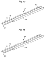
- FIGS. 1a and 1b are perspective views of the two half casting molds, respectively, of one example of an assembly in accordance with the present invention.
- FIGS. 2a and 2b are end views of the two half casting molds shown in FIGS. 1a and 1b , respectively.
- FIG. 3 is an end view of the two half casting molds of FIGS. 1a and 1b combined to form the completed assembly.
- FIG. 4a is a side view of the completed assembly shown in the preceding drawings.
- FIG. 4b is a side view of one of the two mold halves in the process of having the gel removed after electrophoresis has taken place.
- FIGS. 1a and 1b represent the upper half casting mold 11 and the lower half casting mold 12, respectively, each shown with their contacting surfaces 13, 14, turned upward.
- the contacting surfaces are both flat except for the shallow groove 15, 16 extending lengthwise along the center line of each surface.
- the grooves and the profiles of each of the half casting molds are more readily visible in the end views of FIGS. 2a and 2b , which show that both grooves have a flat or horizontal floor and an overall rectangular cross section, and the grooves are of unequal depths, the groove 15 in the upper half casting mold 11 being less deep than the groove 16 in the lower half casting mold 12.
- the shallow groove 15 receives the flexible strip of solid material that supports the gel, while the deep groove 16 serves as the gel casting chamber.
- the two grooves may be of equal width or may differ in width. In the latter case, the groove 15 for the support strip may be slightly wider than the groove 16 for the gel.
- FIG. 3 shows the two half molds combined to form a completed mold and gel enclosure ready for sample loading and isoelectric focusing.
- the flexible strip 17 (which is shown in FIG. 3 ) is first placed in the shallow groove 15 of the upper half mold 11, and the upper half mold is then turned face down to place the two flat surfaces in contact. The rest of the chamber formed by the two mated grooves is then filled with gel-forming solution and the gel is cast.
- the forward ends of the half molds each have semi-circular profiles 21, 22, as both the perspective views ( FIGS. 1a and 1b ) and the end views ( FIGS. 2a and 2b ) illustrate.
- the outer contour is that of a circular cross-section tube.
- This circular cross section enables the user to insert the assembly, with gel inside, in an electrophoresis apparatus designed for tube gels, such as the various PROTEAN® electrophoresis cells manufactured by Bio-Rad Laboratories, Inc., Hercules, California, USA.
- the remainders of the half molds have rectangular profiles 23, 24, and this portion of the assembled mold is therefore rectangular in cross section.
- the particular example shown in the drawings has a square cross section.
- the purpose of the change in cross section is to facilitate the securing of the two half molds together, since rectangular shaped halves are more easily secured together by screws, bolts, or clamps.
- the example shown in the drawings has six sets of screw holes 26.
- Alternative means of securing the two halves together in a readily releasable or openable fashion will be apparent to those skilled in the art. Examples are clamps, snap fittings, friction fittings, and non-permanent adhesives.
- the two halves as shown are fully separable, they may alternatively be joined by hinges, pivot connections, or strips of flexible material.
- Electrophoretic sample loading i.e., the loading of a sample by placing the sample at one end of the gel and imposing an electric current along the length of the gel to drive the sample into the gel, is particularly convenient and useful. Once the sample is loaded, isoelectric focusing can proceed by conventional techniques.
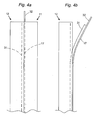
- FIGS. 4a and 4b Removal of the gel from the mold is illustrated in FIGS. 4a and 4b .
- the side view of FIG. 4a shows the assembled mold halves in an upright position.
- the gel 31 is shown by a dashed line in the lower mold half 12 which is on the left of the assembly in this view, and the flexible support strip 17 is shown by a dashed line in the upper mold half 11 on the right.
- One end 32 of the support strip protrudes from the end of the mold.
- the mold halves are separated as shown in FIG. 4b , leaving the lower mold half 12 with the gel 31 inside and the support strip 17 adhering to the gel.
- the user grasps the free end 32 of the support strip to pull the gel out of its groove.
- the materials used in the practice of this invention are not critical to the invention itself and can vary. Gels of any of the compositions noted above can be used, although polyacrylamide and agarose gels are the most common. Polyacrylamide gels are particularly preferred in view of their widespread use.
- the flexible support strip 17 can be any material that supports and adheres to the gel without interfering with the separation properties of the gel. Preferred support strips are those that couple with the gel material, such as agarose or acrylamide, during the gel polymerization process. A description of support materials of this type is found in Chanumson, S., et al., United States Patent No. 4,415,428 , "Support for Electrophoresis and Method of Producing Same," issued November 16, 1983.
- the dimensions of the molds are likewise noncritical to the invention and can vary. In most cases, it is contemplated that the grooves will have depths within the range of from about 0.01 cm to about 0.10 cm, and widths within the range of from about 0.1 cm to about 1.0 cm, and the circular cross section segment of the mold assembly will have a length of from about 2.0 cm to about 5.0 cm in length and a diameter of from about 0.5 cm to about 2.5 cm (which will also be the length of one side of the square cross section segment). The total length of the mold may range from about 10 cm to about 30 cm.
- the total length is 18 cm
- the length of the circular section is 3.8 cm
- the diameter of the circular section and the length of one side of the square section is 0.9 cm
- the shallow groove has a depth of 0.02 cm and a width of 0.33 cm
- the deep groove has a depth of 0.05 cm and a width of 0.30 cm, all approximate.
Landscapes
- Health & Medical Sciences (AREA)
- Life Sciences & Earth Sciences (AREA)
- Molecular Biology (AREA)
- Chemical & Material Sciences (AREA)
- Chemical Kinetics & Catalysis (AREA)
- Electrochemistry (AREA)
- Physics & Mathematics (AREA)
- Analytical Chemistry (AREA)
- Biochemistry (AREA)
- General Health & Medical Sciences (AREA)
- General Physics & Mathematics (AREA)
- Immunology (AREA)
- Pathology (AREA)
- Peptides Or Proteins (AREA)
- Electrostatic Separation (AREA)
- Moulds For Moulding Plastics Or The Like (AREA)
- Casting Or Compression Moulding Of Plastics Or The Like (AREA)
- Investigating Or Analysing Biological Materials (AREA)
Abstract
Claims (8)
- Enceinte pour un gel de focalisation isoélectrique, ladite enceinte comprenant :un premier (11) et un deuxième (12) demi-moules de coulée allongés, chaque demi-moule de coulée ayant un profil semi-circulaire (21, 22) et une surface de mise en contact plate (13, 14), lesdits demi-moules de coulée, lorsqu'ils sont placés en contact le long desdites surfaces de mise en contact plates, formant une enceinte de coulée tubulaire de section transversale circulaire ;chaque demi-moule de coulée présentant une empreinte (15, 16) dans ladite surface de contact plate et s'étendant sur la longueur de celle-ci ;une bande flexible (17) de matériau de support plein inerte dimensionnée pour remplir l'empreinte dans l'un desdits demi-moules de coulée ; etdes moyens pour assujettir de manière détachable lesdits demi-moules de coulée entre eux.
- Enceinte selon la revendication 1, dans laquelle lesdites empreintes sont de section transversale rectangulaire.
- Enceinte selon la revendication 2, dans laquelle lesdites empreintes sont de section transversale rectangulaire et de profondeurs différentes.
- Enceinte selon la revendication 2, dans laquelle lesdites empreintes ont une profondeur d'environ 0,01 cm à environ 0,10 cm.
- Enceinte selon la revendication 1, dans laquelle ladite bande flexible a de la résine collée sur une face qui se lie à un gel d'acrylamide ou d'agarose.
- Enceinte selon la revendication 5, dans laquelle ladite résine collée sur ladite bande flexible porte des groupes éthyléniquement insaturés qui se conjuguent avec les monomères acrylamide pendant la polymérisation de ces monomères dans ladite enceinte pour former un gel polyacrylamide.
- Enceinte selon la revendication 1, dans laquelle ladite section circulaire s'étend sur la longueur d'un segment terminal de ladite enceinte de coulée tubulaire, et chaque demi-moule de coulée comprend de plus un segment (23, 24) ayant un profil rectangulaire, assurant ainsi à ladite enceinte de coulée tubulaire un segment à section transversale rectangulaire adjacent audit segment terminal, et lesdits moyens pour assujettir de manière détachable lesdits demi-moules de coulée résident ensemble dans ledit segment à section transversale rectangulaire.
- Enceinte selon la revendication 7, dans laquelle ledit segment terminal est d'une longueur d'environ 2,0 cm à environ 5,0 cm, et ledit segment à section transversale rectangulaire est d'une longueur d'environ 5,0 cm à environ 20 cm.
Applications Claiming Priority (3)
| Application Number | Priority Date | Filing Date | Title |
|---|---|---|---|
| US95563 | 2002-03-11 | ||
| US10/095,563 US6655649B2 (en) | 2002-03-11 | 2002-03-11 | Assembly for casting and use of an isoelectric focusing strip |
| PCT/US2003/006912 WO2003078125A1 (fr) | 2002-03-11 | 2003-03-04 | Ensemble de coulee et utilisation d'une bande de focalisation isoelectrique |
Publications (3)
| Publication Number | Publication Date |
|---|---|
| EP1497091A1 EP1497091A1 (fr) | 2005-01-19 |
| EP1497091A4 EP1497091A4 (fr) | 2006-07-05 |
| EP1497091B1 true EP1497091B1 (fr) | 2008-08-27 |
Family
ID=27788249
Family Applications (1)
| Application Number | Title | Priority Date | Filing Date |
|---|---|---|---|
| EP03744619A Expired - Lifetime EP1497091B1 (fr) | 2002-03-11 | 2003-03-04 | Ensemble de coulee et utilisation d'une bande de focalisation isoelectrique |
Country Status (7)
| Country | Link |
|---|---|
| US (1) | US6655649B2 (fr) |
| EP (1) | EP1497091B1 (fr) |
| JP (1) | JP4018639B2 (fr) |
| AU (1) | AU2003216543B2 (fr) |
| CA (1) | CA2478498C (fr) |
| DE (2) | DE60323218D1 (fr) |
| WO (1) | WO2003078125A1 (fr) |
Families Citing this family (11)
| Publication number | Priority date | Publication date | Assignee | Title |
|---|---|---|---|---|
| US7150813B2 (en) * | 2003-06-12 | 2006-12-19 | Palo Alto Research Center Incorporated | Isoelectric focusing (IEF) of proteins with sequential and oppositely directed traveling waves in gel electrophoresis |
| US7923362B2 (en) * | 2005-06-08 | 2011-04-12 | Telefunken Semiconductors Gmbh & Co. Kg | Method for manufacturing a metal-semiconductor contact in semiconductor components |
| US20070209939A1 (en) * | 2006-03-10 | 2007-09-13 | Protein Forest, Inc. | Two-dimensional transfer device |
| US8282803B2 (en) | 2009-03-25 | 2012-10-09 | Bio-Rad Laboratories, Inc. | Isoelectric focusing tray and electrode assembly for alternate gel strip orientations |
| JP5513802B2 (ja) * | 2009-08-04 | 2014-06-04 | ホーユー株式会社 | 等電点電気泳動用ゲル及び等電点電気泳動方法 |
| WO2013031876A1 (fr) * | 2011-08-30 | 2013-03-07 | 京セラ株式会社 | Cellule et dispositif électrophorétique |
| US9234875B2 (en) | 2011-11-04 | 2016-01-12 | Bio-Rad Laboratories, Inc. | Simultaneous purification of cell components |
| EP2773743B1 (fr) * | 2011-11-04 | 2019-05-22 | Bio-Rad Laboratories, Inc. | Procédés et compositions basés sur l'affinité faisant appel à la régulation électronique du ph |
| US9766207B2 (en) | 2011-11-04 | 2017-09-19 | Bio-Rad Laboratories, Inc. | Affinity methods and compositions employing electronic control of pH |
| US9658195B2 (en) | 2012-02-15 | 2017-05-23 | Bio-Rad Laboratories, Inc. | Electronic control of pH and ionic strength |
| US9321012B2 (en) | 2012-04-04 | 2016-04-26 | Bio-Rad Laboratories, Inc. | Electronic protein fractionation |
Family Cites Families (6)
| Publication number | Priority date | Publication date | Assignee | Title |
|---|---|---|---|---|
| US4415428A (en) | 1982-01-27 | 1983-11-15 | Fmc Corporation | Support for electrophoresis and method of producing same |
| WO1998057162A1 (fr) * | 1997-06-09 | 1998-12-17 | Hoefer Pharmacia Biotech, Inc. | Dispositif et procede pour alimenter en energie des modules d'electrophorese en gel |
| US5993627A (en) * | 1997-06-24 | 1999-11-30 | Large Scale Biology Corporation | Automated system for two-dimensional electrophoresis |
| US6264876B1 (en) * | 1998-07-08 | 2001-07-24 | Thomas P. Ballay | In-mold labeling cylindrical bottles |
| US6156182A (en) | 1998-11-19 | 2000-12-05 | Bio-Rad Laboratories, Inc. | Encapsulated IPG Strips |
| AUPQ276099A0 (en) * | 1999-09-10 | 1999-10-07 | Proteome Systems Ltd | Electrophoresis apparatus and a method of using the same |
-
2002
- 2002-03-11 US US10/095,563 patent/US6655649B2/en not_active Expired - Lifetime
-
2003
- 2003-03-04 WO PCT/US2003/006912 patent/WO2003078125A1/fr not_active Ceased
- 2003-03-04 DE DE60323218T patent/DE60323218D1/de not_active Expired - Lifetime
- 2003-03-04 DE DE03744619T patent/DE03744619T1/de active Pending
- 2003-03-04 CA CA002478498A patent/CA2478498C/fr not_active Expired - Fee Related
- 2003-03-04 EP EP03744619A patent/EP1497091B1/fr not_active Expired - Lifetime
- 2003-03-04 AU AU2003216543A patent/AU2003216543B2/en not_active Ceased
- 2003-03-04 JP JP2003576162A patent/JP4018639B2/ja not_active Expired - Fee Related
Also Published As
| Publication number | Publication date |
|---|---|
| JP2005520140A (ja) | 2005-07-07 |
| AU2003216543A1 (en) | 2003-09-29 |
| JP4018639B2 (ja) | 2007-12-05 |
| CA2478498A1 (fr) | 2003-09-25 |
| US20030168576A1 (en) | 2003-09-11 |
| EP1497091A1 (fr) | 2005-01-19 |
| DE60323218D1 (de) | 2008-10-09 |
| EP1497091A4 (fr) | 2006-07-05 |
| DE03744619T1 (de) | 2005-07-14 |
| CA2478498C (fr) | 2008-07-29 |
| AU2003216543B2 (en) | 2006-03-02 |
| US6655649B2 (en) | 2003-12-02 |
| WO2003078125A1 (fr) | 2003-09-25 |
Similar Documents
| Publication | Publication Date | Title |
|---|---|---|
| EP1497091B1 (fr) | Ensemble de coulee et utilisation d'une bande de focalisation isoelectrique | |
| US5773645A (en) | Two-dimensional electrophoresis device | |
| US4865707A (en) | Capillary gel electrophoresis columns | |
| US4305799A (en) | Method and apparatus for performing uni- and bi-dimensional micro-gel electrophoresis | |
| US5047135A (en) | Electrophoresis apparatus | |
| US5989403A (en) | Electrophoresis assembly with filling means | |
| WO2000073780A1 (fr) | Procedes et appareil de separation par electrophorese a mobilite non lineaire | |
| JP4362011B2 (ja) | 電気泳動装置 | |
| JP2000512392A (ja) | 生体有機分子を分離するための電気泳動法および装置 | |
| JP2005530151A (ja) | プレキャスト水和可能分離媒体の低抵抗電気泳動のための方法および装置 | |
| JP3996511B2 (ja) | 電気泳動装置およびその使用 | |
| US4246222A (en) | Gel slab casting | |
| EP2923198B1 (fr) | Dispositif d'électrophorèse sur gel pour le chargement de grands volumes d'échantillon | |
| WO2002044706A1 (fr) | Procedes et appareil de separation par electrophorese a mobilite non lineaire | |
| US6027625A (en) | Miniaturized disposable gels for DNA analysis | |
| US5281322A (en) | Electrophoresis cassette | |
| JP2550801Y2 (ja) | 電気泳動装置 | |
| WO2014088948A1 (fr) | Dispositif pour électrophorèse en gel sans peigne | |
| JP3541971B2 (ja) | 電気泳動装置を使用した分析方法 | |
| US6485623B1 (en) | Method and device for forming angled wells in an electrophoresis gel slab | |
| CA2424298A1 (fr) | Procede et dispositif pour electrophorese en 2d dans des gels importants | |
| JP2003114216A (ja) | 電気泳動装置 | |
| Anselstetter | Versatile instrumentation for one-and two-dimensional microscale polyacrylamide gel electrophoresis | |
| JPH0624768Y2 (ja) | 改良電気泳動装置 | |
| JP2004045107A (ja) | 電気泳動用ゲル及びその支持基盤の形状と電気泳動法。 |
Legal Events
| Date | Code | Title | Description |
|---|---|---|---|
| PUAI | Public reference made under article 153(3) epc to a published international application that has entered the european phase |
Free format text: ORIGINAL CODE: 0009012 |
|
| 17P | Request for examination filed |
Effective date: 20041007 |
|
| AK | Designated contracting states |
Kind code of ref document: A1 Designated state(s): AT BE BG CH CY CZ DE DK EE ES FI FR GB GR HU IE IT LI LU MC NL PT RO SE SI SK TR |
|
| AX | Request for extension of the european patent |
Extension state: AL LT LV MK |
|
| EL | Fr: translation of claims filed | ||
| DET | De: translation of patent claims | ||
| A4 | Supplementary search report drawn up and despatched |
Effective date: 20060602 |
|
| RIC1 | Information provided on ipc code assigned before grant |
Ipc: G01N 27/447 20060101ALI20060529BHEP Ipc: B29C 39/10 20060101AFI20031003BHEP |
|
| GRAP | Despatch of communication of intention to grant a patent |
Free format text: ORIGINAL CODE: EPIDOSNIGR1 |
|
| GRAS | Grant fee paid |
Free format text: ORIGINAL CODE: EPIDOSNIGR3 |
|
| GRAA | (expected) grant |
Free format text: ORIGINAL CODE: 0009210 |
|
| AK | Designated contracting states |
Kind code of ref document: B1 Designated state(s): DE FR GB IT |
|
| REG | Reference to a national code |
Ref country code: GB Ref legal event code: FG4D |
|
| REF | Corresponds to: |
Ref document number: 60323218 Country of ref document: DE Date of ref document: 20081009 Kind code of ref document: P |
|
| PLBE | No opposition filed within time limit |
Free format text: ORIGINAL CODE: 0009261 |
|
| STAA | Information on the status of an ep patent application or granted ep patent |
Free format text: STATUS: NO OPPOSITION FILED WITHIN TIME LIMIT |
|
| 26N | No opposition filed |
Effective date: 20090528 |
|
| REG | Reference to a national code |
Ref country code: FR Ref legal event code: PLFP Year of fee payment: 14 |
|
| PGFP | Annual fee paid to national office [announced via postgrant information from national office to epo] |
Ref country code: IT Payment date: 20160323 Year of fee payment: 14 |
|
| REG | Reference to a national code |
Ref country code: FR Ref legal event code: PLFP Year of fee payment: 15 |
|
| PG25 | Lapsed in a contracting state [announced via postgrant information from national office to epo] |
Ref country code: IT Free format text: LAPSE BECAUSE OF NON-PAYMENT OF DUE FEES Effective date: 20170304 |
|
| REG | Reference to a national code |
Ref country code: FR Ref legal event code: PLFP Year of fee payment: 16 |
|
| PGFP | Annual fee paid to national office [announced via postgrant information from national office to epo] |
Ref country code: FR Payment date: 20210326 Year of fee payment: 19 |
|
| PGFP | Annual fee paid to national office [announced via postgrant information from national office to epo] |
Ref country code: GB Payment date: 20210326 Year of fee payment: 19 |
|
| PGFP | Annual fee paid to national office [announced via postgrant information from national office to epo] |
Ref country code: DE Payment date: 20210329 Year of fee payment: 19 |
|
| REG | Reference to a national code |
Ref country code: DE Ref legal event code: R119 Ref document number: 60323218 Country of ref document: DE |
|
| GBPC | Gb: european patent ceased through non-payment of renewal fee |
Effective date: 20220304 |
|
| PG25 | Lapsed in a contracting state [announced via postgrant information from national office to epo] |
Ref country code: GB Free format text: LAPSE BECAUSE OF NON-PAYMENT OF DUE FEES Effective date: 20220304 Ref country code: FR Free format text: LAPSE BECAUSE OF NON-PAYMENT OF DUE FEES Effective date: 20220331 Ref country code: DE Free format text: LAPSE BECAUSE OF NON-PAYMENT OF DUE FEES Effective date: 20221001 |
|
| P01 | Opt-out of the competence of the unified patent court (upc) registered |
Effective date: 20230303 |