EP1497206B1 - Systeme de compactage de matieres par petits pas - Google Patents
Systeme de compactage de matieres par petits pas Download PDFInfo
- Publication number
- EP1497206B1 EP1497206B1 EP03707910A EP03707910A EP1497206B1 EP 1497206 B1 EP1497206 B1 EP 1497206B1 EP 03707910 A EP03707910 A EP 03707910A EP 03707910 A EP03707910 A EP 03707910A EP 1497206 B1 EP1497206 B1 EP 1497206B1
- Authority
- EP
- European Patent Office
- Prior art keywords
- container
- container structure
- material urging
- thrust
- urging structure
- Prior art date
- Legal status (The legal status is an assumption and is not a legal conclusion. Google has not performed a legal analysis and makes no representation as to the accuracy of the status listed.)
- Expired - Lifetime
Links
- 239000000463 material Substances 0.000 title claims abstract description 140
- 238000005056 compaction Methods 0.000 claims abstract description 32
- 230000003213 activating effect Effects 0.000 claims description 13
- 230000000712 assembly Effects 0.000 claims description 9
- 238000000429 assembly Methods 0.000 claims description 9
- 238000000926 separation method Methods 0.000 claims description 2
- 210000002105 tongue Anatomy 0.000 description 28
- 230000007246 mechanism Effects 0.000 description 13
- 238000000034 method Methods 0.000 description 10
- 230000008569 process Effects 0.000 description 6
- 239000002699 waste material Substances 0.000 description 5
- 238000012546 transfer Methods 0.000 description 4
- 238000010276 construction Methods 0.000 description 3
- 239000011343 solid material Substances 0.000 description 3
- 230000004888 barrier function Effects 0.000 description 2
- 230000000694 effects Effects 0.000 description 2
- 230000005484 gravity Effects 0.000 description 2
- 230000003993 interaction Effects 0.000 description 2
- OWNRRUFOJXFKCU-UHFFFAOYSA-N Bromadiolone Chemical compound C=1C=C(C=2C=CC(Br)=CC=2)C=CC=1C(O)CC(C=1C(OC2=CC=CC=C2C=1O)=O)C1=CC=CC=C1 OWNRRUFOJXFKCU-UHFFFAOYSA-N 0.000 description 1
- 229910000831 Steel Inorganic materials 0.000 description 1
- 230000008901 benefit Effects 0.000 description 1
- 230000006835 compression Effects 0.000 description 1
- 238000007906 compression Methods 0.000 description 1
- 230000003247 decreasing effect Effects 0.000 description 1
- 230000009189 diving Effects 0.000 description 1
- 238000003780 insertion Methods 0.000 description 1
- 230000037431 insertion Effects 0.000 description 1
- 238000012423 maintenance Methods 0.000 description 1
- 238000012986 modification Methods 0.000 description 1
- 230000004048 modification Effects 0.000 description 1
- 238000004064 recycling Methods 0.000 description 1
- 239000010959 steel Substances 0.000 description 1
Images







Classifications
-
- B—PERFORMING OPERATIONS; TRANSPORTING
- B65—CONVEYING; PACKING; STORING; HANDLING THIN OR FILAMENTARY MATERIAL
- B65F—GATHERING OR REMOVAL OF DOMESTIC OR LIKE REFUSE
- B65F9/00—Transferring of refuse between vehicles or containers with intermediate storage or pressing
-
- B—PERFORMING OPERATIONS; TRANSPORTING
- B65—CONVEYING; PACKING; STORING; HANDLING THIN OR FILAMENTARY MATERIAL
- B65D—CONTAINERS FOR STORAGE OR TRANSPORT OF ARTICLES OR MATERIALS, e.g. BAGS, BARRELS, BOTTLES, BOXES, CANS, CARTONS, CRATES, DRUMS, JARS, TANKS, HOPPERS, FORWARDING CONTAINERS; ACCESSORIES, CLOSURES, OR FITTINGS THEREFOR; PACKAGING ELEMENTS; PACKAGES
- B65D88/00—Large containers
- B65D88/02—Large containers rigid
- B65D88/12—Large containers rigid specially adapted for transport
- B65D88/122—Large containers rigid specially adapted for transport with access from above
- B65D88/124—Large containers rigid specially adapted for transport with access from above closable top
- B65D88/126—Large containers rigid specially adapted for transport with access from above closable top by rigid element, e.g. lid
-
- B—PERFORMING OPERATIONS; TRANSPORTING
- B65—CONVEYING; PACKING; STORING; HANDLING THIN OR FILAMENTARY MATERIAL
- B65D—CONTAINERS FOR STORAGE OR TRANSPORT OF ARTICLES OR MATERIALS, e.g. BAGS, BARRELS, BOTTLES, BOXES, CANS, CARTONS, CRATES, DRUMS, JARS, TANKS, HOPPERS, FORWARDING CONTAINERS; ACCESSORIES, CLOSURES, OR FITTINGS THEREFOR; PACKAGING ELEMENTS; PACKAGES
- B65D88/00—Large containers
- B65D88/54—Large containers characterised by means facilitating filling or emptying
- B65D88/58—Large containers characterised by means facilitating filling or emptying by displacement of walls
- B65D88/60—Large containers characterised by means facilitating filling or emptying by displacement of walls of internal walls
-
- B—PERFORMING OPERATIONS; TRANSPORTING
- B65—CONVEYING; PACKING; STORING; HANDLING THIN OR FILAMENTARY MATERIAL
- B65F—GATHERING OR REMOVAL OF DOMESTIC OR LIKE REFUSE
- B65F3/00—Vehicles particularly adapted for collecting refuse
- B65F3/24—Vehicles particularly adapted for collecting refuse with devices for unloading the tank of a refuse vehicle
- B65F3/28—Vehicles particularly adapted for collecting refuse with devices for unloading the tank of a refuse vehicle by a lengthwise movement of a wall, e.g. a plate, a piston, or the like
Definitions
- the present invention relates to systems for the incremental conveying of solid material for transfer between adjacent locations and for the incremental compaction of loose polymorphous material for the purposes of minimizing costs of storage, transportation or disposal.
- Compaction of loose material is desirable in many industries and for many different reasons.
- the process includes some form of a confining volume into which the material is deposited with a subsequent mechanical means of decreasing that volume.
- the confining volume may take the form of an elongate generally rectangular section container having a moveable urging structure at one end. Waste matter is introduced into the container following which hydraulic rams cause the urging structure to be moved along a part of the length of the container, driving the material intro a compacted mass against a discharge gate. Once compacted, the mass may be ejected from the forward end of the container structure by a further movement of the rams, for example into a transport vehicle.
- the discharge of the compacted material is into a transport vehicle for subsequent transfer to a waste disposal or recycling site at which point the material has to be removed from the transport vehicle.
- One known method is that of hydraulically jacking the container portion of the vehicle to a sufficient angle to allow the material to be ejected under the force of gravity. Particularly at soft surface land-fill sites this entails a danger of the vehicle tipping over side-ways as its center of gravity is raised during the jacking process.
- Another known method is by means of a so-called walking floor fitted to the vehicle in which a series of hydraulically articulated rails cover the floor of the vehicle.
- GB 1369 982 by Glover and Webb et al shows a "plate form barrier" connected to activating means lying within side screens located within the container structure.
- US 5314290 by Lutz discloses a movable barrier within a vehicle load body which is activated by alternate movement of floor sections driven by hydraulic actuators contained within the load body.
- a loose material compaction system comprising:
- said container structure includes;
- said material urging structure is incrementally retracted by said activating means from said discharge end to said rear end of said container structure.
- said activating means operate substantially in unison.
- said material urging structure is a close sliding fit within said container structure, said material urging structure adapted to slide on the surface of said floor sub-structure.
- each said slot provides a separation between an upper and a lower portion of internal wall sheeting.
- each of said slots is co-linear with a rail system said rail system adapted to support and guide said activating means, each said activating means comprising a reciprocating beam.
- said reciprocating beam is provided with a plurality of thrust assemblies, said thrust assemblies disposed at substantially equal intervals along the length of said beam, between a forward end and a rear end of said beam.
- said reciprocating beam is urged into reciprocating motion by an hydraulic ram pivotally connected at a first end of said ram to said reciprocating beam and at a second end of said ram to said container structure.
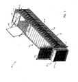
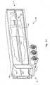
- a material urging system 10 comprises a container structure 11 including floor substructure 15, wall substructures 16, a discharge gate 21 and material urging structure 12.
- Roof 17 includes top opening 18 and top openi.ng cover 19.
- top opening cover 19 and discharge gate 21 are operated by hydraulic rams 20 and 23 respectively.
- Figure 1 shows material urging structure 12 in its fully advanced position projecting through discharge gate opening 22 with discharge gate 21 in its open position.
- material urging structure 12 When material urging structure 12 is in a fully retracted position at rear end 13 of container structure 11, compactable material may be inserted into the container through top opening 18. With the top opening cover 19 closed and discharge gate 21 lowered, material urging structure 12 is driven towards the forward end 14, thereby compacting any material in the container against the discharge gate 21.
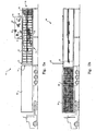
- Figure 2a shows material urging system 10 in loading mode, with side wall substructure and part of internal wall sheeting removed for charity, and where material urging structure 12 is fully retracted at rear end 13 of container structure 11 and compactable material 24 is introduced through top opening 18.
- Figure 2b shows material urging system 10 wi.th side wall substructure 16 removed for clarity, and were compacted material 25 has been ejected through opened di.scharge gate 21 into transport vehicle 26.
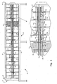
- Figure 3 is a cross section of a wall substructure 16 as viewed from the forward end 14 of container structure 11. It should be noted that the wall substructure 16 and all associated components shown in Figures 3 and 4 are symmetrically duplicated for the opposite side wall of container structure 11 and the mechanism hereinafter described works in unison on both sides of the container structure.
- Wall substructure 16 includes upper frame structure 34 and lower frame structure 35 made up of a plurality of vertical frame members 27 and horizontal frame members 28 (as further illustrated in Figure 4 ). Affixed internally to upper frame structure 34 and lower frame structure 35 are upper wall sheeting portion 30 and lower wall sheeting potion 31 respectively.
- wall sheeting 30 and 31 and frame structures 34 and 35 are separated so as to form a horizontal slot 32 extending substantially for the length of the container structure 11.
- Joining webs 36 are rigidly connected to each corresponding upper and lower vertical frame member 27 to effectively combine upper and lower frame structures 34 and 35 into a unified rigid structure.
- a pair of longitudinal rail members 37 disposed side by side are provided of which the inner rail member is attached to upper wall section vertical frame members 27 and the outer rail member is attached to the joining webs 36.
- Rail members 37 are spaced apart so as to leave a vertical slot 40 between their adjoining sides.
- Rail members 37 extend the length of container structure 11 and are preferably in the form of rectangular section steel tubing.
- the upper, lower and adjoining surfaces of longitudinal rail members 37 are provided with bearing strip material 38.
- I-beam 39 Interposed between adjoining longitudinal rails 37 is an I-beam 39 oriented so that its central web hangs vertically in slot 40 with the underside surfaces of its upper flange supported on the bearing strip material 38 covering the upper surfaces of longitudinal rail members 37.
- the sizes of rail members 37, I-beam 39 and bearing strip material. 38 are so chosen as to allow a sliding fit reciprocating movement of I-beam 39 on rails and bearing strips.
- a main hydraulic ram 42 attached to wall substructure 16 at the ram's passive end 43, and to thrust block 41 at its rod end 44, is adapted to impart the reciprocating movement to I-beam 39.
- Each thrust assembly 46 includes a double ended pawl 48 of which a first end 51 is visible in Figure 3 .
- Pawl 48 is mounted on pivot shaft 50 supported in thrust assembly support 47 and may be rotated about pivot shaft 50 by pawl actuator means 49 so as to bring one of its ends down to the level of slot 32; its other end then having been rotated into a position above and clear of the level of slot 32.
- Material urging structure 12 is adapted to slide on floor 15 and i.s a close sliding fit between internal wall sheeting 29 and roof 17. Each side of material urging structure 12 is provi.ded with projecting lug 45, adapted to extend through slot 32 so as to engage with one end of double ended pawl 48.
- Figure 4 shows a side view of material urging system 10 from which the internal wall sheeting has been omi.tted for clarity.
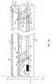
- Material urging structure 12 shown as hatched has been moved towards the discharge gate 21 of container structure 11 to the position shown, by a first extension stroke of hydraulic ram 42 acting on I-beam 39.
- First movement of I-beam 39 was transferred to projecting lug 45 through pawl first end 51a of thrust assembly 46a.
- main ram 42 is in its retracted state ready to move material urging structure 12 a second increment towards the discharge gate by driving pawl end 51b of thrust assembly 46b against projecting lug 45.
- material urging structure 12 is fully in its retracted position at rear end 13 of container structure 11 ( Figure 4 ).
- projecting lug 45 is then forward, (that is towards the forward end 14), of thrust assembly 46a.
- thrust assembly pawl actuator 49a is in retracted mode which has rotated first end 51a of pawl 48a in forward thrust position.
- Main ram 42 now extends for a first compaction stroke, sliding I-beam 39 forward together with thrust assembly 46a, to force lug 45 and hence material urging structure forward to a first incremented position.
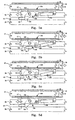
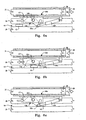
- Hydraulic ram 42 now retracts, to pull I-beam 39 back to its initial position. This requires second thrust assembly 46b to pass the projecting lug 45 as shown in Figure 5b and 5c . This is achieved by de-activating pawl actuator 49b, allowing double ended pawl 48b to rotate about pawl pivot shaft 50b as upwardly sloping face 56b is forced against the lug 45.
- pawl actuator 49b is returned to its retracted position, thus rotating first end 51b of pawl 48b to its forward thrust position as shown in Figure 5d .
- Discharge gate 21 is then opened and the compacted material incrementally advanced until material urging structure 12 reaches its forward limit at forward end 14 of container structure 11, projecting through opened discharge gate 21.
- the material urging structure 12 may be subject to a degree of' "spring-back", especially as maximum compaction is approached towards the end of the compaction process. This can force the urging structure back into a position where the next thrust assembly cannot be retracted back past the projecting lug and hence no further incremental movement of the urging structure is possible.
- material urging structure 12 may be fitted with braking or locking means which are activated during the retraction of I-beam 39 and until the double ended pawls are returned to the forward thrust position.
- main ram 42 does not out-stroke to its full extent, the stroke being controlled by suitable limit switches. This is to allow the furthest forward thrust assembly 46n to be driven just past lug 45, (when second end 52n has been rotated to its reverse thrust position and its actuator i.s de-activated), by a full extension of the main ram 42. After extending pawl actuator 49n to reset second end 52n to the reverse thrust position, the first return increment of material urging structure 12 towards rear end 13 of container structure 11 may be made.
- the incremental advance of the material urging structure towards the forward end of container structure 11 occurs once a quantity of compactable material has been introduced into container structure 11 and both the top opening cover 19 and discharge gate 21 are closed.
- discharge gate 21 is opened and the compacted material ejected by the completion of the incremental advance of the urging structure.
- an optional intermediate compaction gate may be located at some point between the top opening and the discharge gate. This allows smaller quantities of refuse material to be compacted and, once compacted, to be pushed past the intermediate gate. This has the advantage of achieving a higher compaction density of the final compacted load available for transfer to the refuse transport vehicle.
- the construction of the container structure is as that previously described for the First Embodiment above and, as before, both sides of the container structure are symmetrical and carry symmetrical mechanical systems.
- Like features are numbered as for the first embodiment but with the addition of 100 so that for example feature 39 is number 139 in this embodiment and so forth.
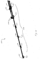
- I-beam 139 is supported by twin longitudinal rail members 137 and is connected to main hydraulic ram 142 via thrust block 141. Attached at intervals along the underside of I-bean 139 are thrust assemblies 146, the end view of one of which, as seen from the forward end of the container structure 111, is shown in Figure 7 .
- thrust assembly 146 is comprised of clevis mount 160 carrying pawl pivot shaft 150 about which rotates double ended pawl 148.
- control bracket 161 which in turn carries control pivot shaft 162.
- control pivot shaft 162 is pivotally connected by means of bearing 163 to control arm 164.
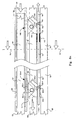
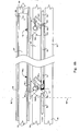
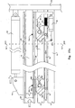
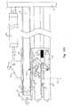
- Control arm 164 similarly connects to each of the control pivot shafts 162 of each of the thrust assemblies 146 whereby reciprocating movements of control arm 164 have the effect of rotating the attitude of double ended pawls 148 between a forwardly incrementing thrust position as in Figure 8a and a rearwardly incrementing thrust position as in Figure 8c.
- Control arm 164 is connected to a pawl control actuator 166 (shown i.n Figure 10a ), such as an hydraulic ram, mounted to I-beam 139 at rear end 113 of container structure 111, so that by the operation of this single actuator, the operating positions of all double ended pawls may be changed in unison.
- a pawl control actuator 166 shown i.n Figure 10a
- I-beam 139 mounted to I-beam 139 at rear end 113 of container structure 111, so that by the operation of this single actuator, the operating positions of all double ended pawls may be changed in unison.
- double ended pawl 148(i+1) is forced to rotate about pawl pivot shaft 150(i+1) as the upwardly sloping face 156(i+1) is forced against projecting lug 145.
- Discharge gate 21 is then opened and the compacted material incrementally advanced until the material urging structure reaches its forward limit at forward end 114 of container structure 111, projecting through opened discharge gate 121.
- urging structure 112 may preferably be fitted with braking or locking means to retain its incremented position while thrust assemblies are being retracted for a next forward increment.
- thrust return block 165 acts on projecting lug 145 and material urging structure 112 is moved a first partial return increment towards the rear end 113 of container structure 111.
- the pawl control actuator now extends to rotate double ended pawls 148n into their return thrust position as shown in Figure 9b .
- pressure released from the pawl control actuator to allow rotation of double ended pawl 148n through contact with the projecting lug 1.45 I-beam 139 is now driven forward, pushing thrust assembly 146n past projecting lug 145.
- the pawl control ram now extends to return double ended pawls 148n into the return thrust position shown in Figure 9c enabling the retraction stroke of I-beam 139 to complete the first return increment of material urging structure 112 towards rear end 113.
- the remaining returning increments are a reverse procedure of the intermediate incrementing sequence described above.
- I-beam 139 is provided at thi.s end with a forward thrust block 167.
- Pawl control actuator 166 retracts to return double ended pawls 148a into their forward thrust position.
- the main ram 142 then extends to complete the first incremental advance of the material urging structure, followed by the intermediate increment sequence described above.
- the container structure may optionally be fitted with an intermediate compaction gate to allow the sequenti.al assembling of a full compacted load from smaller compacted quantities of waste material.
- both the first and the second embodiments described above are directed at compaction and the incremental urging mechanisms act in conjunction with a container structure
- the principle of the mechanisms may be applied for example to drive solid material along a supporting surface.
- the system may be adapted to drive an array of palletized materials or containers along the length of a loading dock for transfer into a transport vehicle.
- the urging mechanisms may be disposed at floor level or recessed into channels along both sides of the dock with the equivalent of the material urging structure adapted to slide on the surface of the loading dock or on suitable friction reducing means such as rails or wheels or a combination of these.
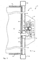
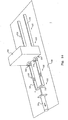
- a container structure similar to that previously described for the first embodiment herein above and shown in figure 1 also comprises a floor substructure, wall substructures, a roof substructure and a discharge gate disposed at a forward end of the container structure. A portion of the rearward end of the present container structure 700 is shown in figure 18 .
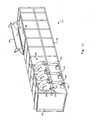
- a material urging structure 600 of the present embodiment shown in figure 15 is preferably of substantially box-shaped construction, having sides 610 and 611, top 612, bottom 613 and front compacting face 614.
- Material urging structure 600 is adapted to substantially traverse the length of the container structure and is dimensioned so as to leave minimal clearance between urging structure 600 and the internal surfaces of the floor, walls and roof substructures of container structure 700.
- the material urging structure 600 Prior to a compaction phase of the material urging system the material urging structure 600 is retracted towards a rearward end 702 (that is the end opposite to the discharge gate) of the container structure 700, at least to an extent that loading of material to be compacted may be introduced into the container structure. This may be accomplished for example through a top opening provided with a top opening cover or through side apertures as previously described.
- the material urging structure 600 is urged into incremental movement in both an advancing and compacting forward direction, that is towards the discharge gate, and a retracting direction, through the interaction of two hydraulically driven mechanical systems; a deriving system and an engagement system.
- the first of these, the driving system includes two identical mechanisms disposed one on each side of the container structure 700.
- each includes an hydraulic ram 651 affixed by mounting bracket 652 to the outside of the side wall substructure 704 at the rearward end 702 of the container structure as best seen in figure 18 .
- Both rams and mechanisms 650 on each side of the container structure are arranged to stroke in unison.
- the piston rod 653 of each ram 651 drives an engagement nest beam 654 extending substantially the length of the container structure 700 and guided, for example by roller elements 655, so as to allow the beam 654 to be driven into horizontal reciprocating motion by its respective ram 651.
- Engagement nest beam 654 is provided with a number of engagement nests 656 rigidly connected to the beam 654 and equi-spaced along the length of the beam; the spacing conforming to the stroke of the ram 651.
- Each nest 655 may take the form of a plate 657 in which is provided an elongate slot 658. These elongate slots 658 then lie along a common horizontal line at a level coi.ncident with the continuous slot 706 in each side wall substructure 704 which extends substantially along the length the container structure as previously described in the first preferred embodi.ment above.
- the second mechanical system that is the engagement system mechanism 615, is shown in figure 15 and is incorporated within the material urging structure 600.
- a first thrust tongue plate 616 and second thrust tongue plate 617 are slidably supported between horizontal guide rails 618 and 619 and between upper and lower guide plates 620 and 621.
- Each thrust tongue plate 616 and 617 is pivotally connected to a linkage arm 622 and 623 respectively which in turn are pivotally connected to a central pivot arm 624.
- Central pivot arm 624 is arranged to rotate about fixed vertical pivot axi.s 625 mounted between support plates 626.
- first thrust tongue plate 616 and second thrust tongue plate 617 Mounted to and between the inner ends of first thrust tongue plate 616 and second thrust tongue plate 617 is a thrust tongue hydraulic ram 627. It will be clear that by means of the mechanism of linkage arms 622 and 623 and central pivot arm 624, first thrust tongue plate 616 and second thrust tongue plate 617 will retract inwardly when thrust tongue hydraulic ram 627 in-strokes and extend outwardly to the position shown in figure 17 when the thrust tongue hydraulic ram 627 out-strokes.
- first and second thrust tongues 616 and 617 project through slots 628 and 629 in the sides of material urging structure 600. These slots are positioned to coincide with the continuous slot 706 in each side wall substructures 704 of the container structure 700 when urging structure 600 is installed.
- Second mechanism 615 is further provided with first and second retainer tongue plates 630 and 631, each of which is urged into reciprocal motion by hydraulic rams 632 and 633 respectively.
- first and second retainer tongue plates 630 and 631 project through slots in the sides of material urging structure 600 as can be seen in figure 15 (second retainer tongue 631 is hidden from view).
- Each si.de wall substructure 704 of the container structure 700 is provided with a series of retainer slots 708 as shown in figure 18 arranged below the continuous slot 706 in the side wall of the container structure and adapted to coincide with the positions of first and second retainer tongue plates 630 and 631 when material urging structure 600 is at each of incremented positions along the length of the container structure.
- the interval between successive retainer slots is equal to the spacing of engagement nests 655 and the stroke of the rams 651.
- surging structure 600 is shown at an intermediate position between two incremented locations.
- the slots 706 are sized to accept the insertion of retainer tongue plates 630 and 631 as a sliding fit so as to lock material urging structure 600 into a currently incremented position.
- rams 651 are initially in an in-stroked condition.
- First and second thrust tongues 616 and 617 axe then urged into an outwardly extended position by the out-stroking of thrust tongue hydraulic ram 627 so as to project through the continuous slots in the side walls of the container structure and engage with coinciding slots 658 of engagement nests 656 of each of the driving system engagement nest beams 654.
- first and second retainer tongues 630 and 631 are retracted from engagement with their respective coinciding retainer slots 708.
- the driving system rams 651 then out-stroke to drive material urging structure 600 into a next advanced position where retainer tongues 630 and 631 are urged outwardly to engage with the corresponding retainer slots 708 in the side walls. This prevents any partial retraction of the material urging structure 600 which may be induced by the reaction force of compressed material between material urging structure and the discharge gate.
- the first and second thrust tongues 616 and 617 are now retracted from their engaged position with the slots 658 of nests 656 of the engagement nest beams 654 thus allowing the rams 651 of the driving mechanical system 650 to detract. This brings the next forward nests 656 of the engagement nest beams 654 into coincidence with the thrust tongue positions of the material urging structure to allow for a further incrementing cycle.
- the discharge gate may be opened when the material urging structure 600 has reached a position relative to the engagement nests 656 where the compression of the material between the discharge gate and the material urging structure has reached a desired degree. This will generally occur well before the most forwardly incremented position available.
- suffici.ent material is loaded into the container structure, and that point of desired compressi.on achieved, when the volume of the compressed material is approximately equal to that of a transport vehicle brought into alignment with the container structure at the discharge end.
- Further forward increments of the material urging structure may then be used to drive the compressed volume of material into the transport vehicle through the opened discharge gate.
- the last forward stroke of the primary system and the configuration of the material urging structure are such that the material urging structure projects sufficiently through the discharge gate to fully drive a load of compacted material into an abutting transport vehicle.
- first and second thrust tongue plates 616 and 617 remain engaged with their respective nests and the subsequent in-strokes of the primary system rams 651 then constitute the first retraction of the material urging structure 600.
- Further retraction cycles may be effected by sequences of retraction of first and second thrust tongue plates, out-stroking of the primary system rams and re-engagement of the first and second thrust tongue plates with the next coincident nests of the engagement nest beams. Since there is no reaction force of compressed material acting on the material urging structure, the use of the first and second retainer tongues during retraction is not required.
Landscapes
- Engineering & Computer Science (AREA)
- Mechanical Engineering (AREA)
- Reciprocating Conveyors (AREA)
- Refuse Collection And Transfer (AREA)
- Vehicle Body Suspensions (AREA)
- Fluid-Pressure Circuits (AREA)
- Fluid-Driven Valves (AREA)
- Road Paving Machines (AREA)
- Refuse-Collection Vehicles (AREA)
- Filling Or Emptying Of Bunkers, Hoppers, And Tanks (AREA)
Claims (9)
- Un système de compactage de matière meuble (10) comprenant :(a) une structure formant conteneur (11) ayant une extrémité arrière (13) et une extrémité avant (14),(b) une structure de propulsion de matière (12),(c) des moyens d'activation de structure de propulsion de matière dans lequel ladite structure de propulsion de matière est avancée de façon incrémentielle d'une position rétractée au niveau de ladite extrémité arrière de ladite structure formant conteneur, en direction de ladite extrémité avant de ladite structure formant conteneur, où ladite extrémité avant est une extrémité de décharge,de la matière meuble (24) insérée dans ladite structure formant conteneur (11) qui est compactée par ladite structure de propulsion de matière (12) en un volume compacté (25) contre une porte de décharge (21) au niveau de ladite extrémité de décharge, ledit système étant caractérisé en ce que chaque substructure formant paroi latérale dudit conteneur est pourvue d'une fente s'étendant substantiellement sur la longueur de ladite substructure formant paroi latérale, dans lequel ladite structure de propulsion de matière (12) est pourvue de chaque côté de ladite structure d'une patte faisant saillie, chacune desdites pattes faisant saillie à travers une desdites fentes, lesdites pattes se mettant en prise avec des moyens d'activation à va-et-vient disposés le long de chaque dite substructure formant paroi latérale.
- Le système de compactage de matière meuble (10) de la revendication 1 dans lequel ladite structure formant conteneur (11) inclut ;(a) une substructure formant plancher,(b) lesdites substructures formant parois latérales,(c) un toit,(d) une ouverture de dessus,(e) une couverture d'ouverture de dessus,(f) un moyen de fermeture d'extrémité de décharge.
- Le système de compactage de matière meuble (10) de la revendication 2, dans lequel ladite structure de propulsion de matière (12) est rétractée de façon incrémentielle par lesdits moyens d'activation de ladite extrémité de décharge (14) vers ladite extrémité arrière (13) de ladite structure formant conteneur (11).
- Le système de compactage de matière meuble (10) de la revendication 3, dans lequel lesdits moyens d'activation fonctionnent substantiellement à l'unisson.
- Le système de compactage de matière meuble (10) de la revendication 4, dans lequel la structure de propulsion de matière (12) est un emboîtement étroit par coulissement au sein de ladite structure formant conteneur (11), ladite structure de propulsion de matière étant adaptée pour coulisser sur la surface de ladite substructure formant plancher.
- Le système de compactage de matière meuble (10) de la revendication 4, dans lequel chaque fente fournit une séparation entre une portion supérieure et une portion inférieure de blindage de paroi interne.
- Le système de compactage de matière meuble (10) de la revendication 6, dans lequel chacune desdites fentes est colinéaire avec un système de rail, ledit système de rail étant adapté pour supporter et guider lesdits moyens d'activation, chacun desdits moyens d'activation comprenant une poutre à va-et-vient.
- Le système de compactage de matière meuble (10) de la revendication 7, dans lequel ladite poutre à va-et-vient est pourvue d'une pluralité d'assemblages de poussée, lesdits assemblages de poussée étant disposés à intervalles substantiellement égaux sur la longueur de ladite poutre, entre une extrémité avant et une extrémité arrière de ladite poutre.
- Le système de compactage de matière meuble (10) de la revendication 7, dans lequel ladite poutre à va-et-vient est propulsée dans un mouvement de va-et-vient par un vérin hydraulique raccordé de façon à pivoter au niveau d'une première extrémité dudit vérin à ladite poutre à va-et-vient et au niveau d'une deuxième extrémité dudit vérin à ladite structure formant conteneur (11).
Applications Claiming Priority (3)
| Application Number | Priority Date | Filing Date | Title |
|---|---|---|---|
| AUPS1251A AUPS125102A0 (en) | 2002-03-21 | 2002-03-21 | Improved compactor system |
| AU2002001251 | 2002-03-21 | ||
| PCT/AU2003/000349 WO2003080481A1 (fr) | 2002-03-21 | 2003-03-21 | Systeme de compactage de matieres par petits pas |
Publications (3)
| Publication Number | Publication Date |
|---|---|
| EP1497206A1 EP1497206A1 (fr) | 2005-01-19 |
| EP1497206A4 EP1497206A4 (fr) | 2008-11-19 |
| EP1497206B1 true EP1497206B1 (fr) | 2011-01-26 |
Family
ID=3834848
Family Applications (1)
| Application Number | Title | Priority Date | Filing Date |
|---|---|---|---|
| EP03707910A Expired - Lifetime EP1497206B1 (fr) | 2002-03-21 | 2003-03-21 | Systeme de compactage de matieres par petits pas |
Country Status (11)
| Country | Link |
|---|---|
| US (2) | US7419348B2 (fr) |
| EP (1) | EP1497206B1 (fr) |
| JP (1) | JP4557554B2 (fr) |
| CN (1) | CN1655999A (fr) |
| AT (1) | ATE496853T1 (fr) |
| AU (2) | AUPS125102A0 (fr) |
| CA (1) | CA2479832C (fr) |
| DE (1) | DE60335870D1 (fr) |
| NZ (1) | NZ536018A (fr) |
| WO (1) | WO2003080481A1 (fr) |
| ZA (1) | ZA200408457B (fr) |
Cited By (1)
| Publication number | Priority date | Publication date | Assignee | Title |
|---|---|---|---|---|
| CN104773103A (zh) * | 2014-01-09 | 2015-07-15 | 姚天锡 | 一种步进推送式自卸车 |
Families Citing this family (34)
| Publication number | Priority date | Publication date | Assignee | Title |
|---|---|---|---|---|
| AUPS125102A0 (en) * | 2002-03-21 | 2002-04-18 | Byrne Trailer Manufacturing (Wagga Wagga) Pty Limited | Improved compactor system |
| US7172382B2 (en) * | 2004-10-12 | 2007-02-06 | Nathan Frankel | Loading assembly for transport containers, and related method of use |
| US7588406B2 (en) | 2004-10-12 | 2009-09-15 | Fastek, Llc | Loading assembly for transport containers, and related method of use |
| AT502675B1 (de) * | 2006-02-21 | 2007-05-15 | Maraton Maschb Gmbh | Vorrichtung zur gärgutbeschickung einer gäranlage |
| US8668425B2 (en) | 2007-03-05 | 2014-03-11 | SA Recycling LLC | Methods and apparatus for freight container loading |
| US7837428B2 (en) | 2007-03-05 | 2010-11-23 | SA Recycling LLC | Methods and apparatuses for freight container loading |
| US7744330B2 (en) | 2008-06-13 | 2010-06-29 | Blue Tee Corporation | Container packer system and method |
| US9056731B1 (en) | 2008-06-13 | 2015-06-16 | Advanced Steel Recovery, Llc | Container packer system and method |
| US8282148B2 (en) * | 2008-12-30 | 2012-10-09 | Titan Trailers, Inc. | Convertible trailer |
| US8371434B2 (en) * | 2009-07-23 | 2013-02-12 | Balanced Enterprise Solutions, Llc | Conveyor assembly |
| US8784031B2 (en) * | 2010-01-04 | 2014-07-22 | Container Stuffers, Llc | Cargo loader |
| US20120291639A1 (en) * | 2011-05-16 | 2012-11-22 | Ryan Thomas Blankenship | External Cylinder Packer Head |
| US9156611B1 (en) * | 2011-08-31 | 2015-10-13 | Paul Campbell | Front loading garbage truck |
| US9738464B1 (en) | 2012-10-18 | 2017-08-22 | Scott Sakajian | System and method for protecting containers from damage during loading |
| US9697598B2 (en) | 2012-11-23 | 2017-07-04 | Koninklijke Philips N.V. | Generating a key-image from a medical image |
| US20150027791A1 (en) * | 2013-07-24 | 2015-01-29 | Ingersoll Machine Tools, Inc. | Vertical Load Weighing Station for Large Machinery Guide Systems |
| US9359154B2 (en) | 2013-10-28 | 2016-06-07 | Michael Jason Grady | Transfer trailer for loading bales of forage into a transport vehicle |
| CN104192599B (zh) * | 2014-08-26 | 2018-02-06 | 广州明森科技股份有限公司 | 一种智能卡输送装置中的推卡机构 |
| US9643526B2 (en) | 2014-12-09 | 2017-05-09 | Somerset Welding & Steel, Inc. | Horizontal ejector truck body |
| CN105253395A (zh) * | 2015-10-19 | 2016-01-20 | 瑞安市恺鸿包装机械有限公司 | 一种包装机的多工位加料设备 |
| CN106994931A (zh) * | 2016-01-26 | 2017-08-01 | 姚天锡 | 插拔桩式步进推送自卸车 |
| CN107672967B (zh) * | 2016-08-01 | 2021-05-14 | 郭吉平 | 一种可全程自动清洗的垃圾水平长距离推送装置 |
| KR101867922B1 (ko) * | 2017-04-10 | 2018-07-19 | 김성춘 | 암롤 박스 덮개 |
| DE202017103126U1 (de) * | 2017-05-23 | 2018-08-24 | Heinz Bergmann Gmbh | Stationäre Abfallpresseneinheit zur Verbindung mit einem Wechselcontainer |
| CN107971480B (zh) * | 2017-12-19 | 2023-11-21 | 浙江省机电设计研究院有限公司 | 一种带缓冲功能的挡箱机及其工作方法 |
| CN114074808A (zh) * | 2020-08-11 | 2022-02-22 | 广州嘉天保洁服务有限公司 | 垃圾转运车 |
| CN112693698B (zh) * | 2020-12-10 | 2022-09-02 | 黑龙江工业学院 | 一种用于英语教材制备的自动包装机构 |
| US11866074B2 (en) | 2021-04-19 | 2024-01-09 | Shiloh Williams | Belly dump trailer with conveyors for moving material |
| IT202100024542A1 (it) * | 2021-09-24 | 2023-03-24 | Teuman S R L | Pressa per compattare materiale di rifiuto con dispositivo di traslazione e relativo metodo |
| IT202100026516A1 (it) * | 2021-10-15 | 2023-04-15 | Teuman S R L | Pressa per compattare materiale di rifiuto con apparato anti-schiacciamento e relativo metodo |
| CN114311789B (zh) * | 2021-12-16 | 2024-03-26 | 湖南领湃达志科技股份有限公司 | 一种锂电池电极的加工装置 |
| CN114275414B (zh) * | 2022-01-06 | 2022-10-18 | 上海金桥(集团)有限公司 | 一种多功能地埋垃圾箱总成 |
| CN114772179B (zh) * | 2022-05-24 | 2024-05-31 | 华核电气股份有限公司 | 一种板材输送装置 |
| CN119706424A (zh) * | 2024-12-31 | 2025-03-28 | 焦作科瑞森重装股份有限公司 | 一种循环步进式堆料机 |
Family Cites Families (35)
| Publication number | Priority date | Publication date | Assignee | Title |
|---|---|---|---|---|
| US3422973A (en) * | 1966-10-11 | 1969-01-21 | Sidney E Longman | Sugarcane planting aid |
| US3561624A (en) | 1968-12-16 | 1971-02-09 | Jimmie V Thurmond | Transfer station equipment for refuse disposal |
| US3799374A (en) * | 1971-11-01 | 1974-03-26 | S Weaver | Trash compactor container |
| US3759406A (en) * | 1971-11-30 | 1973-09-18 | R Nickel | Packing door for refuse truck |
| GB1369982A (en) | 1971-12-03 | 1974-10-09 | Glover Webb Liversidge Ltd | Containers |
| US3765321A (en) * | 1971-12-03 | 1973-10-16 | Sno Pac Corp | Apparatus for aiding disposal of snow by compacting it to great density |
| JPS4957328U (fr) * | 1972-08-23 | 1974-05-21 | ||
| JPS4995467A (fr) * | 1973-01-13 | 1974-09-10 | ||
| JPS5243289B2 (fr) * | 1973-02-19 | 1977-10-29 | ||
| SE392448B (sv) * | 1974-12-09 | 1977-03-28 | Norba Ab | Anordning foer inmatning av avfall eller dylikt i en samlingsbehallare |
| AU501513B2 (en) | 1975-01-24 | 1979-06-21 | Ja Baker | Transportation container |
| CA1037998A (fr) * | 1976-04-26 | 1978-09-05 | Diesel Equipment Limited | Camion a benne basculante telescopique |
| US4371306A (en) * | 1978-02-10 | 1983-02-01 | Sargent Industries, Inc. | Refuse ejection apparatus |
| US4145824A (en) * | 1978-03-13 | 1979-03-27 | Watson William D | Snow compactor |
| US4359307A (en) * | 1980-10-15 | 1982-11-16 | Strick Corporation | Vehicle for transporting compressible materials |
| US4627783A (en) * | 1983-01-21 | 1986-12-09 | Quinto De Filippi | Refuse disposal apparatus and vehicle |
| FR2542715B1 (fr) * | 1983-03-16 | 1987-11-06 | Saphem | Dispositif de compactage, notamment du contenu d'une caisse de semi-remorque de grande capacite |
| US4578015A (en) * | 1983-06-16 | 1986-03-25 | Baldarelli Bros., Inc. | Truck body with pull-off door |
| JPS61206701A (ja) * | 1985-03-07 | 1986-09-13 | 新明和工業株式会社 | 廃棄物押込装置における押込板の作動制御装置 |
| US4729304A (en) | 1986-04-03 | 1988-03-08 | Norwood Enterprises | Refuse compactor and transfer chamber |
| US4877366A (en) * | 1988-04-22 | 1989-10-31 | Quinto De Filippi | Refuse vehicle |
| US4941796A (en) * | 1988-04-29 | 1990-07-17 | Quinto De Filippi | Front loading refuse vehicle |
| US4923356A (en) * | 1988-05-03 | 1990-05-08 | Foster Raymond K | Apparatus for collecting and compacting garbage and then loading it into a road vehicle |
| US5314290A (en) | 1991-10-04 | 1994-05-24 | Lutz David E | Cargo carrying vehicle having a movable bulkhead located therein |
| US5238359A (en) * | 1991-12-04 | 1993-08-24 | Chen Chin Lung | Garbage truck |
| US5247880A (en) * | 1992-03-26 | 1993-09-28 | Marathon Equipment Company | Horizontal baler with movable bottom support ejector |
| AU699054B2 (en) * | 1994-07-27 | 1998-11-19 | Anthony Paul Ahrens | Transfer apparatus |
| US5527147A (en) | 1994-10-31 | 1996-06-18 | Altamont, Inc. | Waste handling method and apparatus for transferring waste from collection vehicles to transfer trailers |
| DE69725503D1 (de) * | 1996-05-30 | 2003-11-20 | Eugene Mcmahon | Ballenpresse |
| US6234739B1 (en) * | 1997-05-16 | 2001-05-22 | Wayne Engineering Corporation | Compaction mechanism for refuse and recyclables collection vehicles |
| US6138557A (en) | 1999-02-23 | 2000-10-31 | Marathon Equipment Company | Method and apparatus for measuring the length of a waste log and/or weight of waste log while compacting and transferring the waste log for transport |
| JP2001039204A (ja) * | 1999-07-28 | 2001-02-13 | Yukikazu Saito | 貨物自動車の積荷の搬入、搬出装置 |
| US6632066B1 (en) * | 1999-09-06 | 2003-10-14 | Koshiji Kinzoku Co., Ltd. | Carrying and loading/unloading apparatus |
| US6497547B1 (en) * | 1999-12-29 | 2002-12-24 | Nicholas J. Maglaras | Containerized refuse collection truck |
| AUPS125102A0 (en) | 2002-03-21 | 2002-04-18 | Byrne Trailer Manufacturing (Wagga Wagga) Pty Limited | Improved compactor system |
-
2002
- 2002-03-21 AU AUPS1251A patent/AUPS125102A0/en not_active Abandoned
-
2003
- 2003-03-21 DE DE60335870T patent/DE60335870D1/de not_active Expired - Lifetime
- 2003-03-21 AT AT03707910T patent/ATE496853T1/de not_active IP Right Cessation
- 2003-03-21 WO PCT/AU2003/000349 patent/WO2003080481A1/fr not_active Ceased
- 2003-03-21 CN CNA038116774A patent/CN1655999A/zh active Pending
- 2003-03-21 JP JP2003578256A patent/JP4557554B2/ja not_active Expired - Fee Related
- 2003-03-21 EP EP03707910A patent/EP1497206B1/fr not_active Expired - Lifetime
- 2003-03-21 US US10/508,747 patent/US7419348B2/en not_active Expired - Fee Related
- 2003-03-21 AU AU2003212099A patent/AU2003212099B2/en not_active Expired - Fee Related
- 2003-03-21 NZ NZ536018A patent/NZ536018A/en not_active IP Right Cessation
- 2003-03-21 CA CA2479832A patent/CA2479832C/fr not_active Expired - Fee Related
-
2004
- 2004-10-19 ZA ZA2004/08457A patent/ZA200408457B/en unknown
-
2006
- 2006-05-04 US US11/418,936 patent/US7488148B2/en not_active Expired - Fee Related
Cited By (1)
| Publication number | Priority date | Publication date | Assignee | Title |
|---|---|---|---|---|
| CN104773103A (zh) * | 2014-01-09 | 2015-07-15 | 姚天锡 | 一种步进推送式自卸车 |
Also Published As
| Publication number | Publication date |
|---|---|
| ATE496853T1 (de) | 2011-02-15 |
| WO2003080481A1 (fr) | 2003-10-02 |
| EP1497206A4 (fr) | 2008-11-19 |
| JP4557554B2 (ja) | 2010-10-06 |
| US20050191158A1 (en) | 2005-09-01 |
| US20070098531A2 (en) | 2007-05-03 |
| JP2005520755A (ja) | 2005-07-14 |
| US7488148B2 (en) | 2009-02-10 |
| US20070012202A1 (en) | 2007-01-18 |
| CA2479832C (fr) | 2010-11-09 |
| AU2003212099B2 (en) | 2008-03-20 |
| US7419348B2 (en) | 2008-09-02 |
| CN1655999A (zh) | 2005-08-17 |
| NZ536018A (en) | 2005-02-25 |
| AUPS125102A0 (en) | 2002-04-18 |
| ZA200408457B (en) | 2005-12-28 |
| CA2479832A1 (fr) | 2003-10-02 |
| DE60335870D1 (de) | 2011-03-10 |
| EP1497206A1 (fr) | 2005-01-19 |
| AU2003212099A1 (en) | 2003-10-08 |
Similar Documents
| Publication | Publication Date | Title |
|---|---|---|
| AU2003212099B2 (en) | Incremental material urging system | |
| US20240317489A1 (en) | Front and side loading packers for electric refuse vehicle | |
| US6224317B1 (en) | Front end loader adapter | |
| US4923356A (en) | Apparatus for collecting and compacting garbage and then loading it into a road vehicle | |
| US5044870A (en) | Method for collecting and compacting garbage and then loading it into a road vehicle | |
| DE2535998B2 (de) | Müllfahrzeug mit Frontlader | |
| US6193295B1 (en) | Refuse collection vehicle | |
| DE3537546A1 (de) | Mehrkammer-abfallsammelfahrzeug | |
| AU2008202736B2 (en) | Incremental material urging system | |
| US3942430A (en) | Trash compactor | |
| CN121063112A (zh) | 一种新型垃圾容器箱门锁紧机构及其解闭锁机构 | |
| US5752439A (en) | Reconfigurable vertical compactor | |
| CN117446427B (zh) | 单组驱动器驱使物料装载箱移动的装置 | |
| US4990048A (en) | Apparatus for collecting and compacting garbage and then loading it into a road vehicle | |
| US3687313A (en) | Plunger shield for refuse vehicle loading chamber | |
| JPS5974801A (ja) | 固形物の圧縮積込み装置 | |
| US20060127208A1 (en) | Cyclic traveling apparatus and method | |
| EP0363621B1 (fr) | Presse pour compacter des éléments radioactifs de structure oblongue et procédé pour son utilisation | |
| EP0181440B1 (fr) | Récipient de grandes dimensions pour le transport d'ordures | |
| DE4301566C1 (de) | Müllsammelfahrzeug und Verfahren zum kraftvollen Verschließen eines Wechsel-Sammelbehälters auf einem Müllsammelfahrzeug | |
| DE3431116C2 (fr) | ||
| CN221295459U (zh) | 集装箱的移动式翻转装置 | |
| DE3131544C2 (fr) | ||
| SU859247A1 (ru) | Устройство дл транспортировки мусора | |
| DE2300636A1 (de) | Muellbehaelter |
Legal Events
| Date | Code | Title | Description |
|---|---|---|---|
| PUAI | Public reference made under article 153(3) epc to a published international application that has entered the european phase |
Free format text: ORIGINAL CODE: 0009012 |
|
| 17P | Request for examination filed |
Effective date: 20041021 |
|
| AK | Designated contracting states |
Kind code of ref document: A1 Designated state(s): AT BE BG CH CY CZ DE DK EE ES FI FR GB GR HU IE IT LI LU MC NL PT RO SE SI SK TR |
|
| AX | Request for extension of the european patent |
Extension state: AL LT LV MK |
|
| RAP1 | Party data changed (applicant data changed or rights of an application transferred) |
Owner name: ALEXANDRIA NOMINEES PTY LTD |
|
| A4 | Supplementary search report drawn up and despatched |
Effective date: 20081016 |
|
| 17Q | First examination report despatched |
Effective date: 20090220 |
|
| GRAP | Despatch of communication of intention to grant a patent |
Free format text: ORIGINAL CODE: EPIDOSNIGR1 |
|
| GRAS | Grant fee paid |
Free format text: ORIGINAL CODE: EPIDOSNIGR3 |
|
| GRAA | (expected) grant |
Free format text: ORIGINAL CODE: 0009210 |
|
| AK | Designated contracting states |
Kind code of ref document: B1 Designated state(s): AT BE BG CH CY CZ DE DK EE ES FI FR GB GR HU IE IT LI LU MC NL PT RO SE SI SK TR |
|
| AX | Request for extension of the european patent |
Extension state: AL LT LV MK |
|
| REG | Reference to a national code |
Ref country code: GB Ref legal event code: FG4D |
|
| REG | Reference to a national code |
Ref country code: CH Ref legal event code: EP |
|
| REG | Reference to a national code |
Ref country code: IE Ref legal event code: FG4D |
|
| REF | Corresponds to: |
Ref document number: 60335870 Country of ref document: DE Date of ref document: 20110310 Kind code of ref document: P |
|
| REG | Reference to a national code |
Ref country code: DE Ref legal event code: R096 Ref document number: 60335870 Country of ref document: DE Effective date: 20110310 |
|
| REG | Reference to a national code |
Ref country code: NL Ref legal event code: VDEP Effective date: 20110126 |
|
| LTIE | Lt: invalidation of european patent or patent extension |
Effective date: 20110126 |
|
| PG25 | Lapsed in a contracting state [announced via postgrant information from national office to epo] |
Ref country code: ES Free format text: LAPSE BECAUSE OF FAILURE TO SUBMIT A TRANSLATION OF THE DESCRIPTION OR TO PAY THE FEE WITHIN THE PRESCRIBED TIME-LIMIT Effective date: 20110507 Ref country code: GR Free format text: LAPSE BECAUSE OF FAILURE TO SUBMIT A TRANSLATION OF THE DESCRIPTION OR TO PAY THE FEE WITHIN THE PRESCRIBED TIME-LIMIT Effective date: 20110427 Ref country code: SE Free format text: LAPSE BECAUSE OF FAILURE TO SUBMIT A TRANSLATION OF THE DESCRIPTION OR TO PAY THE FEE WITHIN THE PRESCRIBED TIME-LIMIT Effective date: 20110126 Ref country code: PT Free format text: LAPSE BECAUSE OF FAILURE TO SUBMIT A TRANSLATION OF THE DESCRIPTION OR TO PAY THE FEE WITHIN THE PRESCRIBED TIME-LIMIT Effective date: 20110526 |
|
| PG25 | Lapsed in a contracting state [announced via postgrant information from national office to epo] |
Ref country code: CY Free format text: LAPSE BECAUSE OF FAILURE TO SUBMIT A TRANSLATION OF THE DESCRIPTION OR TO PAY THE FEE WITHIN THE PRESCRIBED TIME-LIMIT Effective date: 20110126 Ref country code: BG Free format text: LAPSE BECAUSE OF FAILURE TO SUBMIT A TRANSLATION OF THE DESCRIPTION OR TO PAY THE FEE WITHIN THE PRESCRIBED TIME-LIMIT Effective date: 20110426 Ref country code: SI Free format text: LAPSE BECAUSE OF FAILURE TO SUBMIT A TRANSLATION OF THE DESCRIPTION OR TO PAY THE FEE WITHIN THE PRESCRIBED TIME-LIMIT Effective date: 20110126 Ref country code: NL Free format text: LAPSE BECAUSE OF FAILURE TO SUBMIT A TRANSLATION OF THE DESCRIPTION OR TO PAY THE FEE WITHIN THE PRESCRIBED TIME-LIMIT Effective date: 20110126 Ref country code: AT Free format text: LAPSE BECAUSE OF FAILURE TO SUBMIT A TRANSLATION OF THE DESCRIPTION OR TO PAY THE FEE WITHIN THE PRESCRIBED TIME-LIMIT Effective date: 20110126 Ref country code: BE Free format text: LAPSE BECAUSE OF FAILURE TO SUBMIT A TRANSLATION OF THE DESCRIPTION OR TO PAY THE FEE WITHIN THE PRESCRIBED TIME-LIMIT Effective date: 20110126 Ref country code: FI Free format text: LAPSE BECAUSE OF FAILURE TO SUBMIT A TRANSLATION OF THE DESCRIPTION OR TO PAY THE FEE WITHIN THE PRESCRIBED TIME-LIMIT Effective date: 20110126 |
|
| PG25 | Lapsed in a contracting state [announced via postgrant information from national office to epo] |
Ref country code: EE Free format text: LAPSE BECAUSE OF FAILURE TO SUBMIT A TRANSLATION OF THE DESCRIPTION OR TO PAY THE FEE WITHIN THE PRESCRIBED TIME-LIMIT Effective date: 20110126 Ref country code: MC Free format text: LAPSE BECAUSE OF NON-PAYMENT OF DUE FEES Effective date: 20110331 Ref country code: DK Free format text: LAPSE BECAUSE OF FAILURE TO SUBMIT A TRANSLATION OF THE DESCRIPTION OR TO PAY THE FEE WITHIN THE PRESCRIBED TIME-LIMIT Effective date: 20110126 |
|
| REG | Reference to a national code |
Ref country code: CH Ref legal event code: PL |
|
| PG25 | Lapsed in a contracting state [announced via postgrant information from national office to epo] |
Ref country code: SK Free format text: LAPSE BECAUSE OF FAILURE TO SUBMIT A TRANSLATION OF THE DESCRIPTION OR TO PAY THE FEE WITHIN THE PRESCRIBED TIME-LIMIT Effective date: 20110126 Ref country code: CZ Free format text: LAPSE BECAUSE OF FAILURE TO SUBMIT A TRANSLATION OF THE DESCRIPTION OR TO PAY THE FEE WITHIN THE PRESCRIBED TIME-LIMIT Effective date: 20110126 Ref country code: RO Free format text: LAPSE BECAUSE OF FAILURE TO SUBMIT A TRANSLATION OF THE DESCRIPTION OR TO PAY THE FEE WITHIN THE PRESCRIBED TIME-LIMIT Effective date: 20110126 |
|
| PLBE | No opposition filed within time limit |
Free format text: ORIGINAL CODE: 0009261 |
|
| STAA | Information on the status of an ep patent application or granted ep patent |
Free format text: STATUS: NO OPPOSITION FILED WITHIN TIME LIMIT |
|
| 26N | No opposition filed |
Effective date: 20111027 |
|
| REG | Reference to a national code |
Ref country code: IE Ref legal event code: MM4A |
|
| PG25 | Lapsed in a contracting state [announced via postgrant information from national office to epo] |
Ref country code: LI Free format text: LAPSE BECAUSE OF NON-PAYMENT OF DUE FEES Effective date: 20110331 Ref country code: CH Free format text: LAPSE BECAUSE OF NON-PAYMENT OF DUE FEES Effective date: 20110331 Ref country code: IE Free format text: LAPSE BECAUSE OF NON-PAYMENT OF DUE FEES Effective date: 20110321 |
|
| REG | Reference to a national code |
Ref country code: DE Ref legal event code: R097 Ref document number: 60335870 Country of ref document: DE Effective date: 20111027 |
|
| PG25 | Lapsed in a contracting state [announced via postgrant information from national office to epo] |
Ref country code: IT Free format text: LAPSE BECAUSE OF FAILURE TO SUBMIT A TRANSLATION OF THE DESCRIPTION OR TO PAY THE FEE WITHIN THE PRESCRIBED TIME-LIMIT Effective date: 20110126 |
|
| PG25 | Lapsed in a contracting state [announced via postgrant information from national office to epo] |
Ref country code: LU Free format text: LAPSE BECAUSE OF NON-PAYMENT OF DUE FEES Effective date: 20110321 |
|
| PG25 | Lapsed in a contracting state [announced via postgrant information from national office to epo] |
Ref country code: TR Free format text: LAPSE BECAUSE OF FAILURE TO SUBMIT A TRANSLATION OF THE DESCRIPTION OR TO PAY THE FEE WITHIN THE PRESCRIBED TIME-LIMIT Effective date: 20110126 |
|
| PG25 | Lapsed in a contracting state [announced via postgrant information from national office to epo] |
Ref country code: HU Free format text: LAPSE BECAUSE OF FAILURE TO SUBMIT A TRANSLATION OF THE DESCRIPTION OR TO PAY THE FEE WITHIN THE PRESCRIBED TIME-LIMIT Effective date: 20110126 |
|
| REG | Reference to a national code |
Ref country code: FR Ref legal event code: PLFP Year of fee payment: 14 |
|
| REG | Reference to a national code |
Ref country code: FR Ref legal event code: PLFP Year of fee payment: 15 |
|
| PGFP | Annual fee paid to national office [announced via postgrant information from national office to epo] |
Ref country code: FR Payment date: 20170324 Year of fee payment: 15 Ref country code: DE Payment date: 20170321 Year of fee payment: 15 |
|
| PGFP | Annual fee paid to national office [announced via postgrant information from national office to epo] |
Ref country code: GB Payment date: 20170317 Year of fee payment: 15 |
|
| REG | Reference to a national code |
Ref country code: DE Ref legal event code: R119 Ref document number: 60335870 Country of ref document: DE |
|
| GBPC | Gb: european patent ceased through non-payment of renewal fee |
Effective date: 20180321 |
|
| PG25 | Lapsed in a contracting state [announced via postgrant information from national office to epo] |
Ref country code: DE Free format text: LAPSE BECAUSE OF NON-PAYMENT OF DUE FEES Effective date: 20181002 |
|
| PG25 | Lapsed in a contracting state [announced via postgrant information from national office to epo] |
Ref country code: GB Free format text: LAPSE BECAUSE OF NON-PAYMENT OF DUE FEES Effective date: 20180321 |
|
| PG25 | Lapsed in a contracting state [announced via postgrant information from national office to epo] |
Ref country code: FR Free format text: LAPSE BECAUSE OF NON-PAYMENT OF DUE FEES Effective date: 20180331 |