EP1497476B1 - Verfahren zum abdecken von kühlungsöffnungen eines gasturbinenbauteils - Google Patents
Verfahren zum abdecken von kühlungsöffnungen eines gasturbinenbauteils Download PDFInfo
- Publication number
- EP1497476B1 EP1497476B1 EP03704155A EP03704155A EP1497476B1 EP 1497476 B1 EP1497476 B1 EP 1497476B1 EP 03704155 A EP03704155 A EP 03704155A EP 03704155 A EP03704155 A EP 03704155A EP 1497476 B1 EP1497476 B1 EP 1497476B1
- Authority
- EP
- European Patent Office
- Prior art keywords
- cooling holes
- mask material
- coating
- component
- external surface
- Prior art date
- Legal status (The legal status is an assumption and is not a legal conclusion. Google has not performed a legal analysis and makes no representation as to the accuracy of the status listed.)
- Expired - Lifetime
Links
Images
Classifications
-
- F—MECHANICAL ENGINEERING; LIGHTING; HEATING; WEAPONS; BLASTING
- F01—MACHINES OR ENGINES IN GENERAL; ENGINE PLANTS IN GENERAL; STEAM ENGINES
- F01D—NON-POSITIVE DISPLACEMENT MACHINES OR ENGINES, e.g. STEAM TURBINES
- F01D5/00—Blades; Blade-carrying members; Heating, heat-insulating, cooling or antivibration means on the blades or the members
- F01D5/12—Blades
- F01D5/28—Selecting particular materials; Particular measures relating thereto; Measures against erosion or corrosion
- F01D5/288—Protective coatings for blades
-
- C—CHEMISTRY; METALLURGY
- C23—COATING METALLIC MATERIAL; COATING MATERIAL WITH METALLIC MATERIAL; CHEMICAL SURFACE TREATMENT; DIFFUSION TREATMENT OF METALLIC MATERIAL; COATING BY VACUUM EVAPORATION, BY SPUTTERING, BY ION IMPLANTATION OR BY CHEMICAL VAPOUR DEPOSITION, IN GENERAL; INHIBITING CORROSION OF METALLIC MATERIAL OR INCRUSTATION IN GENERAL
- C23C—COATING METALLIC MATERIAL; COATING MATERIAL WITH METALLIC MATERIAL; SURFACE TREATMENT OF METALLIC MATERIAL BY DIFFUSION INTO THE SURFACE, BY CHEMICAL CONVERSION OR SUBSTITUTION; COATING BY VACUUM EVAPORATION, BY SPUTTERING, BY ION IMPLANTATION OR BY CHEMICAL VAPOUR DEPOSITION, IN GENERAL
- C23C14/00—Coating by vacuum evaporation, by sputtering or by ion implantation of the coating forming material
- C23C14/04—Coating on selected surface areas, e.g. using masks
- C23C14/042—Coating on selected surface areas, e.g. using masks using masks
-
- C—CHEMISTRY; METALLURGY
- C23—COATING METALLIC MATERIAL; COATING MATERIAL WITH METALLIC MATERIAL; CHEMICAL SURFACE TREATMENT; DIFFUSION TREATMENT OF METALLIC MATERIAL; COATING BY VACUUM EVAPORATION, BY SPUTTERING, BY ION IMPLANTATION OR BY CHEMICAL VAPOUR DEPOSITION, IN GENERAL; INHIBITING CORROSION OF METALLIC MATERIAL OR INCRUSTATION IN GENERAL
- C23C—COATING METALLIC MATERIAL; COATING MATERIAL WITH METALLIC MATERIAL; SURFACE TREATMENT OF METALLIC MATERIAL BY DIFFUSION INTO THE SURFACE, BY CHEMICAL CONVERSION OR SUBSTITUTION; COATING BY VACUUM EVAPORATION, BY SPUTTERING, BY ION IMPLANTATION OR BY CHEMICAL VAPOUR DEPOSITION, IN GENERAL
- C23C16/00—Chemical coating by decomposition of gaseous compounds, without leaving reaction products of surface material in the coating, i.e. chemical vapour deposition [CVD] processes
- C23C16/04—Coating on selected surface areas, e.g. using masks
- C23C16/042—Coating on selected surface areas, e.g. using masks using masks
-
- C—CHEMISTRY; METALLURGY
- C23—COATING METALLIC MATERIAL; COATING MATERIAL WITH METALLIC MATERIAL; CHEMICAL SURFACE TREATMENT; DIFFUSION TREATMENT OF METALLIC MATERIAL; COATING BY VACUUM EVAPORATION, BY SPUTTERING, BY ION IMPLANTATION OR BY CHEMICAL VAPOUR DEPOSITION, IN GENERAL; INHIBITING CORROSION OF METALLIC MATERIAL OR INCRUSTATION IN GENERAL
- C23C—COATING METALLIC MATERIAL; COATING MATERIAL WITH METALLIC MATERIAL; SURFACE TREATMENT OF METALLIC MATERIAL BY DIFFUSION INTO THE SURFACE, BY CHEMICAL CONVERSION OR SUBSTITUTION; COATING BY VACUUM EVAPORATION, BY SPUTTERING, BY ION IMPLANTATION OR BY CHEMICAL VAPOUR DEPOSITION, IN GENERAL
- C23C4/00—Coating by spraying the coating material in the molten state, e.g. by flame, plasma or electric discharge
- C23C4/01—Selective coating, e.g. pattern coating, without pre-treatment of the material to be coated
-
- C—CHEMISTRY; METALLURGY
- C25—ELECTROLYTIC OR ELECTROPHORETIC PROCESSES; APPARATUS THEREFOR
- C25D—PROCESSES FOR THE ELECTROLYTIC OR ELECTROPHORETIC PRODUCTION OF COATINGS; ELECTROFORMING; APPARATUS THEREFOR
- C25D5/00—Electroplating characterised by the process; Pretreatment or after-treatment of workpieces
- C25D5/02—Electroplating of selected surface areas
- C25D5/022—Electroplating of selected surface areas using masking means
-
- C—CHEMISTRY; METALLURGY
- C25—ELECTROLYTIC OR ELECTROPHORETIC PROCESSES; APPARATUS THEREFOR
- C25D—PROCESSES FOR THE ELECTROLYTIC OR ELECTROPHORETIC PRODUCTION OF COATINGS; ELECTROFORMING; APPARATUS THEREFOR
- C25D7/00—Electroplating characterised by the article coated
-
- F—MECHANICAL ENGINEERING; LIGHTING; HEATING; WEAPONS; BLASTING
- F01—MACHINES OR ENGINES IN GENERAL; ENGINE PLANTS IN GENERAL; STEAM ENGINES
- F01D—NON-POSITIVE DISPLACEMENT MACHINES OR ENGINES, e.g. STEAM TURBINES
- F01D5/00—Blades; Blade-carrying members; Heating, heat-insulating, cooling or antivibration means on the blades or the members
- F01D5/005—Repairing methods or devices
-
- B—PERFORMING OPERATIONS; TRANSPORTING
- B23—MACHINE TOOLS; METAL-WORKING NOT OTHERWISE PROVIDED FOR
- B23P—METAL-WORKING NOT OTHERWISE PROVIDED FOR; COMBINED OPERATIONS; UNIVERSAL MACHINE TOOLS
- B23P2700/00—Indexing scheme relating to the articles being treated, e.g. manufactured, repaired, assembled, connected or other operations covered in the subgroups
- B23P2700/06—Cooling passages of turbine components, e.g. unblocking or preventing blocking of cooling passages of turbine components
-
- F—MECHANICAL ENGINEERING; LIGHTING; HEATING; WEAPONS; BLASTING
- F05—INDEXING SCHEMES RELATING TO ENGINES OR PUMPS IN VARIOUS SUBCLASSES OF CLASSES F01-F04
- F05D—INDEXING SCHEME FOR ASPECTS RELATING TO NON-POSITIVE-DISPLACEMENT MACHINES OR ENGINES, GAS-TURBINES OR JET-PROPULSION PLANTS
- F05D2230/00—Manufacture
- F05D2230/80—Repairing, retrofitting or upgrading methods
-
- F—MECHANICAL ENGINEERING; LIGHTING; HEATING; WEAPONS; BLASTING
- F05—INDEXING SCHEMES RELATING TO ENGINES OR PUMPS IN VARIOUS SUBCLASSES OF CLASSES F01-F04
- F05D—INDEXING SCHEME FOR ASPECTS RELATING TO NON-POSITIVE-DISPLACEMENT MACHINES OR ENGINES, GAS-TURBINES OR JET-PROPULSION PLANTS
- F05D2230/00—Manufacture
- F05D2230/90—Coating; Surface treatment
-
- F—MECHANICAL ENGINEERING; LIGHTING; HEATING; WEAPONS; BLASTING
- F05—INDEXING SCHEMES RELATING TO ENGINES OR PUMPS IN VARIOUS SUBCLASSES OF CLASSES F01-F04
- F05D—INDEXING SCHEME FOR ASPECTS RELATING TO NON-POSITIVE-DISPLACEMENT MACHINES OR ENGINES, GAS-TURBINES OR JET-PROPULSION PLANTS
- F05D2260/00—Function
- F05D2260/20—Heat transfer, e.g. cooling
- F05D2260/202—Heat transfer, e.g. cooling by film cooling
Definitions
- the invention relates to a process of masking cooling holes of a gas turbine component according to the preamble of claim 1.
- Components such as gas turbine blades, vanes and other cooled parts often contain cavities that distribute cooling air to a plurality of holes in the wall of the part that lead to the outer surface.
- Most turbine components are coated for protection from oxidation and/or corrosion with, for example, a MCrAlY coating (base coat) and some are also coated with a thermal barrier coating (TBC) for thermal insulation.
- base coat MCrAlY coating
- TBC thermal barrier coating
- the re-application of the coatings can be very problematic for parts with a large number of cooling holes.
- the base coat can reach thicknesses of 150-300 ⁇ m, and the TBC may be another 200 - 500 ⁇ m in thickness.
- the coatings are usually first and then the holes are drilled directly through the coatings and the wall thickness of the component. However, during the repair operations the holes are already in place, including during re-coating. The combined thicknesses of these coatings would have a very significant (and negative) influence on the effectiveness of the cooling holes if the coatings were deposited into these holes during re-coating, especially considering that some holes are 1 mm or less in diameter.
- US-A-5,702,288 One disclosure which offers a solution to this is US-A-5,702,288 , in which an abrasive slurry is injected into the cavity of the component and forced through the cooling holes which were partially covered by the coating material. There was no welding or brazing closed prior to coating. However this also abrades the internal cooling configuration (ribs), any inserts, and also the non-coated portion of the cooing holes. In addition, it would not be possible to use this process on a stator vane which contained a cooling air distribution insert, without first removing the insert. This would be time consuming and very expensive. Another version of this technique is disclosed in US-A-5,702,288 .
- a further disclosure in which all holes are plugged at once is given in US-A-5,800,695 .
- a masking agent is placed into the cooling configuration and forced through until it fills the cooling holes from the inside, but only up to the level of the exterior surface of the component.
- a coating is then applied, in this case electrolytically applied platinum. Due to the non-conductivity of the plastic maskant cited in the disclosure, no Pt would deposit on the masking agent in the cooling holes.
- US-A-6,004,620 discloses a technique in which the coating is applied to the component as normal, over the open and unprotected cooling holes. Then a high pressure water jet originating from the inside of the component cleans the cooling holes of unwanted coating build-up.
- This invention was originally destined for combustors - large conical components for which implementing this technique is feasible. However, it would be nearly impossible to insert a high pressure water jet device into the cooling configuration of a turbine blade. In stator vanes this only would be feasible, if the cooling air distributing insert is first removed.
- US-A-5,216,808 discloses the use of a pulsed ultraviolet laser to remove the unwanted TBC from within the cooling holes (after coating the component with unprotected cooling holes), since the wavelength of the UV laser is particularly well absorbed by the material used to make TBC's (namely zirconium oxide).
- this method is not effective at removing unwanted MCrAlY in the cooling holes since the absorption of the radiation by the MCrAlY is not nearly as efficient as with the TBC.
- This invention recognizes the problem of extreme filling of the cooling holes with TBC material, as it includes the use of "machine vision" which locates the holes based on a datum in a CAD (computer aided design) file. A CNC positioning device then is used to properly locate the part relative to the laser, and then cleaning of the cooling holes is performed automatically according to the recorded positions of the cooling holes in the CNC data.
- a masking agent may also be used to protect the inner portion of the cooling hole from chemical attack.
- the disadvantage of this is that it requires a heat treatment at high temperature to create the diffusion zone, and those skilled in the art know that all such high temperature heat treatments degrade the microstructure of the alloy used for most gas turbine components. Further more, as admitted in the disclosure, not all the holes will be uniformly affected, but it is hoped that the overall distribution of cooling air flows will be within originally intended manufacturing tolerances (therefore this introduces uncertainty into the final temperature distribution of the component in the engine, which is highly undesirable).
- Each disclosure had a different method of providing this: one by using a polymerizing energy source from the interior of the component, which is difficult to realize for many component designs and the other by providing a preform from wax, and then filing this with a polymerizing mask agent which, after hardening, provides the desired protrusions.
- EP-A-1 076 106 discloses a method of masking cooling holes of a gas turbine component comprising applying a mask material to the cooling holes, exposing the cooling holes to at least one energy source and thereby thickening the mask material, removing mask material unaffected by the energy source from the external surface of the component coating the component and the masked cooling holes and removing thickened mask material from the cooling holes.
- EP-A-843 026 discloses a method of masking cooling holes of a gas turbine comprising injecting a maskant into the cooling passages to fill the cooling holes with a maskant, plating the external surface of the component with a coating and removing the maskant from the component.
- the cooling holes are filled so that the maskant is flush with the surface of the component.
- injecting the maskant care should be taken that the maskant is not present on surfaces intended to be coated. Any maskant that is present on the outside of the component is generally removed before plating.
- This invention is particularly suited to prevent the filling beyond desired limits of the cooling holes in gas turbine blades and stator vanes with a coating applied by thermal spray, electrolytic deposition, or other deposition means.
- a process was found of masking cooling holes of a gas turbine component with an external surface, comprising a cavity and a plurality of cooling holes, before coating the gas turbine component, comprising the steps of
- the polymer mask material when it contained an appropriate mixture of fillers, could be filled into the cooling holes only up to the exterior surface of the component and still adequately protect the cooling holes from being filled with coating material.
- This made unnecessary the arduous task of providing polymerizing energy from the inside of the component, which is sometimes impossible, and/or providing a wax shape on the exterior of the part, into which the mask material would be filled and hardened, in order to provide a protrusion of mask material beyond the exterior surface of the component prior to the coating operation.
- the proper selection of mask material and filler material ensured non-sticking of the coating material to the mask.
- the filler material is selected from particles or fibres of metal, oxide material such as silica, magnesia, calcia, alumina, zirconia, yttria or a mixture there of, which provided adequate wear and thermal resistance in the range of 5 to 95 vol.-% and in a preferred range of 20 - 90 vol.-%.
- Metallic fillers, other oxide fillers, organic materials or endothermic fillers said endothermic fillers including carbonate compounds or mixtures thereof are also possible.
- the mask material can be applied to the cooling holes from the external surface which consumed far less of the polymer compare to any of the prior art using such mask materials in which either the entire cooling configuration had to be filled with polymer, or the entire component had to be dipped in polymer. Still one embodiment is to apply the mask material from an internal cavity of the component.
- An energy source can be placed from the outside of the component so that the energy impinges directly on said mask material which plugs the cooling holes.
- the component may be heated or cooled before or during processing.
- a water jet could be used to remove any residual coating which is in the cooling holes. This step can be done manually, or by locating the cooling holes using a three dimensional vision system which directs a CNC machine using the same program to drill the cooling holes in the first place.
- the mask material can be a UV polymerizing plastic such as polyurethane, a polyurethane oligomer mixture, poly(isobutyl methacrylate), poly(vinyl toluene), polyproplyene or a polypropylene / polyurethane oligomer mixture, the class of polymers vetones or silicones, or any photopolymerizing resin or mixture of resins.
- a UV polymerizing plastic such as polyurethane, a polyurethane oligomer mixture, poly(isobutyl methacrylate), poly(vinyl toluene), polyproplyene or a polypropylene / polyurethane oligomer mixture, the class of polymers vetones or silicones, or any photopolymerizing resin or mixture of resins.
- the thickened mask material containing the filler material may further be heated so as to volatilize or otherwise remove the organic portion of the mask material before the coating is deposited.
- the mask material is thickened by an energy source, which may be electromagnetic such as visible, ultraviolet or infra-red light or collimated light such as laser.
- electromagnetic such as visible, ultraviolet or infra-red light or collimated light such as laser.
- the disclosed method of mask the cooling holes according to the present invention can be first applied for the deposition of a bond coating (MCrAlY) and then, subsequently, used for the application of a ceramic coating (TBC) on top of the bond coating (MCrAlY).
- a bond coating MrAlY
- TBC ceramic coating
- the coating could be applied e.g. by at least one of the coating methods of plasma spray, wire arc spray, high velocity oxy-fuel (HVOF), air plasma spray (APS), low pressure plasma spray (LPPS), vacuum plasma spray (VPS), electrolytic or galvanic deposition, Physical Vapour Deposition (PVD), Chemical Vapour Deposition (CVD) or any other suitable methods known in the prior art.
- HVOF high velocity oxy-fuel
- APS air plasma spray
- LPPS low pressure plasma spray
- VPS vacuum plasma spray
- electrolytic or galvanic deposition Physical Vapour Deposition (PVD), Chemical Vapour Deposition (CVD) or any other suitable methods known in the prior art.
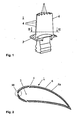
- Figure 1 shows a component 1 such as blades or vanes of gas turbine engines comprising a cavity 2, not visible in figure 1 , and cooling holes 4, which are on the external surface 6 of the component 1 as well as on the platform 3 of the component 1.
- the present invention relates to a process of masking cooling holes 4 in the component 1 before the deposition of coating material on the external surface 6 of the component 1 will take place.
- FIG. 1 shows a section through the component 1.
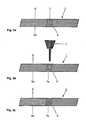
- the component 1 comprising a cavity 2 and three cooling holes 4.
- the number of the cooling holes 4 is given only as an example and may vary on the purpose the component 1 is used for.
- the component 1 has an external surface 6 and an internal surface 6a.
- the figure 3a shows the first step of the process according to the invention.
- the cooling holes 4 are masked with the mask material 5. It will be coated with, sprayed with, or immersed in a material which is at least partially liquid, the mask material 5, and which thickens, which means to become more viscous or solid when exposed to an energy source 7.
- a way it may be done is to inject the mask material 5 into the cooling cavity 2 of the component 1 and force it through the cooling holes 4.
- Excess mask material 5 may be removed afterwards from the external and the internal surface 6, 6a (which can be the cavity 2 or one side of the platform 3 not to be coated) of the component 1 before the application of an energy source 7.
- one advantageous embodiment is to apply to mask material 5 from the external surface 6.
- mask material 5 different substances may be used:
- fillers were required to impart the mask materials 5 with thermal resistance and impact resistance to the spraying process used to deposit the MCrAlY coating and/or TBC.
- One of the possible ceramic fillers tried was particles or fibres of metal, oxide material such as silica, magnesia, calcia, alumina, zirconia, yttria or a mixture there of, which provided adequate wear and thermal resistance.
- Metallic fillers, other oxide fillers or organic materials are also possible.
- Figures 3b shows the second step of the process according the invention of at least partially thickening the mask material 5.
- a desired energy source 7 will be placed from the outside of the component 1 so that the energy impinges directly on said mask material 5 which is in the cooling holes 4.
- Figures 3b shows the thickened material 5a as well.
- Different energy sources 7 may be used in order to obtain the desirable result:
- the mask material 5a thickened from the energy source 7 containing the filler material may further be heated so as to volatilize or otherwise remove the organic portion of the thickened mask material 5a before the coating 8 is deposited on external surface 6 of the component 1.
- this invention also made unnecessary the providing of excess polymerizing liquid over the cooling holes 4, for the purpose of providing enough material to produce the protrusion of mask material 5 beyond the external surface 5 of the component 1.
- the masking operation has become much more simple, rapid and cheap.
- the application of the polymerizing material from the external surface 6 of the component 1 prevented complications of plugging in the cooling configuration, or restricted flow through a cooling air distribution insert.
- the addition of the polymer from the outer surface of the component via syringe or spatula consumed far less of the polymer compare to any of the prior art such as US-B1-6,265,022 or US-A-4,743,462 using such mask materials 5 in which either the entire cooling configuration had to be filled with polymer, or the entire component 1 had to be dipped in polymer.
- an endothermic material is added as filler material to the polymer in order to provide additional protection from the heat transferred during coating.
- sodium bicarbonate decomposes in a highly endothermic reaction, which absorbs the heat imparted to the mask material 5 during coating.
- the filler content is in the range of 5 to 95 vol.-% and in a preferred range of 20 - 90 vol.-%, at least in the upper most portion of the mask material 5 in the cooling hole 4.
- the mask material 5 at the portion of the cooling hole 4 exit at the external surface 6 of the component 1 contains 45 - 90 vol.-% of the filler material to a depth not less than 1 mm.
- the cooling holes 4 are sufficiently long that they do not require complete filling, but only partial filling in a way that the upper portion closest to the external surface 6 is filled to provide the desired result.
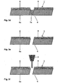
- the application of the coating 8 on the external surface 6 will take place directly on the masked cooling holes 4 with the means known in the state of the art.
- this could be MCrAlY and/or TBC applied e.g. by at least one of the coating methods of plasma spray, wire arc spray, high velocity oxy-fuel (HVOF), air plasma spray (APS), low pressure plasma spray (LPPS), vacuum plasma spray (VPS), electrolytic or galvanic deposition, Physical Vapour Deposition (PVD), Chemical Vapour Deposition (CVD) or any other suitable methods known in the prior art.
- HVOF high velocity oxy-fuel
- APS air plasma spray
- LPPS low pressure plasma spray
- VPS vacuum plasma spray
- electrolytic or galvanic deposition Physical Vapour Deposition (PVD), Chemical Vapour Deposition (CVD) or any other suitable methods known in the prior art.
- PVD Physical Vapour Deposition
- CVD Chemical Vapour Deposition
- the thickened mask material 5a will be removed to reveal cooling holes 4 essentially free of coating material 8. This is shown in figure 3e .
- the removal of the thickening organic mask material 5a can be accomplished by heating the part to 600°C in a vacuum furnace for 2 hours.
- a water jet 9 (as shown in Figure 3f ) could be used to remove any residual coating 8 which is in the cooling holes 4. This step can be done manually, or by locating the cooling holes 4 using a three dimensional vision system which directs a CNC machine using the same program to drill the cooling holes 4 in the first place.
- the component 1 may be heated or cooled before or during processing to facilitate the application and/or hardening of at least a portion of the mask material 5.
- the polymer was hardened using a 365 nm UV light lamp with an intensity of 150 mW/cm 2 , with a cure time of approximately 50 seconds. It was helpful to orient the light in a direction parallel to the direction of the cooling holes to ensure optimal absorption and hardening. Excess material on the surface of the vanes was removed after hardening with light grit blasting. The vanes were prepared for HVOF by coarse grit blasting, heating to 100 - 200°C, and coating of approximately 200 - 400 ⁇ m thickness of a standard MCrAlY coating. After coating the excess mask material remaining in the cooling holes is removed by heating the components to 300 - 650°C to burn off the remaining.
- TBC Thermal Barrier Coating
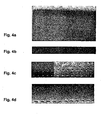
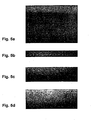
- Fig. 5a-d shows the appearance of airfoil cooling holes that were masked before each coating operation
- Fig. 6a-d shows the appearance of the cooling holes with no masking applied.
- Airflow data was taken from the cooling holes row by row, in the state with original coating, and then with new coating.
- the holes with masking averaged within +/-10% of the original airflow values, while the holes without masking averaged 80-100% underflow, where 100% underflow represents complete blockage of the holes.
Landscapes
- Chemical & Material Sciences (AREA)
- Engineering & Computer Science (AREA)
- Materials Engineering (AREA)
- Mechanical Engineering (AREA)
- Chemical Kinetics & Catalysis (AREA)
- Metallurgy (AREA)
- Organic Chemistry (AREA)
- General Engineering & Computer Science (AREA)
- Electrochemistry (AREA)
- General Chemical & Material Sciences (AREA)
- Physics & Mathematics (AREA)
- Plasma & Fusion (AREA)
- Turbine Rotor Nozzle Sealing (AREA)
- Structures Of Non-Positive Displacement Pumps (AREA)
- Laser Beam Processing (AREA)
- Coating By Spraying Or Casting (AREA)
Claims (18)
- Verfahren zum Abdecken von Kühlungsöffnungen (4) eines Gasturbinenbauteils (1), wobei das Gasturbinenbauteil (1) eine äußere Oberfläche (6), einen Hohlraum (2) und mehrere Kühlungsöffnungen (4) umfaßt, wobei das Verfahren die folgenden Schritte umfaßt:(a) Aufbringen eines fotopolymerisierenden Abdeckmaterials (5) auf die Kühlungsöffnungen (4), so daß die Kühlungsöffnungen (4) zumindest teilweise mit dem Abdeckmaterial in dem der äußeren Oberfläche (6) am nächsten liegenden Abschnitt und im wesentlichen bis zu einer Höhe der äußeren Oberfläche (6) gefüllt werden, wobei das Abdeckmaterial (5) in mindestens einem an der äußeren Oberfläche (6) des Bauteils (1) liegenden Abschnitt mit einem Füllmaterial gemischt ist, wobei das Aufbringen das schrittweise Aufbringen des Abdeckmaterials umfaßt einschließlich mindestens teilweise Eindicken des Abdeckmaterials vor dem Aufbringen einer nächsten Menge in den Kühlungsöffnungen und Ändern der Menge von Füllstoff von Schicht zu Schicht von Abdeckmaterial, wobei die oberste Schicht die größte Menge an Füllmaterial aufweist,(b) mindestens teilweises Eindicken mindestens eines Abschnitts des Abdeckmaterials (5a) innerhalb der Kühlungsöffnungen (4), wobei das Abdeckmaterial (5) unter Verwendung einer elektromagnetischen Strahlung eingedickt wird, die direkt auf das Abdeckmaterial in den Kühlungsöffnungen von außerhalb des Bauteils (1) auftrifft,(c) Beschichten der äußeren Oberfläche (6) des Bauteils (1) und der abgedeckten Kühlungsöffnungen (4) und(d) Entfernen des verbleibenden eingedickten Abdeckmaterials (5a) von den Kühlungsöffnungen (4).
- Verfahren nach Anspruch 1, wobei das Abdeckmaterial (5) von der äußeren Oberfläche (6) des Bauteils (1) auf die Kühlungsöffnungen (4) aufgebracht wird.
- Verfahren nach Anspruch 1, wobei das Abdeckmaterial (5) von einem inneren Hohlraum (2) des Bauteils (1) auf die Kühlungsöffnungen (4) aufgebracht wird.
- Verfahren nach Anspruch 1, wobei nach dem Aufbringen des Abdeckmaterials (5) und vor dem Beschichten die äußere Oberfläche (6) durch mechanische Mittel gereinigt wird, um restliches Abdeckmaterial (5) zu entfernen.
- Verfahren nach Anspruch 1, wobei das Bauteil (1) vor oder während des Verfahrens erhitzt oder gekühlt wird, um das Aufbringen und/oder Eindicken mindestens einen Abschnitts des Abdeckmaterials (5) zu erleichtern.
- Verfahren nach Anspruch 1, wobei das Abdeckmaterial (5) an dem Abschnitt, wo die Kühlungsöffnungen (4) an der äußeren Oberfläche (6) des Bauteils (1) austreten, 45-90 Vol.-% Füllmaterial bis zu einer Tiefe von mindestens 1 mm enthält.
- Verfahren nach einem der Ansprüche 1 bis 6, wobei die dem Abdeckmaterial (5) zugesetzten Füllstoffe Teilchen oder Fasern aus Metall, Oxidmaterial wie etwa Siliciumoxid, Magnesia, Calciumoxid, Aluminiumoxid, Zirkoniumoxid, Yttriumoxid oder einer Mischung davon und organischen Materialien enthalten.
- Verfahren nach einem Ansprüche 1 bis 7, wobei endotherme Füllstoffe dem Abdeckmaterial (5) zugesetzt werden, wobei die endothermen Füllstoffe Carbonatverbindungen oder Mischungen davon enthalten.
- Verfahren nach Anspruch 7 oder 8, wobei der Füllstoffgehalt im Bereich von 5-95 Vol.-% liegt.
- Verfahren nach Anspruch 9, wobei der Füllstoffgehalt im Bereich von 20-90 Vol.-% liegt.
- Verfahren nach einem der Ansprüche 1 bis 10, wobei das Entfernen etwaigen restlichen Beschichtungsmaterials (8) in den Kühlungsöffnungen (4) durch maschinelle Wasserstrahlbearbeitung abgeschlossen wird.
- Verfahren nach Anspruch 11, wobei etwaiges restliches Beschichtungsmaterial (8) in den Kühlungsöffnungen (4) entfernt wird durch Lokalisieren der Kühlungsöffnungen (4) unter Verwendung eines Sichtsystems, das eine CNC-Maschine leitet.
- Verfahren nach einem der Ansprüche 1 bis 12, wobei das Abdeckmaterial ein UV-polymerisierender Kunststoff ist wie etwa Polyurethan, eine Polyurethan-Oligomer-Mischung, Poly(isobutyl-methacrylat), Poly(vinyltoluol), Polypropylen oder eine Polypropylen/Polyurethan-Oligomer-Mischung, die Klasse der Polymere, Ketone oder Silikone oder ein beliebiges fotopolymerisierendes Harz oder Mischung von Harzen.
- Verfahren nach Anspruch 13, wobei das das Füllmaterial enthaltende eingedickte Abdeckmaterial (5a) erhitzt oder verarbeitet wird, um den organischen Anteil des Abdeckmaterials (5) zu verdampfen oder anderweitig zu entfernen, bevor die Beschichtung (8) auf der äußeren Oberfläche (6) des Bauteils (1) abgeschieden wird.
- Verfahren nach Anspruch 14, wobei in dem Abdeckmaterial (5) Bindemittel enthalten sind, die die festen Teilchen oder Fasern des Füllmaterials effektiv zusammenhalten, nachdem der organische Anteil des Abdeckmaterials (5) entfernt ist.
- Verfahren nach einem der Ansprüche 1 bis 15, wobei das Abdeckmaterial (5) durch elektromagnetische Strahlung im sichtbaren, Ultraviolett- oder Infrarotbereich oder eine kollimierte Lichtquelle eingedickt wird.
- Verfahren nach einem der Ansprüche 1 bis 16, wobei in Schritt (c) des Anspruchs 1 zuerst eine Haftungsbeschichtung (MCrAlY) abgeschieden und danach eine Keramikbeschichtung (TBC) auf der Haftungsbeschichtung (MCrAlY) abgeschieden wird.
- Verfahren nach einem der Ansprüche 1 bis 17, wobei mindestens eines der folgenden Beschichtungsverfahren zum Aufbringen der Beschichtung verwendet wird: Plasmasprühen, Wire Arc Spray, HVOF (High Velocity Oxy-Fuel), Luftplasmasprühen (APS), Niederdruckplasmasprühen (LPPS), Vakuumplasmasprühen (VPS), elektrolytische oder galvanische Abscheidung, physikalische Abscheidung aus der Dampfphase (PVD), chemische Abscheidung aus der Dampfphase (CVD).
Priority Applications (1)
| Application Number | Priority Date | Filing Date | Title |
|---|---|---|---|
| EP03704155A EP1497476B1 (de) | 2002-04-04 | 2003-03-12 | Verfahren zum abdecken von kühlungsöffnungen eines gasturbinenbauteils |
Applications Claiming Priority (4)
| Application Number | Priority Date | Filing Date | Title |
|---|---|---|---|
| EP02405266A EP1350860A1 (de) | 2002-04-04 | 2002-04-04 | Verfahren zum Abdecken von Kühlungsöffnungen eines Gasturbinebauteils |
| EP02405266 | 2002-04-04 | ||
| PCT/CH2003/000163 WO2003089679A1 (en) | 2002-04-04 | 2003-03-12 | Process of masking cooling holes of a gas turbine component |
| EP03704155A EP1497476B1 (de) | 2002-04-04 | 2003-03-12 | Verfahren zum abdecken von kühlungsöffnungen eines gasturbinenbauteils |
Publications (2)
| Publication Number | Publication Date |
|---|---|
| EP1497476A1 EP1497476A1 (de) | 2005-01-19 |
| EP1497476B1 true EP1497476B1 (de) | 2008-08-06 |
Family
ID=27838208
Family Applications (2)
| Application Number | Title | Priority Date | Filing Date |
|---|---|---|---|
| EP02405266A Withdrawn EP1350860A1 (de) | 2002-04-04 | 2002-04-04 | Verfahren zum Abdecken von Kühlungsöffnungen eines Gasturbinebauteils |
| EP03704155A Expired - Lifetime EP1497476B1 (de) | 2002-04-04 | 2003-03-12 | Verfahren zum abdecken von kühlungsöffnungen eines gasturbinenbauteils |
Family Applications Before (1)
| Application Number | Title | Priority Date | Filing Date |
|---|---|---|---|
| EP02405266A Withdrawn EP1350860A1 (de) | 2002-04-04 | 2002-04-04 | Verfahren zum Abdecken von Kühlungsöffnungen eines Gasturbinebauteils |
Country Status (8)
| Country | Link |
|---|---|
| US (1) | US7147899B2 (de) |
| EP (2) | EP1350860A1 (de) |
| JP (1) | JP2005522633A (de) |
| AT (1) | ATE403760T1 (de) |
| AU (1) | AU2003206605A1 (de) |
| CA (1) | CA2481111C (de) |
| DE (1) | DE60322690D1 (de) |
| WO (1) | WO2003089679A1 (de) |
Cited By (1)
| Publication number | Priority date | Publication date | Assignee | Title |
|---|---|---|---|---|
| RU2718877C2 (ru) * | 2018-02-26 | 2020-04-15 | Федеральное государственное бюджетное образовательное учреждение высшего образования "Ухтинский государственный технический университет" | Способ нанесения функционально-ориентированного износостойкого покрытия на лопатку газотурбинного двигателя |
Families Citing this family (55)
| Publication number | Priority date | Publication date | Assignee | Title |
|---|---|---|---|---|
| EP1350860A1 (de) | 2002-04-04 | 2003-10-08 | ALSTOM (Switzerland) Ltd | Verfahren zum Abdecken von Kühlungsöffnungen eines Gasturbinebauteils |
| EP1352989A1 (de) * | 2002-04-10 | 2003-10-15 | Siemens Aktiengesellschaft | Bauteil mit einer Maskierungsschicht |
| US6875476B2 (en) * | 2003-01-15 | 2005-04-05 | General Electric Company | Methods and apparatus for manufacturing turbine engine components |
| EP1582694A1 (de) * | 2004-04-02 | 2005-10-05 | Siemens Aktiengesellschaft | Verfahren zum Schützen von Öffnungen eines Bauteils bei einem Bearbeitungsprozess |
| US20050217110A1 (en) * | 2004-04-06 | 2005-10-06 | Topal Valeriy I | Deposition repair of hollow items |
| EP1712739A1 (de) | 2005-04-12 | 2006-10-18 | Siemens Aktiengesellschaft | Bauteil mit Filmkühlloch |
| DE102005041844A1 (de) * | 2005-09-02 | 2007-03-08 | Mtu Aero Engines Gmbh | Verfahren zum Beschichten oder Entschichten eines Bauteils |
| EP1772594A1 (de) * | 2005-10-04 | 2007-04-11 | Siemens Aktiengesellschaft | Verfahren zum Schützen von Öffnungen eines Bauteils bei einem Bearbeitungsprozess gegen ein Eindringen von Material und Polysiloxan enthaltende keramische Zusammensetzung |
| CA2568971A1 (en) * | 2005-11-29 | 2007-05-29 | General Electric Company | Method for applying a bond coat and a thermal barrier coating over an aluminided surface |
| DE102006010929B4 (de) * | 2006-03-09 | 2013-10-02 | Mtu Aero Engines Gmbh | Beschichtungsverfahren |
| EP1835045A1 (de) * | 2006-03-15 | 2007-09-19 | Siemens Aktiengesellschaft | Verfahren zur Herstellung eines beschichteten Bauteils |
| US7622160B2 (en) * | 2006-07-28 | 2009-11-24 | General Electric Company | Method for concurrent thermal spray and cooling hole cleaning |
| WO2008138384A1 (de) * | 2007-05-16 | 2008-11-20 | Siemens Aktiengesellschaft | Materialzusammensetzung zur verwendung als maskierungsmaterial zum schutz von nicht zu beschichtenden bereichen eines turbinenbauteils und verfahren zum beschichten von turbinenbauteilen |
| US7988412B2 (en) * | 2007-08-24 | 2011-08-02 | General Electric Company | Structures for damping of turbine components |
| US8173218B2 (en) * | 2007-10-24 | 2012-05-08 | United Technologies Corporation | Method of spraying a turbine engine component |
| GB2461898B (en) * | 2008-07-17 | 2010-09-08 | Rolls Royce Plc | Combustion apparatus |
| US8661826B2 (en) | 2008-07-17 | 2014-03-04 | Rolls-Royce Plc | Combustion apparatus |
| GB2461897B (en) * | 2008-07-17 | 2010-11-03 | Rolls Royce Plc | Combustion apparatus |
| US20110171394A1 (en) * | 2008-08-26 | 2011-07-14 | Allen David B | Method of making a combustion turbine component using thermally sprayed transient liquid phase forming layer |
| EP2213759A1 (de) * | 2009-01-08 | 2010-08-04 | Siemens Aktiengesellschaft | Verfahren zum Beschichten eines Bauteils mit Filmkühllöchern, und Bauteil |
| PL2322683T3 (pl) | 2009-11-16 | 2020-12-14 | Siemens Aktiengesellschaft | Sposób powlekania komponentu z częściowo zamkniętymi otworami i sposób otwierania otworów |
| US9181819B2 (en) | 2010-06-11 | 2015-11-10 | Siemens Energy, Inc. | Component wall having diffusion sections for cooling in a turbine engine |
| US20120087803A1 (en) * | 2010-10-12 | 2012-04-12 | General Electric Company | Curved film cooling holes for turbine airfoil and related method |
| US20120167389A1 (en) * | 2011-01-04 | 2012-07-05 | General Electric Company | Method for providing a film cooled article |
| EP2602352A1 (de) | 2011-12-05 | 2013-06-12 | Siemens Aktiengesellschaft | Bauteil mit Filmkühlloch |
| GB201200770D0 (en) * | 2012-01-18 | 2012-02-29 | Rolls Royce Plc | Method of sealing cooling holes |
| CN103292691A (zh) * | 2012-02-29 | 2013-09-11 | 西门子公司 | 一种用于检测燃气轮机叶片的冷却孔的方法 |
| US8962066B2 (en) | 2012-06-04 | 2015-02-24 | United Technologies Corporation | Coating for cooling air holes |
| US9617859B2 (en) * | 2012-10-05 | 2017-04-11 | General Electric Company | Turbine components with passive cooling pathways |
| US9664111B2 (en) | 2012-12-19 | 2017-05-30 | United Technologies Corporation | Closure of cooling holes with a filing agent |
| US9884343B2 (en) | 2012-12-20 | 2018-02-06 | United Technologies Corporation | Closure of cooling holes with a filling agent |
| US9126232B2 (en) | 2013-02-21 | 2015-09-08 | Pratt & Whitney Canada Corp. | Method of protecting a surface |
| US20160032736A1 (en) * | 2013-05-15 | 2016-02-04 | General Electric Company | Coating process and coated article |
| US10125425B2 (en) * | 2013-07-01 | 2018-11-13 | General Electric Company | Method for smut removal during stripping of coating |
| US9348001B2 (en) * | 2013-10-21 | 2016-05-24 | General Electric Company | Method and system for detecting surface features on turbine components |
| US10309002B2 (en) * | 2013-12-05 | 2019-06-04 | General Electric Company | Coating methods and a template for use with the coating methods |
| US20150158044A1 (en) * | 2013-12-06 | 2015-06-11 | General Electric Company | Automated masking of cooling apertures |
| US9551058B2 (en) | 2013-12-06 | 2017-01-24 | General Electric Company | Coating methods and a coated substrate |
| RU2566409C1 (ru) * | 2014-07-03 | 2015-10-27 | Акционерное общество "Обнинское научно-производственное предприятие "Технология" им. А.Г. Ромашина" (АО "ОНПП "Технология" им.А.Г.Ромашина") | Способ изоляции отверстий в металлических изделиях при окраске |
| US9931814B2 (en) | 2014-09-25 | 2018-04-03 | General Electric Company | Article and method for making an article |
| US9931695B2 (en) | 2014-09-25 | 2018-04-03 | General Electric Company | Article and method for making an article |
| US20160089692A1 (en) * | 2014-09-30 | 2016-03-31 | General Electric Company | Turbine component coating processes and turbine components |
| US20160090843A1 (en) * | 2014-09-30 | 2016-03-31 | General Electric Company | Turbine components with stepped apertures |
| US9845703B2 (en) | 2014-12-12 | 2017-12-19 | General Electric Company | Turbine component surface treatment processes and systems |
| US9757936B2 (en) | 2014-12-29 | 2017-09-12 | General Electric Company | Hot gas path component |
| PL416283A1 (pl) | 2016-02-26 | 2017-08-28 | General Electric Company | Wyrób z ulepszonym układem powłok oraz sposoby jego wytwarzania |
| JP6828142B2 (ja) | 2016-09-23 | 2021-02-10 | ゼネラル・エレクトリック・カンパニイ | 物品のコーティング方法、コーティング中に穴の閉塞を防止するためのペーストおよびプラグ |
| US10272461B2 (en) | 2017-04-04 | 2019-04-30 | General Electric Company | Method for masking cooling passages |
| US10927680B2 (en) * | 2017-05-31 | 2021-02-23 | General Electric Company | Adaptive cover for cooling pathway by additive manufacture |
| CN110129859B (zh) * | 2018-02-08 | 2021-09-21 | 通用电气公司 | 掩蔽元件中的孔并对元件进行处理的方法 |
| JP7317944B2 (ja) * | 2018-08-31 | 2023-07-31 | ゼネラル・エレクトリック・カンパニイ | ガスタービンエンジンの高温ガス経路構成部品を形成する方法 |
| US10882158B2 (en) * | 2019-01-29 | 2021-01-05 | General Electric Company | Peening coated internal surfaces of turbomachine components |
| IT201900001323A1 (it) * | 2019-01-30 | 2020-07-30 | Ima Spa | Metodo per la realizzazione di un componente per una macchina per la produzione e/o il confezionamento di prodotti farmaceutici. |
| US11753713B2 (en) * | 2021-07-20 | 2023-09-12 | General Electric Company | Methods for coating a component |
| CN114247594B (zh) * | 2021-12-01 | 2023-02-17 | 江苏弗林特机电科技有限公司 | 一种切割机壳体装配孔的均匀喷漆设备及其喷漆方法 |
Family Cites Families (17)
| Publication number | Priority date | Publication date | Assignee | Title |
|---|---|---|---|---|
| US4743462A (en) * | 1986-07-14 | 1988-05-10 | United Technologies Corporation | Method for preventing closure of cooling holes in hollow, air cooled turbine engine components during application of a plasma spray coating |
| JP2863171B2 (ja) * | 1988-07-08 | 1999-03-03 | 名古屋油化株式会社 | マスキング材 |
| US5216808A (en) * | 1990-11-13 | 1993-06-08 | General Electric Company | Method for making or repairing a gas turbine engine component |
| US5702288A (en) * | 1995-08-30 | 1997-12-30 | United Technologies Corporation | Method of removing excess overlay coating from within cooling holes of aluminide coated gas turbine engine components |
| US5565035A (en) * | 1996-03-14 | 1996-10-15 | United Technologies Corporation | Fixture for masking a portion of an airfoil during application of a coating |
| US5800695A (en) * | 1996-10-16 | 1998-09-01 | Chromalloy Gas Turbine Corporation | Plating turbine engine components |
| US5902647A (en) * | 1996-12-03 | 1999-05-11 | General Electric Company | Method for protecting passage holes in a metal-based substrate from becoming obstructed, and related compositions |
| EP0851098A3 (de) * | 1996-12-23 | 2000-09-13 | General Electric Company | Methode um die Kühlwirkung von Filmkühlungsbohrungen zu verbessern |
| US6042879A (en) * | 1997-07-02 | 2000-03-28 | United Technologies Corporation | Method for preparing an apertured article to be recoated |
| US5985122A (en) * | 1997-09-26 | 1999-11-16 | General Electric Company | Method for preventing plating of material in surface openings of turbine airfoils |
| GB9723762D0 (en) * | 1997-11-12 | 1998-01-07 | Rolls Royce Plc | A method of coating a component |
| US6210488B1 (en) * | 1998-12-30 | 2001-04-03 | General Electric Company | Method of removing a thermal barrier coating |
| DE69911948T2 (de) * | 1999-08-09 | 2004-11-04 | Alstom Technology Ltd | Verfahren zum Verschliessen von Kühlungsöffnungen eines Gasturbinebauteils |
| EP1245691A3 (de) * | 1999-08-09 | 2002-11-13 | Alstom | Maskenmaterial |
| SG127668A1 (en) * | 1999-11-24 | 2006-12-29 | Gen Electric | Method for thermal barrier coating |
| EP1350860A1 (de) | 2002-04-04 | 2003-10-08 | ALSTOM (Switzerland) Ltd | Verfahren zum Abdecken von Kühlungsöffnungen eines Gasturbinebauteils |
| EP1365039A1 (de) * | 2002-05-24 | 2003-11-26 | ALSTOM (Switzerland) Ltd | Verfahren zum Abdecken von Kühlungsöffnungen eines Gasturbinenbauteils |
-
2002
- 2002-04-04 EP EP02405266A patent/EP1350860A1/de not_active Withdrawn
-
2003
- 2003-03-12 AT AT03704155T patent/ATE403760T1/de not_active IP Right Cessation
- 2003-03-12 AU AU2003206605A patent/AU2003206605A1/en not_active Abandoned
- 2003-03-12 CA CA2481111A patent/CA2481111C/en not_active Expired - Fee Related
- 2003-03-12 WO PCT/CH2003/000163 patent/WO2003089679A1/en not_active Ceased
- 2003-03-12 EP EP03704155A patent/EP1497476B1/de not_active Expired - Lifetime
- 2003-03-12 JP JP2003586386A patent/JP2005522633A/ja not_active Withdrawn
- 2003-03-12 DE DE60322690T patent/DE60322690D1/de not_active Expired - Lifetime
-
2004
- 2004-09-28 US US10/950,640 patent/US7147899B2/en not_active Expired - Fee Related
Cited By (1)
| Publication number | Priority date | Publication date | Assignee | Title |
|---|---|---|---|---|
| RU2718877C2 (ru) * | 2018-02-26 | 2020-04-15 | Федеральное государственное бюджетное образовательное учреждение высшего образования "Ухтинский государственный технический университет" | Способ нанесения функционально-ориентированного износостойкого покрытия на лопатку газотурбинного двигателя |
Also Published As
| Publication number | Publication date |
|---|---|
| EP1497476A1 (de) | 2005-01-19 |
| US20050191422A1 (en) | 2005-09-01 |
| DE60322690D1 (de) | 2008-09-18 |
| EP1350860A1 (de) | 2003-10-08 |
| AU2003206605A1 (en) | 2003-11-03 |
| JP2005522633A (ja) | 2005-07-28 |
| WO2003089679A1 (en) | 2003-10-30 |
| US7147899B2 (en) | 2006-12-12 |
| CA2481111C (en) | 2011-01-04 |
| ATE403760T1 (de) | 2008-08-15 |
| CA2481111A1 (en) | 2003-10-30 |
Similar Documents
| Publication | Publication Date | Title |
|---|---|---|
| CA2481111C (en) | Process of masking cooling holes of a gas turbine component | |
| EP1507881B1 (de) | Verfahren zum abdecken von kühlungsöffnungen eines gasturbinenbauteils | |
| EP1387040B1 (de) | Verfahren zum Schutz von Teilflächen eines Werkstücks | |
| EP1076107B1 (de) | Verfahren zum Verschliessen von Kühlungsöffnungen eines Gasturbinebauteils | |
| US7083824B2 (en) | Method of protecting a local area of a component | |
| EP1076106B1 (de) | Verfahren zum Abdecken von Kühlungsöffnungen eines Gasturbinenbauteils | |
| EP1437194B1 (de) | Verfahren zur Entfernung des keramischen Beschichtungsniederschlags in einem Oberflächenloch eines Bauteils | |
| US4726104A (en) | Methods for weld repairing hollow, air cooled turbine blades and vanes | |
| US5813118A (en) | Method for repairing an air cooled turbine engine airfoil | |
| JP4108769B2 (ja) | 有孔物品の再コーティング前処理方法 | |
| CA2217843C (en) | Plating turbine engine components | |
| EP1584702B1 (de) | Abscheidungsreparatur von hohlen Gegenständen | |
| US9551058B2 (en) | Coating methods and a coated substrate | |
| JP2001173405A (ja) | 気体冷却媒体流の冷却効果改善の方法及び関連製品 | |
| KR20070025935A (ko) | 초합금 수리 방법 | |
| US10408079B2 (en) | Forming cooling passages in thermal barrier coated, combustion turbine superalloy components | |
| EP2292809B1 (de) | Verfahren zum fixieren eines probestücks auf der innenfläche eines brennkammer-endrohrs | |
| US20160032736A1 (en) | Coating process and coated article | |
| JP2005194560A (ja) | 遮熱皮膜施工方法及び燃焼器尾筒 |
Legal Events
| Date | Code | Title | Description |
|---|---|---|---|
| PUAI | Public reference made under article 153(3) epc to a published international application that has entered the european phase |
Free format text: ORIGINAL CODE: 0009012 |
|
| 17P | Request for examination filed |
Effective date: 20040917 |
|
| AK | Designated contracting states |
Kind code of ref document: A1 Designated state(s): AT BE BG CH CY CZ DE DK EE ES FI FR GB GR HU IE IT LI LU MC NL PT RO SE SI SK TR |
|
| AX | Request for extension of the european patent |
Extension state: AL LT LV MK RO |
|
| RIN1 | Information on inventor provided before grant (corrected) |
Inventor name: BOEGLI, ANDREAS Inventor name: STANKOWSKI, ALEXANDER Inventor name: FERNIHOUGH, JOHN |
|
| GRAP | Despatch of communication of intention to grant a patent |
Free format text: ORIGINAL CODE: EPIDOSNIGR1 |
|
| GRAJ | Information related to disapproval of communication of intention to grant by the applicant or resumption of examination proceedings by the epo deleted |
Free format text: ORIGINAL CODE: EPIDOSDIGR1 |
|
| GRAC | Information related to communication of intention to grant a patent modified |
Free format text: ORIGINAL CODE: EPIDOSCIGR1 |
|
| GRAP | Despatch of communication of intention to grant a patent |
Free format text: ORIGINAL CODE: EPIDOSNIGR1 |
|
| GRAS | Grant fee paid |
Free format text: ORIGINAL CODE: EPIDOSNIGR3 |
|
| GRAA | (expected) grant |
Free format text: ORIGINAL CODE: 0009210 |
|
| RIN1 | Information on inventor provided before grant (corrected) |
Inventor name: STANKOWSKI, ALEXANDER Inventor name: BOEGLI, ANDREAS Inventor name: FERNIHOUGH, JOHN |
|
| AK | Designated contracting states |
Kind code of ref document: B1 Designated state(s): AT BE BG CH CY CZ DE DK EE ES FI FR GB GR HU IE IT LI LU MC NL PT RO SE SI SK TR |
|
| REG | Reference to a national code |
Ref country code: GB Ref legal event code: FG4D |
|
| REG | Reference to a national code |
Ref country code: CH Ref legal event code: EP |
|
| REG | Reference to a national code |
Ref country code: IE Ref legal event code: FG4D |
|
| REF | Corresponds to: |
Ref document number: 60322690 Country of ref document: DE Date of ref document: 20080918 Kind code of ref document: P |
|
| REG | Reference to a national code |
Ref country code: CH Ref legal event code: NV Representative=s name: ALSTOM TECHNOLOGY LTD |
|
| PG25 | Lapsed in a contracting state [announced via postgrant information from national office to epo] |
Ref country code: ES Free format text: LAPSE BECAUSE OF FAILURE TO SUBMIT A TRANSLATION OF THE DESCRIPTION OR TO PAY THE FEE WITHIN THE PRESCRIBED TIME-LIMIT Effective date: 20081117 |
|
| PG25 | Lapsed in a contracting state [announced via postgrant information from national office to epo] |
Ref country code: SI Free format text: LAPSE BECAUSE OF FAILURE TO SUBMIT A TRANSLATION OF THE DESCRIPTION OR TO PAY THE FEE WITHIN THE PRESCRIBED TIME-LIMIT Effective date: 20080806 Ref country code: FI Free format text: LAPSE BECAUSE OF FAILURE TO SUBMIT A TRANSLATION OF THE DESCRIPTION OR TO PAY THE FEE WITHIN THE PRESCRIBED TIME-LIMIT Effective date: 20080806 Ref country code: AT Free format text: LAPSE BECAUSE OF FAILURE TO SUBMIT A TRANSLATION OF THE DESCRIPTION OR TO PAY THE FEE WITHIN THE PRESCRIBED TIME-LIMIT Effective date: 20080806 |
|
| PG25 | Lapsed in a contracting state [announced via postgrant information from national office to epo] |
Ref country code: BE Free format text: LAPSE BECAUSE OF FAILURE TO SUBMIT A TRANSLATION OF THE DESCRIPTION OR TO PAY THE FEE WITHIN THE PRESCRIBED TIME-LIMIT Effective date: 20080806 |
|
| PG25 | Lapsed in a contracting state [announced via postgrant information from national office to epo] |
Ref country code: DK Free format text: LAPSE BECAUSE OF FAILURE TO SUBMIT A TRANSLATION OF THE DESCRIPTION OR TO PAY THE FEE WITHIN THE PRESCRIBED TIME-LIMIT Effective date: 20080806 Ref country code: BG Free format text: LAPSE BECAUSE OF FAILURE TO SUBMIT A TRANSLATION OF THE DESCRIPTION OR TO PAY THE FEE WITHIN THE PRESCRIBED TIME-LIMIT Effective date: 20081106 |
|
| PG25 | Lapsed in a contracting state [announced via postgrant information from national office to epo] |
Ref country code: RO Free format text: LAPSE BECAUSE OF FAILURE TO SUBMIT A TRANSLATION OF THE DESCRIPTION OR TO PAY THE FEE WITHIN THE PRESCRIBED TIME-LIMIT Effective date: 20080806 Ref country code: CZ Free format text: LAPSE BECAUSE OF FAILURE TO SUBMIT A TRANSLATION OF THE DESCRIPTION OR TO PAY THE FEE WITHIN THE PRESCRIBED TIME-LIMIT Effective date: 20080806 Ref country code: PT Free format text: LAPSE BECAUSE OF FAILURE TO SUBMIT A TRANSLATION OF THE DESCRIPTION OR TO PAY THE FEE WITHIN THE PRESCRIBED TIME-LIMIT Effective date: 20090106 Ref country code: SK Free format text: LAPSE BECAUSE OF FAILURE TO SUBMIT A TRANSLATION OF THE DESCRIPTION OR TO PAY THE FEE WITHIN THE PRESCRIBED TIME-LIMIT Effective date: 20080806 |
|
| PLBE | No opposition filed within time limit |
Free format text: ORIGINAL CODE: 0009261 |
|
| STAA | Information on the status of an ep patent application or granted ep patent |
Free format text: STATUS: NO OPPOSITION FILED WITHIN TIME LIMIT |
|
| 26N | No opposition filed |
Effective date: 20090507 |
|
| PG25 | Lapsed in a contracting state [announced via postgrant information from national office to epo] |
Ref country code: EE Free format text: LAPSE BECAUSE OF FAILURE TO SUBMIT A TRANSLATION OF THE DESCRIPTION OR TO PAY THE FEE WITHIN THE PRESCRIBED TIME-LIMIT Effective date: 20080806 |
|
| PG25 | Lapsed in a contracting state [announced via postgrant information from national office to epo] |
Ref country code: IT Free format text: LAPSE BECAUSE OF FAILURE TO SUBMIT A TRANSLATION OF THE DESCRIPTION OR TO PAY THE FEE WITHIN THE PRESCRIBED TIME-LIMIT Effective date: 20080806 |
|
| PG25 | Lapsed in a contracting state [announced via postgrant information from national office to epo] |
Ref country code: MC Free format text: LAPSE BECAUSE OF NON-PAYMENT OF DUE FEES Effective date: 20090331 |
|
| REG | Reference to a national code |
Ref country code: FR Ref legal event code: ST Effective date: 20091130 |
|
| PG25 | Lapsed in a contracting state [announced via postgrant information from national office to epo] |
Ref country code: SE Free format text: LAPSE BECAUSE OF FAILURE TO SUBMIT A TRANSLATION OF THE DESCRIPTION OR TO PAY THE FEE WITHIN THE PRESCRIBED TIME-LIMIT Effective date: 20081106 |
|
| PG25 | Lapsed in a contracting state [announced via postgrant information from national office to epo] |
Ref country code: FR Free format text: LAPSE BECAUSE OF NON-PAYMENT OF DUE FEES Effective date: 20091123 |
|
| PG25 | Lapsed in a contracting state [announced via postgrant information from national office to epo] |
Ref country code: GR Free format text: LAPSE BECAUSE OF FAILURE TO SUBMIT A TRANSLATION OF THE DESCRIPTION OR TO PAY THE FEE WITHIN THE PRESCRIBED TIME-LIMIT Effective date: 20081107 |
|
| PG25 | Lapsed in a contracting state [announced via postgrant information from national office to epo] |
Ref country code: LU Free format text: LAPSE BECAUSE OF NON-PAYMENT OF DUE FEES Effective date: 20090312 |
|
| PG25 | Lapsed in a contracting state [announced via postgrant information from national office to epo] |
Ref country code: HU Free format text: LAPSE BECAUSE OF FAILURE TO SUBMIT A TRANSLATION OF THE DESCRIPTION OR TO PAY THE FEE WITHIN THE PRESCRIBED TIME-LIMIT Effective date: 20090207 |
|
| PG25 | Lapsed in a contracting state [announced via postgrant information from national office to epo] |
Ref country code: TR Free format text: LAPSE BECAUSE OF FAILURE TO SUBMIT A TRANSLATION OF THE DESCRIPTION OR TO PAY THE FEE WITHIN THE PRESCRIBED TIME-LIMIT Effective date: 20080806 |
|
| PG25 | Lapsed in a contracting state [announced via postgrant information from national office to epo] |
Ref country code: CY Free format text: LAPSE BECAUSE OF FAILURE TO SUBMIT A TRANSLATION OF THE DESCRIPTION OR TO PAY THE FEE WITHIN THE PRESCRIBED TIME-LIMIT Effective date: 20080806 |
|
| PGFP | Annual fee paid to national office [announced via postgrant information from national office to epo] |
Ref country code: IE Payment date: 20140226 Year of fee payment: 12 |
|
| REG | Reference to a national code |
Ref country code: IE Ref legal event code: MM4A |
|
| PG25 | Lapsed in a contracting state [announced via postgrant information from national office to epo] |
Ref country code: IE Free format text: LAPSE BECAUSE OF NON-PAYMENT OF DUE FEES Effective date: 20150312 |
|
| REG | Reference to a national code |
Ref country code: CH Ref legal event code: PFA Owner name: GENERAL ELECTRIC TECHNOLOGY GMBH, CH Free format text: FORMER OWNER: ALSTOM TECHNOLOGY LTD, CH |
|
| REG | Reference to a national code |
Ref country code: DE Ref legal event code: R082 Ref document number: 60322690 Country of ref document: DE Representative=s name: ROESLER, UWE, DIPL.-PHYS.UNIV., DE Ref country code: DE Ref legal event code: R081 Ref document number: 60322690 Country of ref document: DE Owner name: GENERAL ELECTRIC TECHNOLOGY GMBH, CH Free format text: FORMER OWNER: ALSTOM TECHNOLOGY LTD., BADEN, CH Ref country code: DE Ref legal event code: R081 Ref document number: 60322690 Country of ref document: DE Owner name: ANSALDO ENERGIA IP UK LIMITED, GB Free format text: FORMER OWNER: ALSTOM TECHNOLOGY LTD., BADEN, CH |
|
| REG | Reference to a national code |
Ref country code: NL Ref legal event code: HC Owner name: GENERAL ELECTRIC TECHNOLOGY GMBH; CH Free format text: DETAILS ASSIGNMENT: VERANDERING VAN EIGENAAR(S), VERANDERING VAN NAAM VAN DE EIGENAAR(S); FORMER OWNER NAME: ALSTOM TECHNOLOGY LTD Effective date: 20161006 |
|
| REG | Reference to a national code |
Ref country code: CH Ref legal event code: PUE Owner name: ANSALDO ENERGIA IP UK LIMITED, GB Free format text: FORMER OWNER: GENERAL ELECTRIC TECHNOLOGY GMBH, CH |
|
| REG | Reference to a national code |
Ref country code: NL Ref legal event code: PD Owner name: ANSALDO ENERGIA IP UK LIMITED; GB Free format text: DETAILS ASSIGNMENT: CHANGE OF OWNER(S), ASSIGNMENT; FORMER OWNER NAME: GENERAL ELECTRIC TECHNOLOGY GMBH Effective date: 20170301 |
|
| PGFP | Annual fee paid to national office [announced via postgrant information from national office to epo] |
Ref country code: NL Payment date: 20170321 Year of fee payment: 15 Ref country code: CH Payment date: 20170322 Year of fee payment: 15 |
|
| PGFP | Annual fee paid to national office [announced via postgrant information from national office to epo] |
Ref country code: GB Payment date: 20170322 Year of fee payment: 15 |
|
| REG | Reference to a national code |
Ref country code: DE Ref legal event code: R082 Ref document number: 60322690 Country of ref document: DE Representative=s name: ROESLER, UWE, DIPL.-PHYS.UNIV., DE Ref country code: DE Ref legal event code: R081 Ref document number: 60322690 Country of ref document: DE Owner name: ANSALDO ENERGIA IP UK LIMITED, GB Free format text: FORMER OWNER: GENERAL ELECTRIC TECHNOLOGY GMBH, BADEN, CH |
|
| REG | Reference to a national code |
Ref country code: GB Ref legal event code: 732E Free format text: REGISTERED BETWEEN 20170824 AND 20170830 |
|
| PGFP | Annual fee paid to national office [announced via postgrant information from national office to epo] |
Ref country code: DE Payment date: 20180322 Year of fee payment: 16 |
|
| REG | Reference to a national code |
Ref country code: CH Ref legal event code: PL |
|
| REG | Reference to a national code |
Ref country code: NL Ref legal event code: MM Effective date: 20180401 |
|
| GBPC | Gb: european patent ceased through non-payment of renewal fee |
Effective date: 20180312 |
|
| PG25 | Lapsed in a contracting state [announced via postgrant information from national office to epo] |
Ref country code: NL Free format text: LAPSE BECAUSE OF NON-PAYMENT OF DUE FEES Effective date: 20180401 |
|
| PG25 | Lapsed in a contracting state [announced via postgrant information from national office to epo] |
Ref country code: CH Free format text: LAPSE BECAUSE OF NON-PAYMENT OF DUE FEES Effective date: 20180331 Ref country code: GB Free format text: LAPSE BECAUSE OF NON-PAYMENT OF DUE FEES Effective date: 20180312 Ref country code: LI Free format text: LAPSE BECAUSE OF NON-PAYMENT OF DUE FEES Effective date: 20180331 |
|
| REG | Reference to a national code |
Ref country code: DE Ref legal event code: R119 Ref document number: 60322690 Country of ref document: DE |
|
| PG25 | Lapsed in a contracting state [announced via postgrant information from national office to epo] |
Ref country code: DE Free format text: LAPSE BECAUSE OF NON-PAYMENT OF DUE FEES Effective date: 20191001 |