EP1497516B1 - Installation d'entreposage - Google Patents
Installation d'entreposage Download PDFInfo
- Publication number
- EP1497516B1 EP1497516B1 EP03712526A EP03712526A EP1497516B1 EP 1497516 B1 EP1497516 B1 EP 1497516B1 EP 03712526 A EP03712526 A EP 03712526A EP 03712526 A EP03712526 A EP 03712526A EP 1497516 B1 EP1497516 B1 EP 1497516B1
- Authority
- EP
- European Patent Office
- Prior art keywords
- platform
- trolleys
- installation according
- shaft
- lift
- Prior art date
- Legal status (The legal status is an assumption and is not a legal conclusion. Google has not performed a legal analysis and makes no representation as to the accuracy of the status listed.)
- Expired - Lifetime
Links
- 238000009434 installation Methods 0.000 title claims abstract description 56
- 239000003638 chemical reducing agent Substances 0.000 claims description 4
- 238000006073 displacement reaction Methods 0.000 claims description 4
- 238000004880 explosion Methods 0.000 claims description 2
- 238000002955 isolation Methods 0.000 claims description 2
- 230000008878 coupling Effects 0.000 claims 1
- 238000010168 coupling process Methods 0.000 claims 1
- 238000005859 coupling reaction Methods 0.000 claims 1
- 230000010355 oscillation Effects 0.000 claims 1
- 241001465754 Metazoa Species 0.000 description 2
- 238000009412 basement excavation Methods 0.000 description 1
- 238000010276 construction Methods 0.000 description 1
- 238000004519 manufacturing process Methods 0.000 description 1
- 239000000463 material Substances 0.000 description 1
- 239000002184 metal Substances 0.000 description 1
- 230000000717 retained effect Effects 0.000 description 1
- 230000001360 synchronised effect Effects 0.000 description 1
Images



Classifications
-
- E—FIXED CONSTRUCTIONS
- E04—BUILDING
- E04H—BUILDINGS OR LIKE STRUCTURES FOR PARTICULAR PURPOSES; SWIMMING OR SPLASH BATHS OR POOLS; MASTS; FENCING; TENTS OR CANOPIES, IN GENERAL
- E04H6/00—Buildings for parking cars, rolling-stock, aircraft, vessels or like vehicles, e.g. garages
- E04H6/08—Garages for many vehicles
- E04H6/12—Garages for many vehicles with mechanical means for shifting or lifting vehicles
- E04H6/18—Garages for many vehicles with mechanical means for shifting or lifting vehicles with means for transport in vertical direction only or independently in vertical and horizontal directions
- E04H6/22—Garages for many vehicles with mechanical means for shifting or lifting vehicles with means for transport in vertical direction only or independently in vertical and horizontal directions characterised by use of movable platforms for horizontal transport, i.e. cars being permanently parked on palettes
Definitions
- the present invention relates to a storage installation for automated storage of objects of different kinds, such as cars or pallets.
- the installation comprises one or more autonomous basic installations or modules, which are arranged side by side to form installations with very high space exploitation.
- the storage installation according to the invention comprises, for each module, a lift serving, for each level, up to four boxes disposed in a cross-shape.
- the load displacement takes place by means of trolleys, which are translated from and towards the lift platform according to mutually perpendicular directions along suitable guides, for instance rails, which intersect on the platform itself.
- trolley translation relative to the platform is obtained by means of chain and sprocket wheel systems located below the lift platform.
- storage installation 1 consists of a multi-storey modular structure comprising a lift 50, vertically moved by suitable means in a shaft 12 located centrally of the module, and a plurality of boxes 13, with shape and surface corresponding to the plan of shaft 12, located at the various levels L 1 , L 2 ...Ln of installation 1.
- the boxes are preferably provided at each level.
- the boxes have quadrangular, preferably rectangular, shape and are located in a cross-shaped arrangement around lift 50, in such a manner that one side of each box 13 is adjacent to one side of shaft 12 in which lift 50 moves.
- installation 1 comprises first modules 2a having cross-shaped plan, and second modules 2b having T-shaped plan.
- First modules 2a will be located centrally of the structure and second modules 2b will be located along the structure perimeter.
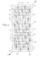
- Fig. 3 relates to a car park and shows the rational arrangement of thirty-three modules 2a, 2b in an area of about 1800 m 2 (24 m x 75 m).
- the structure provides more than 600 parking places by using five-storey modules, which require an excavation about 11 m deep in case of underground installation.
- Modules 2a, 2b are arranged side by side so that in each first module 2a three consecutive sides out of the twelve sides of the cross perimeter are contiguous with three sides of each adjoining module.
- Such an arrangement allows a rational exploitation of the available space and moreover allows reserving a specific level, for instance the ground level, for entering each lift 50 and leaving same through the oblique running lanes (dashed lines in Fig. 3).
- a specific level for instance the ground level
- the structure can also be built overground, without need of ramps, light coverings against bad weather being provided on top each lift 50.
- Each lift 50 in each module 2a, 2b is equipped with a rectangular platform 11 that can reach the various levels L 1 , L 2 ...L n of installation 1.
- Each box 13 may house a trolley 14 onto which the object(s) to be stored is (are) placed.
- Each trolley 14 will be moreover equipped with wheels or bearings 15 and will preferably serve a single box 13 exclusively.
- each level L 1 , L 2 ...L n of installation 1 may comprise one to four boxes 13, so as to adapt the structure to the ground shape, in case of underground installation, or to the particular aesthetic shape to be attained, in case of overground installation.
- Each storage module 2a, 2b forms an independent unit, and this makes the storage installation advantageously versatile: actually, it will be possible, by combining a convenient number of modules, to store from a small number of cars, as is required for small apartment buildings, to thousands of cars for the car parks of trading or industrial centres.
- platform 11 suitably has rectangular shape, as disclosed above, sized so as to house a single car 10.
- the invention may however be built also by using platforms with different shapes, e.g. with square plan, and suitably sized depending on the objects to be stored.
- platform 11 has a base 11a from which a set of uprights 11b projects upwards. Uprights 11b are arranged to support a plane 11c having hollow rails 16 intended to guide wheels 15 of trolleys 14 while the latter are being loaded onto and unloaded from platform 11.
- Wheels 15 of trolleys 14 are oriented depending on the mutually perpendicular directions along which trolleys 14 can be moved from and towards platform 11 and are arranged in parallel rows so as to correspond with hollow rails 16 provided on platform 11.
- Corresponding rails are also provided in boxes 13 to guide trolleys 14 and keep wheels 15 thereof in alignment with respect to the rails of platform 11.
- Rails 16 on platform 11 are oriented according to two perpendicular directions to allow displacing any trolley 14 both longitudinally and transversally relative to platform 11.
- the trolley translating means allowing loading and unloading trolleys 14 onto and from platform 11, are located between plane 11c and base 11a of platform 11.
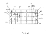
- Such means for translating trolleys 14 comprise chains or belts 30a, 30b, which are arranged along mutually perpendicular axes parallel to the sides of platform 11 and which cooperate with pairs of sprocket wheels or ring gears or pulleys 31, driven by motors (not shown) also located in the base of platform 11.
- At least six chains 30a, 30b are provided, arranged in an H-shaped pattern.
- Four chains 30a are arranged near to the minor sides of platform 11 and parallel thereto, whereas two other chains 30b are arranged perpendicularly to the first ones along the central platform line, as shown in Fig. 4.
- Chains 30a, 30b are further provided with a set of engagement members 40 arranged to be coupled with trolleys 14 to move them from platform 11 to boxes 13 and vice versa.
- Members 40 project from platform plane 11c through corresponding slots 17 formed in plane 11c.
- chains 30a, 30b and corresponding slots 17 have such a length and such an arrangement that they do not mutually interfere.
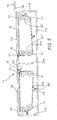
- Sprocket wheels 31, with which chains 30a, 30b mesh, are arranged in pairs on oscillating arms 32', 32".
- Arms 32' may be rotated by known means, such as a pneumatic or hydraulic cylinder (not shown), towards the outside of platform 11, while arms 32" follow the movements of arms 32' and are resiliently retained by a device acting as a tightener.
- each chain 30a, 30b may take two positions: a first position, or idle position, in which each chain 30a, 30b lies within the perimeter of platform 11 thereby allowing vertical displacement of the platform along shaft 12, ad a second position, or operating position, in which a portion of each chain 30a, 30b projects beyond the edge of platform 11 and engages, through one of members 40, trolley 14 inside the corresponding box 13.
- the H-shaped pattern with six chains 30a, 30b allows having two chains 30a projecting from each major side of platform 11 and one chain 30b projecting from each minor side of the platform.
- each chain 30a, 30b projects from platform 11 and member 40 is in suitable position for being coupled with trolley 14, arm 32' is braked so that corresponding chain 30a, 30b can safely translate trolley 14.
- Three engagement members 40 are preferably provided and are so configured that they successively enter corresponding seats 19 formed in the lower surface of trolley 14, whereby the trolleys are displaced from and onto platform 11 depending on the direction of rotation of the corresponding chain.
- Trolley 14 is locked onto platform 11 by stopping means (not shown), e.g. a brake/clamp, projecting from platform 11 itself. Once trolley 14 has been locked, arms 32" are released and arms 32' are brought back to the idle position. Platform 11 can therefore displace along shaft 12 and bring trolley 14 to the level for loading/unloading the objects to be stored. After having received a new load, platform 11 is displaced as far as it attains the level corresponding to the starting box. The same trolley 14, with its load, is placed again into the box by engagement members 40 thanks to the rotation of the chain, after trolley 14 has been released from the stopping means and after oscillating arms 32', 32" have been rotated towards the outside of platform 11.
- stopping means e.g. a brake/clamp
- Platform 11 will be displaced along shaft 12 depending on the needs, that is it will be moved to take an empty trolley from a corresponding box 13 to start the loading operation, or to take a loaded trolley for unloading the stored object(s).
- each engagement member 40 comprises a roller 41, preferably made of a non-rigid material, supported by a pair of double forks 42.
- Said double forks 42 are secured at one end, through pins 46, to a corresponding chain 30a, 30b, at two suitably spaced links 33 of said chain 30a, 30b.
- said forks 42 are moreover pivotally connected in correspondence of said roller 41 through a pivot pin 44, about which said roller 41 is rotatable.
- Pins 46 slide (with or without the help of coaxial bearings or bushes) within guides 47 located at both sides of each chain 30a, 30b and secured below plane 11c, along slots 17, so as to stabilise double forks 42 during movement of chain 30a, 30b when engagement members 40 are engaged in seats 19.
- Each double fork 42 is made of two brackets 43 shaped so as to define, when contacting each other, a seat for roller 41, a rectilinear portion passing through slot 17 and a seat for link 33 of chain 30a, 30b.
- brackets 43 are soldered along contacting sections 43a.
- engagement members 40 have been disclosed with reference to the preferred embodiment, engagement members of different shape can be manufactured, provided they suitably project so as to engage suitable seats or projections, e.g. in the shape of a tooth or a baffle, provided in trolleys 14.
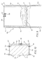
- lifting device or lift 50 for vertically moving platform 11 along shaft 12 is disclosed.
- Said lift 50 comprises four chains 51 fastened to the corners of platform 11 and turning about corresponding sprocket wheels 52 secured to two shafts 55 located on top the lift, which shafts are mutually parallel and adjacent to the minor sides of platform 11.
- a motor 58 is provided to rotate shafts 55, and hence to allow up and down movements of platform 11 of lift 50.
- the motor drives shafts 55 through a driving gear 59, a secondary shaft 56 and a pair of worm reducers 57.
- Each chain 51 is further provided at its free end with a counterweight 53 that is slidable in a proper seat 54 provided beside shaft 12 of lift 50.
- the counterweights slide in tubular members with square or rectangular cross section, which are located at the corners of shaft 12 and serve moreover as structural members of the module.
- Said advantageous mechanical solution is compatible also with using four cables, in place of the four chains, each cable having one end anchored to a platform corner and the other end anchored to a corresponding drum, provided with a helical groove, in a winch replacing each sprocket wheel.
- This arrangement requires no counterweights.
- balustrade that is lowered down to the floor level when the platform is about to move.
- Said balustrade will advantageously comprise a suitably supported and driven rectangular frame along the shaft perimeter, which frame has fastened thereto chains anchored to the floor, slightly below the plane of site. Said chains, which preferably mutually cross, can easily become extended while the frame is being lifted and be gathered below the frame when the latter is being lowered, without need for suitable and cumbersome guiding means.
- Use of metal chains allows also a high voltage electrifying, suitable to keep off animals.
- Electronic and electromechanical devices are also provided for automatically lifting lift 50, for the proper positioning thereof at the various levels and for actuating the translation of trolleys 14.
Landscapes
- Engineering & Computer Science (AREA)
- Architecture (AREA)
- Mechanical Engineering (AREA)
- Civil Engineering (AREA)
- Structural Engineering (AREA)
- Warehouses Or Storage Devices (AREA)
- Vending Machines For Individual Products (AREA)
- Liquid Crystal (AREA)
- Vehicle Body Suspensions (AREA)
- Electrochromic Elements, Electrophoresis, Or Variable Reflection Or Absorption Elements (AREA)
- Window Of Vehicle (AREA)
- Water Treatment By Sorption (AREA)
- Soundproofing, Sound Blocking, And Sound Damping (AREA)
- Iron Core Of Rotating Electric Machines (AREA)
Claims (21)
- Installation d'entreposage comprenant au moins une installation ou un module de base (2a, 2b), chaque installation ou chaque module de base (2a, 2b) comportant:un élévateur (50) doté d'une plate-forme quadrangulaire (11) et de moyens (51-59) servant à élever et à descendre ladite plate-forme (11) le long d'un arbre vertical (12) de façon que ladite plate-forme (11) soit construite pour prendre plusieurs positions correspondant à différents niveaux (L1, L2 ... Ln) le long dudit arbre (12) ;une pluralité de box (13) placés au niveau de chacun desdits différents niveaux (L1, L2 ... Ln) et disposés autour de l'arbre (12) de l'élévateur (50), un côté de chaque box (13) étant adjacent à un côté correspondant de l'arbre (12), chaque box (13) étant disposé pour loger un chariot (14) sur lequel l'objet (les objets) à stocker est (sont) placé(s) ; chaque chariot (14) étant directement translaté de son box (13) à la plate-forme (11) et vice-versa selon une direction perpendiculaire à la ligne de contiguïté entre ledit box (13) et l'arbre (12), et ladite plate-forme (11) étant pourvue de moyens de translation de chariot et de guides mutuellement perpendiculaires (16) pour gouverner les chariots (14) qui se déplacent de, ou vers, l'un quelconque des côtés de la plate-forme (11), lesdits chariots (14) étant pourvus de roues ou de supports (15) coopérant avec lesdits guides (16), lesdites roues ou lesdits supports (15) étant orienté(e)s en fonction des directions respectives, mutuellement perpendiculaires, le long desquelles lesdits chariots (14) peuvent se déplacer à partir de, et vers, ladite plate-forme (11) et étant agencés en rangées parallèles de façon à correspondre aux dits guides (16) fournis sur ladite plate-forme (11), chacun desdits box étant pourvu de son propre chariot correspondant (14) desservant exclusivement un seul box (13), caractérisée en ce que pour entrer sur lesdits chariots (14) et quitter ceux-ci, les chariots (14) dans ledit élévateur (50) sont prélevés par la plate-forme à un niveau réservé auquel ledit (lesdits) objet(s) peut (peuvent) entrer sur, ou quitter, lesdits chariots (14) tandis que lesdits chariots (14) restent sur ladite plate-forme (11).
- Installation selon la revendication 1, dans laquelle ladite plate-forme (11) et lesdits box (13) présentent un plan carré ou rectangulaire, et quatre desdits box (13) sont disposés autour de l'arbre (12) à chaque niveau de façon à définir une installation ou un module de base (2a, 2b) avec un plan configuré en croix.
- Installation selon la revendication 1 dans laquelle ladite plate-forme (11) et lesdits box (13) présentent un plan carré ou rectangulaire, et trois desdits box (13) sont disposés autour de l'arbre (12) à chaque niveau de façon à définir une installation ou un module de base (2a, 2b) avec un plan configuré en T.
- Installation selon les revendications 2 et/ou 3, comprenant une pluralité d'installations ou de modules de base (2a, 2b) avec un plan configuré en croix (2a) et/ou un plan configuré en T (2b), chaque module (2a, 2b) comportant un élévateur correspondant (50) avec des box associés (13), lesdits modules (2a, 2b) étant disposés l'un à côté de l'autre de sorte que chaque module présente trois côtés consécutifs de son périmètre adjacents aux trois côtés de chaque module adjacent (2a, 2b).
- Installation selon la revendication 4 dans laquelle ladite installation ou lesdits modules de base (2a, 2b) sont agencés côte à côte de sorte que dans chaque module trois côtés consécutifs soient contigus à trois côtés de chaque module adjacent, de sorte que pour entrer dans chaque élévateur (50) et pour quitter celui-ci, ledit (lesdits) objet(s) puisse(nt) entrer sur , ou quitter, lesdits chariots (14) audit niveau réservé par des voies de circulation obliques déterminées par ledit agencement.
- Installation selon l'une quelconque des revendications précédentes dans lequel ledit niveau réservé auquel ledit (lesdits) objet(s) peut (peuvent) entrer sur, ou quitter, lesdits chariots (14) correspond essentiellement au niveau du sol.
- Installation selon l'une quelconque des revendications précédentes dans laquelle chacune desdites installations ou desdits modules de base est autonome et permet une isolation mutuelle complète de celui-ci de sorte que des dommages causés par le feu ou par des explosions concernant un ou plusieurs module(s) peuvent être considérablement réduits.
- Installation selon l'une quelconque des revendications précédentes dans laquelle lesdits guides (16) sont obtenus par des rails creux.
- Installation selon la revendication 1 dans laquelle lesdits chariots (14) sont dotés de roues ou de supports (15) coopérant avec lesdits guides mutuellement perpendiculaires (16), lesdites roues (15) sur lesquelles les chariots (14) se déplacent étant orientées le long de deux directions respectives que les chariots (14) doivent suivre pendant une translation à partir de la plate-forme (11) vers un box adjacent (13) et vice versa, et lesdits guides (16) étant de préférence des rails creux.
- Installation selon la revendication 1 dans laquelle la plate-forme (11) de chaque élévateur (50) est pourvue de premiers moyens pour déplacer les chariots (14) dans les directions est-ouest et ouest-est et de seconds moyens pour déplacer les chariots (14) dans les directions nord-sud et sud-nord, lesdits moyens comprenant au moins une chaîne ou une courroie en boucle fermée (30a, 30b) supportée et entraînée par des pignons à chaîne ou des poulies appropriées (31), et ladite chaîne ou courroie en boucle fermée (30a, 30b) comportant au moins une dent ou un autre élément d'engagement (40) agencé pour être couplé avec le chariot (14) à déplacer, lesdits moyens de déplacement étant capables de prendre une première position, ou une position de repos , dans laquelle ladite chaîne (30a, 30b) repose à l'intérieur du périmètre de la plate-forme (11), et une seconde position, ou position de fonctionnement, dans laquelle une partie de ladite chaîne (30a, 30b) s'avance au-delà du bord de la plate-forme (11) de sorte que ledit élément d'engagement (40) puisse engager une embase correspondante (19) présente dans lesdits chariots (14), permettant de ce fait un déplacement des chariots (14) à partir de et vers la plate-forme (11).
- Installation selon la revendication 10 dans laquelle lesdits pignons à chaîne ou lesdites poulies (31) sont montés sur des bras oscillants (32', 32") connectés à pivotement à la plate-forme (11) de sorte qu'ils entraînent lesdits moyens de déplacement à prendre lesdites première et seconde positions.
- Installation selon la revendication 10 dans laquelle le nombre desdits éléments d'engagement (40) pour chaque chaîne ou courroie (30a, 30b) est tel que, pendant la rotation de la chaîne ou de la courroie (30a, 30b), la translation complète des chariots (14) desdits box (13) vers ladite plate-forme (11) et vice-versa est possible.
- Installation selon la revendication 10 dans laquelle chaque dit moyen de déplacement comporte au moins deux paires de pignons à chaîne ou de poulies (31), chaque paire de pignons à chaîne ou de poulies (31) comprenant un premier pignon à chaîne ou une première poulie (31) monté(e) à pivotement sur l'axe sur lequel le bras oscillant correspondant (32', 32") est monté à pivotement, et un second pignon à chaîne ou une seconde poulie (31) monté(e) à vide à l'extrémité opposée dudit bras oscillant (32', 32") de sorte qu'un système de parallélogramme déformable est obtenu qui peut être déformé, à cause de la demi rotation des bras oscillants (32', 32"), pour permettre à l'un desdits seconds pignon à chaîne ou à l'une desdites secondes poulies (31) qui repose à l'extérieur de la plate-forme (11) d'être placé(e) au-dessous du chariot (14).
- Installation selon la revendication 13 dans laquelle chaque bras oscillant (32') monté à pivotement près du bord extérieur de la plate-forme (11) est muni de moyens d'entraînement commandant son oscillation, et dans laquelle chaque bras oscillant (32") monté à pivotement dans une position presque centrale est muni de moyens de tendeurs élastiques qui maintiennent tendue ladite chaîne ou ladite courroie (30a, 30b), et d'un frein, lequel bloque le bras dès que la chaîne ou la courroie (30a, 30b) doit exercer une action de traction pour translater le chariot (14) à partir de, ou vers, la plate-forme (11).
- Installation selon la revendication 10 dans laquelle les éléments d'engagement (40) destinés à un couplage avec les chariots (14) comportent une paire de fourches doubles (42) fixées aux chaînes ou aux courroies (30a, 30b), lesdites doubles fourches (42) étant articulées mutuellement et étant connectées à pivotement aux chaînes ou aux courroies (30a, 30b) par des broches (45) de façon à déterminer une configuration triangulaire de l'élément d'engagement (40) et à permettre sa déformation le long de chemins curvilignes.
- Installation selon la revendication 15 dans laquelle les broches (45) par lesquelles les doubles fourches (42) sont connectées à pivotement aux chaînes ou aux courroies (30a, 30b) s'avancent transversalement à partir desdites chaînes ou desdites courroies (30a, 30b) de façon à pouvoir coulisser, avec ou sans supports ou boîtes de glissement interposés, à l'intérieur des guides longitudinaux appropriés (47) assurant la stabilité de l'élément d'engagement (40) lorsqu'il se trouve sous contrainte pendant la translation des chariots (14).
- Installation selon la revendication 1 dans laquelle pour déplacer la plate-forme (11) de l'élévateur (50), quatre chaînes ouvertes (51) sont prévues, chacune ayant une extrémité étant fixée à l'un des coins de la plate-forme (11) et l'autre extrémité étant fixée à un contrepoids correspondant (53), chaque chaîne (51) étant supportée au sommet par un pignon à chaîne correspondant (52) monté sur un arbre entraîné par moteur.
- Installation selon la revendication 17 dans laquelle deux arbres parallèles entraînés par moteur (55) agencés au sommet dudit arbre (12) sont prévus, chacun desdits arbres entraînés par moteur (55) supportant deux desdits pignons à chaîne (52), et dans laquelle un réducteur de vis sans fin (57) est fourni pour chaque dit arbre (15), lesdits réducteurs (57) étant commandés par un seul moteur (58) à travers un pignon d'entraînement (59) et un arbre secondaire (46).
- Installation selon la revendication 17 comprenant des guides verticaux (54) constitués, de préférence, d'éléments tubulaires ayant une section transversale carrée ou rectangulaire, lesdits guides (54) étant des éléments structuraux de l'arbre (12) de l'élévateur (50) et étant agencés de façon à ce qu'ils permettent aux dits contrepoids (53) de coulisser à l'intérieur de ceux-ci.
- Installation selon la revendication 1 dans laquelle les déplacements de la plate-forme (11) sont obtenus par des câbles chacun étant ancré au niveau d' une extrémité inférieure à un angle correspondant de la plate-forme et au niveau de l'extrémité supérieure à un tambour de rotation correspondant d'un treuil.
- Installation selon la revendication 1 dans laquelle chaque arbre (12) est entouré d'une balustrade verticalement mobile comprenant un bâti disposé le long du périmètre de l'arbre, lequel bâti présente, fixées à lui, des chaînes ancrées au sol, légèrement au-dessous du plan de site, à une étendue telle qu'elles puissent être rassemblées au-dessous dudit plan de site lorsque le bâti se trouve verticalement descendu au niveau du plancher.
Applications Claiming Priority (3)
| Application Number | Priority Date | Filing Date | Title |
|---|---|---|---|
| SM200200008 | 2002-04-22 | ||
| SM200200008A SM200200008B (it) | 2002-04-22 | 2002-04-22 | Impianto di magazzinaggio |
| PCT/IB2003/001402 WO2003089737A1 (fr) | 2002-04-22 | 2003-04-15 | Installation d'entreposage |
Publications (2)
| Publication Number | Publication Date |
|---|---|
| EP1497516A1 EP1497516A1 (fr) | 2005-01-19 |
| EP1497516B1 true EP1497516B1 (fr) | 2006-11-15 |
Family
ID=29247068
Family Applications (1)
| Application Number | Title | Priority Date | Filing Date |
|---|---|---|---|
| EP03712526A Expired - Lifetime EP1497516B1 (fr) | 2002-04-22 | 2003-04-15 | Installation d'entreposage |
Country Status (9)
| Country | Link |
|---|---|
| EP (1) | EP1497516B1 (fr) |
| CN (1) | CN1300432C (fr) |
| AT (1) | ATE345429T1 (fr) |
| AU (1) | AU2003216616A1 (fr) |
| DE (1) | DE60309688T2 (fr) |
| ES (1) | ES2276051T3 (fr) |
| RU (1) | RU2311518C2 (fr) |
| SM (1) | SM200200008B (fr) |
| WO (1) | WO2003089737A1 (fr) |
Cited By (1)
| Publication number | Priority date | Publication date | Assignee | Title |
|---|---|---|---|---|
| CN100587210C (zh) * | 2007-10-15 | 2010-02-03 | 裘苗全 | 墨水瓶式的立体自动停车库 |
Families Citing this family (5)
| Publication number | Priority date | Publication date | Assignee | Title |
|---|---|---|---|---|
| NL2004264C2 (nl) * | 2010-02-18 | 2011-08-22 | Kaak Johan H B | Inrichting voor het tijdelijk opnemen van producthouders en samenstel voor deegverwerking omvattende een dergelijke inrichting. |
| CN103132754B (zh) * | 2011-11-30 | 2015-11-25 | 北京鑫华源机械制造有限责任公司 | 新型高层停车设备 |
| CN103590639B (zh) * | 2013-11-18 | 2016-03-30 | 四川兴事发新型建材有限公司 | 模块化升降横移式的停车设备 |
| CN106639432A (zh) * | 2016-02-05 | 2017-05-10 | 唐恩泽 | 一种用于车辆升降的载车厢 |
| JP6898805B2 (ja) * | 2017-08-11 | 2021-07-07 | 日精株式会社 | フォーク式機械駐車装置 |
Family Cites Families (6)
| Publication number | Priority date | Publication date | Assignee | Title |
|---|---|---|---|---|
| US3616945A (en) * | 1968-10-16 | 1971-11-02 | Nils A S Gynne | Construction for storage of cars |
| JPS6198708U (fr) * | 1984-12-03 | 1986-06-24 | ||
| US5069592A (en) * | 1990-03-13 | 1991-12-03 | Lev Galperin | Automated multistorey parking building |
| US5118239A (en) * | 1990-05-23 | 1992-06-02 | Nissei Build Kogyo Kabushiki Kaisha | Cubic parking apparatus |
| RU2120012C1 (ru) * | 1997-08-04 | 1998-10-10 | Олег Константинович Егоров | Многоярусная механизированная автостоянка |
| IT1310793B1 (it) * | 1999-12-02 | 2002-02-22 | Pineta Srl | Carrello per movimentare autoveicoli in un parcheggio |
-
2002
- 2002-04-22 SM SM200200008A patent/SM200200008B/it unknown
-
2003
- 2003-04-15 EP EP03712526A patent/EP1497516B1/fr not_active Expired - Lifetime
- 2003-04-15 RU RU2004133890/03A patent/RU2311518C2/ru not_active IP Right Cessation
- 2003-04-15 CN CNB038091011A patent/CN1300432C/zh not_active Expired - Fee Related
- 2003-04-15 WO PCT/IB2003/001402 patent/WO2003089737A1/fr not_active Ceased
- 2003-04-15 AT AT03712526T patent/ATE345429T1/de not_active IP Right Cessation
- 2003-04-15 DE DE60309688T patent/DE60309688T2/de not_active Expired - Lifetime
- 2003-04-15 AU AU2003216616A patent/AU2003216616A1/en not_active Abandoned
- 2003-04-15 ES ES03712526T patent/ES2276051T3/es not_active Expired - Lifetime
Cited By (1)
| Publication number | Priority date | Publication date | Assignee | Title |
|---|---|---|---|---|
| CN100587210C (zh) * | 2007-10-15 | 2010-02-03 | 裘苗全 | 墨水瓶式的立体自动停车库 |
Also Published As
| Publication number | Publication date |
|---|---|
| AU2003216616A1 (en) | 2003-11-03 |
| EP1497516A1 (fr) | 2005-01-19 |
| SM200200008A (it) | 2003-10-22 |
| RU2004133890A (ru) | 2005-07-10 |
| SM200200008B (it) | 2003-10-22 |
| DE60309688D1 (de) | 2006-12-28 |
| DE60309688T2 (de) | 2007-09-06 |
| CN1300432C (zh) | 2007-02-14 |
| WO2003089737A1 (fr) | 2003-10-30 |
| ATE345429T1 (de) | 2006-12-15 |
| CN1646780A (zh) | 2005-07-27 |
| ES2276051T3 (es) | 2007-06-16 |
| RU2311518C2 (ru) | 2007-11-27 |
Similar Documents
| Publication | Publication Date | Title |
|---|---|---|
| KR950002252B1 (ko) | 입체 주차장치 | |
| US3860130A (en) | Storage and retrieval system | |
| JPH094264A (ja) | 立体型駐車システム | |
| KR100466664B1 (ko) | 최대자동차주차장치 | |
| KR910004795B1 (ko) | 자체 입고수단을 갖는 입체형 주차장치 | |
| WO1987002405A1 (fr) | Appareil de stockage vertical et procede de commande | |
| EP0386170B1 (fr) | Parking multi-etage | |
| US4594044A (en) | Rotating truck lift | |
| EP1497516B1 (fr) | Installation d'entreposage | |
| EP0544990B1 (fr) | Installation de stockage à étages et colonnes multiples | |
| CN215107763U (zh) | 一种适用于圆形场地的平面移动类梳齿式停车设备 | |
| CZ20031063A3 (cs) | Zařízení na skladování předmětů v otočných patrových mezikružích | |
| SU1650893A1 (ru) | Автоматизированный гараж | |
| RU68043U1 (ru) | Многоместный механизированный гараж | |
| JP2577647B2 (ja) | 立体機械式駐車設備 | |
| KR0120833Y1 (ko) | 입체형 주차장치의 팔레트 승강구조 | |
| SU1636548A1 (ru) | Устройство дл обслуживани кровли теплицы | |
| KR910004793B1 (ko) | 다단식 주차장의 차량이송장치 | |
| RU51067U1 (ru) | Гараж механизированный | |
| JPH03208970A (ja) | 立体駐車装置 | |
| JPS6339328Y2 (fr) | ||
| JP2551340Y2 (ja) | 機械式駐車設備 | |
| KR900000797Y1 (ko) | 입체 주차장의 구동장치 | |
| JPS6324204Y2 (fr) | ||
| RU49068U1 (ru) | Гараж механизированный |
Legal Events
| Date | Code | Title | Description |
|---|---|---|---|
| PUAI | Public reference made under article 153(3) epc to a published international application that has entered the european phase |
Free format text: ORIGINAL CODE: 0009012 |
|
| 17P | Request for examination filed |
Effective date: 20041006 |
|
| AK | Designated contracting states |
Kind code of ref document: A1 Designated state(s): AT BE BG CH CY CZ DE DK EE ES FI FR GB GR HU IE IT LI LU MC NL PT RO SE SI SK TR |
|
| AX | Request for extension of the european patent |
Extension state: AL LT LV MK |
|
| GRAP | Despatch of communication of intention to grant a patent |
Free format text: ORIGINAL CODE: EPIDOSNIGR1 |
|
| GRAS | Grant fee paid |
Free format text: ORIGINAL CODE: EPIDOSNIGR3 |
|
| GRAA | (expected) grant |
Free format text: ORIGINAL CODE: 0009210 |
|
| AK | Designated contracting states |
Kind code of ref document: B1 Designated state(s): AT BE BG CH CY CZ DE DK EE ES FI FR GB GR HU IE IT LI LU MC NL PT RO SE SI SK TR |
|
| PG25 | Lapsed in a contracting state [announced via postgrant information from national office to epo] |
Ref country code: RO Free format text: LAPSE BECAUSE OF FAILURE TO SUBMIT A TRANSLATION OF THE DESCRIPTION OR TO PAY THE FEE WITHIN THE PRESCRIBED TIME-LIMIT Effective date: 20061115 Ref country code: CZ Free format text: LAPSE BECAUSE OF FAILURE TO SUBMIT A TRANSLATION OF THE DESCRIPTION OR TO PAY THE FEE WITHIN THE PRESCRIBED TIME-LIMIT Effective date: 20061115 Ref country code: CH Free format text: LAPSE BECAUSE OF FAILURE TO SUBMIT A TRANSLATION OF THE DESCRIPTION OR TO PAY THE FEE WITHIN THE PRESCRIBED TIME-LIMIT Effective date: 20061115 Ref country code: AT Free format text: LAPSE BECAUSE OF FAILURE TO SUBMIT A TRANSLATION OF THE DESCRIPTION OR TO PAY THE FEE WITHIN THE PRESCRIBED TIME-LIMIT Effective date: 20061115 Ref country code: NL Free format text: LAPSE BECAUSE OF FAILURE TO SUBMIT A TRANSLATION OF THE DESCRIPTION OR TO PAY THE FEE WITHIN THE PRESCRIBED TIME-LIMIT Effective date: 20061115 Ref country code: SK Free format text: LAPSE BECAUSE OF FAILURE TO SUBMIT A TRANSLATION OF THE DESCRIPTION OR TO PAY THE FEE WITHIN THE PRESCRIBED TIME-LIMIT Effective date: 20061115 Ref country code: BE Free format text: LAPSE BECAUSE OF FAILURE TO SUBMIT A TRANSLATION OF THE DESCRIPTION OR TO PAY THE FEE WITHIN THE PRESCRIBED TIME-LIMIT Effective date: 20061115 Ref country code: SI Free format text: LAPSE BECAUSE OF FAILURE TO SUBMIT A TRANSLATION OF THE DESCRIPTION OR TO PAY THE FEE WITHIN THE PRESCRIBED TIME-LIMIT Effective date: 20061115 Ref country code: LI Free format text: LAPSE BECAUSE OF FAILURE TO SUBMIT A TRANSLATION OF THE DESCRIPTION OR TO PAY THE FEE WITHIN THE PRESCRIBED TIME-LIMIT Effective date: 20061115 Ref country code: FI Free format text: LAPSE BECAUSE OF FAILURE TO SUBMIT A TRANSLATION OF THE DESCRIPTION OR TO PAY THE FEE WITHIN THE PRESCRIBED TIME-LIMIT Effective date: 20061115 |
|
| REG | Reference to a national code |
Ref country code: GB Ref legal event code: FG4D |
|
| REG | Reference to a national code |
Ref country code: CH Ref legal event code: EP |
|
| REF | Corresponds to: |
Ref document number: 60309688 Country of ref document: DE Date of ref document: 20061228 Kind code of ref document: P |
|
| REG | Reference to a national code |
Ref country code: IE Ref legal event code: FG4D |
|
| PG25 | Lapsed in a contracting state [announced via postgrant information from national office to epo] |
Ref country code: DK Free format text: LAPSE BECAUSE OF FAILURE TO SUBMIT A TRANSLATION OF THE DESCRIPTION OR TO PAY THE FEE WITHIN THE PRESCRIBED TIME-LIMIT Effective date: 20070215 Ref country code: SE Free format text: LAPSE BECAUSE OF FAILURE TO SUBMIT A TRANSLATION OF THE DESCRIPTION OR TO PAY THE FEE WITHIN THE PRESCRIBED TIME-LIMIT Effective date: 20070215 Ref country code: BG Free format text: LAPSE BECAUSE OF FAILURE TO SUBMIT A TRANSLATION OF THE DESCRIPTION OR TO PAY THE FEE WITHIN THE PRESCRIBED TIME-LIMIT Effective date: 20070215 |
|
| PG25 | Lapsed in a contracting state [announced via postgrant information from national office to epo] |
Ref country code: PT Free format text: LAPSE BECAUSE OF FAILURE TO SUBMIT A TRANSLATION OF THE DESCRIPTION OR TO PAY THE FEE WITHIN THE PRESCRIBED TIME-LIMIT Effective date: 20070416 |
|
| NLV1 | Nl: lapsed or annulled due to failure to fulfill the requirements of art. 29p and 29m of the patents act | ||
| REG | Reference to a national code |
Ref country code: CH Ref legal event code: PL |
|
| ET | Fr: translation filed | ||
| REG | Reference to a national code |
Ref country code: ES Ref legal event code: FG2A Ref document number: 2276051 Country of ref document: ES Kind code of ref document: T3 |
|
| PLBE | No opposition filed within time limit |
Free format text: ORIGINAL CODE: 0009261 |
|
| STAA | Information on the status of an ep patent application or granted ep patent |
Free format text: STATUS: NO OPPOSITION FILED WITHIN TIME LIMIT |
|
| 26N | No opposition filed |
Effective date: 20070817 |
|
| PG25 | Lapsed in a contracting state [announced via postgrant information from national office to epo] |
Ref country code: GR Free format text: LAPSE BECAUSE OF FAILURE TO SUBMIT A TRANSLATION OF THE DESCRIPTION OR TO PAY THE FEE WITHIN THE PRESCRIBED TIME-LIMIT Effective date: 20070216 |
|
| PG25 | Lapsed in a contracting state [announced via postgrant information from national office to epo] |
Ref country code: IE Free format text: LAPSE BECAUSE OF NON-PAYMENT OF DUE FEES Effective date: 20070416 |
|
| PG25 | Lapsed in a contracting state [announced via postgrant information from national office to epo] |
Ref country code: EE Free format text: LAPSE BECAUSE OF FAILURE TO SUBMIT A TRANSLATION OF THE DESCRIPTION OR TO PAY THE FEE WITHIN THE PRESCRIBED TIME-LIMIT Effective date: 20061115 |
|
| PG25 | Lapsed in a contracting state [announced via postgrant information from national office to epo] |
Ref country code: MC Free format text: LAPSE BECAUSE OF NON-PAYMENT OF DUE FEES Effective date: 20070430 |
|
| PG25 | Lapsed in a contracting state [announced via postgrant information from national office to epo] |
Ref country code: CY Free format text: LAPSE BECAUSE OF FAILURE TO SUBMIT A TRANSLATION OF THE DESCRIPTION OR TO PAY THE FEE WITHIN THE PRESCRIBED TIME-LIMIT Effective date: 20061115 Ref country code: LU Free format text: LAPSE BECAUSE OF NON-PAYMENT OF DUE FEES Effective date: 20070415 |
|
| PG25 | Lapsed in a contracting state [announced via postgrant information from national office to epo] |
Ref country code: TR Free format text: LAPSE BECAUSE OF FAILURE TO SUBMIT A TRANSLATION OF THE DESCRIPTION OR TO PAY THE FEE WITHIN THE PRESCRIBED TIME-LIMIT Effective date: 20061115 Ref country code: HU Free format text: LAPSE BECAUSE OF FAILURE TO SUBMIT A TRANSLATION OF THE DESCRIPTION OR TO PAY THE FEE WITHIN THE PRESCRIBED TIME-LIMIT Effective date: 20070516 |
|
| PG25 | Lapsed in a contracting state [announced via postgrant information from national office to epo] |
Ref country code: IT Free format text: LAPSE BECAUSE OF NON-PAYMENT OF DUE FEES Effective date: 20100415 |
|
| PGRI | Patent reinstated in contracting state [announced from national office to epo] |
Ref country code: IT Effective date: 20110616 |
|
| REG | Reference to a national code |
Ref country code: FR Ref legal event code: PLFP Year of fee payment: 13 |
|
| PGFP | Annual fee paid to national office [announced via postgrant information from national office to epo] |
Ref country code: GB Payment date: 20150331 Year of fee payment: 13 |
|
| PGFP | Annual fee paid to national office [announced via postgrant information from national office to epo] |
Ref country code: DE Payment date: 20150331 Year of fee payment: 13 Ref country code: ES Payment date: 20150407 Year of fee payment: 13 |
|
| PGFP | Annual fee paid to national office [announced via postgrant information from national office to epo] |
Ref country code: FR Payment date: 20150417 Year of fee payment: 13 Ref country code: IT Payment date: 20150417 Year of fee payment: 13 |
|
| REG | Reference to a national code |
Ref country code: DE Ref legal event code: R119 Ref document number: 60309688 Country of ref document: DE |
|
| GBPC | Gb: european patent ceased through non-payment of renewal fee |
Effective date: 20160415 |
|
| REG | Reference to a national code |
Ref country code: FR Ref legal event code: ST Effective date: 20161230 |
|
| PG25 | Lapsed in a contracting state [announced via postgrant information from national office to epo] |
Ref country code: FR Free format text: LAPSE BECAUSE OF NON-PAYMENT OF DUE FEES Effective date: 20160502 Ref country code: GB Free format text: LAPSE BECAUSE OF NON-PAYMENT OF DUE FEES Effective date: 20160415 Ref country code: DE Free format text: LAPSE BECAUSE OF NON-PAYMENT OF DUE FEES Effective date: 20161101 |
|
| PG25 | Lapsed in a contracting state [announced via postgrant information from national office to epo] |
Ref country code: IT Free format text: LAPSE BECAUSE OF NON-PAYMENT OF DUE FEES Effective date: 20160415 |
|
| PG25 | Lapsed in a contracting state [announced via postgrant information from national office to epo] |
Ref country code: ES Free format text: LAPSE BECAUSE OF NON-PAYMENT OF DUE FEES Effective date: 20160416 |
|
| REG | Reference to a national code |
Ref country code: ES Ref legal event code: FD2A Effective date: 20181204 |