EP1497536B1 - Schwingscheibenschneider mit geschwindigkeitssteuerlagern - Google Patents
Schwingscheibenschneider mit geschwindigkeitssteuerlagern Download PDFInfo
- Publication number
- EP1497536B1 EP1497536B1 EP03717030A EP03717030A EP1497536B1 EP 1497536 B1 EP1497536 B1 EP 1497536B1 EP 03717030 A EP03717030 A EP 03717030A EP 03717030 A EP03717030 A EP 03717030A EP 1497536 B1 EP1497536 B1 EP 1497536B1
- Authority
- EP
- European Patent Office
- Prior art keywords
- bearing
- cutter according
- disc cutter
- oscillating disc
- cutting
- Prior art date
- Legal status (The legal status is an assumption and is not a legal conclusion. Google has not performed a legal analysis and makes no representation as to the accuracy of the status listed.)
- Expired - Lifetime
Links
- 230000002706 hydrostatic effect Effects 0.000 claims abstract description 32
- 239000012530 fluid Substances 0.000 claims abstract description 25
- XLYOFNOQVPJJNP-UHFFFAOYSA-N water Substances O XLYOFNOQVPJJNP-UHFFFAOYSA-N 0.000 claims abstract description 17
- 230000000694 effects Effects 0.000 claims abstract description 4
- 230000010355 oscillation Effects 0.000 claims abstract description 3
- 230000001939 inductive effect Effects 0.000 claims description 2
- 239000003921 oil Substances 0.000 description 24
- 239000011435 rock Substances 0.000 description 7
- 230000001276 controlling effect Effects 0.000 description 3
- 238000001816 cooling Methods 0.000 description 2
- 230000001105 regulatory effect Effects 0.000 description 2
- 230000001133 acceleration Effects 0.000 description 1
- 239000003831 antifriction material Substances 0.000 description 1
- 239000000498 cooling water Substances 0.000 description 1
- 238000006073 displacement reaction Methods 0.000 description 1
- 230000002708 enhancing effect Effects 0.000 description 1
- 230000006698 induction Effects 0.000 description 1
- 238000012423 maintenance Methods 0.000 description 1
- 210000002445 nipple Anatomy 0.000 description 1
- 230000002093 peripheral effect Effects 0.000 description 1
- 238000009987 spinning Methods 0.000 description 1
Images


Classifications
-
- F—MECHANICAL ENGINEERING; LIGHTING; HEATING; WEAPONS; BLASTING
- F16—ENGINEERING ELEMENTS AND UNITS; GENERAL MEASURES FOR PRODUCING AND MAINTAINING EFFECTIVE FUNCTIONING OF MACHINES OR INSTALLATIONS; THERMAL INSULATION IN GENERAL
- F16C—SHAFTS; FLEXIBLE SHAFTS; ELEMENTS OR CRANKSHAFT MECHANISMS; ROTARY BODIES OTHER THAN GEARING ELEMENTS; BEARINGS
- F16C21/00—Combinations of sliding-contact bearings with ball or roller bearings, for exclusively rotary movement
-
- E—FIXED CONSTRUCTIONS
- E21—EARTH OR ROCK DRILLING; MINING
- E21C—MINING OR QUARRYING
- E21C25/00—Cutting machines, i.e. for making slits approximately parallel or perpendicular to the seam
- E21C25/16—Machines slitting solely by one or more rotating saws, cutting discs, or wheels
-
- E—FIXED CONSTRUCTIONS
- E21—EARTH OR ROCK DRILLING; MINING
- E21D—SHAFTS; TUNNELS; GALLERIES; LARGE UNDERGROUND CHAMBERS
- E21D9/00—Tunnels or galleries, with or without linings; Methods or apparatus for making thereof; Layout of tunnels or galleries
- E21D9/10—Making by using boring or cutting machines
- E21D9/1006—Making by using boring or cutting machines with rotary cutting tools
- E21D9/104—Cutting tool fixtures
- E21D9/1046—Vibrating
-
- F—MECHANICAL ENGINEERING; LIGHTING; HEATING; WEAPONS; BLASTING
- F16—ENGINEERING ELEMENTS AND UNITS; GENERAL MEASURES FOR PRODUCING AND MAINTAINING EFFECTIVE FUNCTIONING OF MACHINES OR INSTALLATIONS; THERMAL INSULATION IN GENERAL
- F16C—SHAFTS; FLEXIBLE SHAFTS; ELEMENTS OR CRANKSHAFT MECHANISMS; ROTARY BODIES OTHER THAN GEARING ELEMENTS; BEARINGS
- F16C32/00—Bearings not otherwise provided for
- F16C32/06—Bearings not otherwise provided for with moving member supported by a fluid cushion formed, at least to a large extent, otherwise than by movement of the shaft, e.g. hydrostatic air-cushion bearings
- F16C32/0681—Construction or mounting aspects of hydrostatic bearings, for exclusively rotary movement, related to the direction of load
- F16C32/0692—Construction or mounting aspects of hydrostatic bearings, for exclusively rotary movement, related to the direction of load for axial load only
Definitions
- This invention relates to an oscillating disc cutter with speed controlling bearings and has been devised particularly though not solely to prevent high speed rotation of a disc cutter when the cutting disc is disengaged from a rock face.
- Oscillating disc cutters of the type described in international patent specification PCT/ AU00/00066 have the general requirement that a mechanism is provided to prevent the cutting disc from rotating at a high speed when the cutter is not engaging the rock face.
- Such a gear arrangement is heavy, prone to wear, maintenance issues, and causes additional drag when the cutter is engaged with the rock face.
- an oscillating disc cutter including a cutting disc and a drive mechanism
- the drive mechanism including a drive shaft to effect eccentric oscillation of the cutting disc and a radial bearing disposed to permit relative rotation between the drive shaft and the cutting disc
- the cutter further including a first axial bearing disposed to react axial forces while accommodating induced rotation of the cutting disc when operatively engaged and to induce a rotational drag thereby limiting rotational speed of the cutting disc when free running.
- the cutter further includes a second bearing to induce a predetermined axial load in the first bearing.
- the second bearing substantially reacts the axial forces induced by the first bearing.
- the first bearing is a oil operated hydrostatic bearing and the second bearing is a fluid pressurised and lubricated bearing.
- pressure in the fluid bearing is maintained at a level such that a predetermined maximum running clearance in the hydrostatic bearing is maintained thereby inducing shear forces in the oil of the hydrostatic bearing.
- the shear forces cause rotational drag in the bearing thereby limiting the rotational speed of the cutting disc in when free running.
- the fluid bearing is takes the form of a water-pressurised annulus.
- the limited rotational speed of the cutting disc is 0 to 100 rpm.
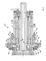
- oscillating disc cutter shown in the accompanying drawing is generally similar in configuration to that shown in Figure 7 of international patent specification PCT/AU00/00066 , with like numbers referring to the components in that drawing as described in the description of the international patent specification.
- bearing 605 in the present invention is water lubricated.
- Bearing 606 is replaced by a hydrostatic bearing 700 supplied with high pressure oil through an annular passageway 701 inside a demountable ring 702, to which oil is supplied under pressure via nipple 703.
- the bearing 700 contains pockets 800 in the normal manner of hydrostatic bearings.
- these pockets may be in the form of a concentric grid pattern on the casing body opposing the disc 603, however, in alternative embodiments they may take on any form as is known in the art of hydrostatic bearings.
- Each pocket's extremity is defined by a peripheral groove 801.
- a further oil channel groove in the form of a cross 802 dissects each pocket into four lands 803.
- these lands are at substantially the same height as the bearing surface between the pockets.
- Many hydrostatic bearings do not include these lands and the pockets are merely depressions in the bearing surface.
- the lands effectively function to reduce the clearance gap between the bearing surfaces over a greater area thereby increasing the shear in the oil and enhancing the viscous drag characteristics of the bearing.
- Oil is feed into the centre of each cross through a respective flow control orifice 706.
- Each respective orifice regulates the oil in each of the pockets of the bearing as is common in hydrostatic bearings.
- oil exiting the bearing is able to seep either directly into the body of the device between bearings 609 and 610 or into outer drain channel 705 at the periphery of the bearing.
- fluid bearing 605. This fluid bearing maybe considered simply as a pressurised annulus, however, is referred to throughout as a fluid lubricated bearing.
- the fluid bearing surfaces include an annular plate portion of the disc 603 and a corresponding portion of the cutter housing opposing the annular plate. These bearing surfaces are separated by an annular gap into which water is introduced at pressure through a series of passageways 607.
- a hose and hose fittings may be used to transport pressurised water from a pressure pump (not shown). In this embodiment the water is en-route to the cooling jets for the cutting edge of the cutter however, in other embodiments, separate cooling water and bearing water systems may be used. In still further embodiments, different fluids may be used for cooling and pressurising the fluid bearing.
- the pressurised water provides a force on the plate thereby maintaining clearance between the bearing surfaces and providing an opposing force to the hydrostatic bearing. It will be appreciated that by regulating the pressure of the water, the magnitude of opposing force may also be regulated. Accordingly, by carefully controlling the water pressure in the fluid bearing and the oil pressure in the hydrostatic bearing, the clearance between the faces of the hydrostatic bearing can be set.
- the fluid bearing allows for a minute amount of axial yaw if the cutter head is differentially loaded. Such differential loading is accommodated and resisted by the hydrostatic bearing.
- the fluid bearing surfaces may be covered with an antifriction material, as a safety measure should the bearing surfaces contact, for instance, as a result of failed water supply or during transport.
- Typical values for the oil pressure supplied to the hydrostatic bearing and water pressure supplied to the fluid bearing are 14,000 kPa and 800 kPa respectively.
- the cutter is powered by a 2-pole induction motor which, with a power supply at 50 Hz, rotates the dive shaft 612 at a speed of around 3000 rpm.
- a power supply at 50 Hz
- the dive shaft 612 rotates at a speed of around 3000 rpm.
- alternative power supplies and a range of cutting speeds may be used.
- the pressure of water supplied to the water lubricated bearing, the oil type, and the oil viscosity, temperature and pressure in the hydrostatic bearing are all carefully selected and controlled where appropriate to ensure correct function of the bearing and to avoid damage to the parts.
- the oil is passed through a heat exchanger of sufficient capacity to control the oil temperature.
- An additional retardation force may be applied by drag inherent in the fluid bearing. Disengaging the cutter from the rock face reduces the axial load on the hydrostatic bearing which in turn causes the disc 603 to be forced closer to the water lubricated bearing surface 605. This may provide for an increase in drag thereby preventing the disc 603, to which the disc cutter 602 is bolted, from rotating at a high speed when the cutter is not engaging the rock face.
- the free running speed is selected to be about 30-40 rpm. While this is in the reverse direction to the operational speed, the difference is small enough to prevent damage and substantial wear to the cutter disc.
- the parameters of the system may be selected to provide for virtually any free running speed desired in the direction of the shaft.
- axial load bearings may replace the hydrostatic and fluid lubricated bearings.
- the hydrostatic bearing may be replaced by a Michell bearing and the fluid lubricated bearing may take to form of a mechanical, hydrodynamic, electromagnetic or other type of bearing able to withstand and/or provide an axial load.
- one or other of the bearings may have a more significant effect in controlling the speed of the cutter disc when free spinning.
- the invention provides an effective means for limiting the speed of the cutter disc when in free running mode without the use of mechanical parts which are comparatively higher wearing.
- the water lubricated bearing 605 and the hydrostatic bearing function as drag brakes on the rotation of the disc 603 and hence of the cutter 602.
Landscapes
- Engineering & Computer Science (AREA)
- General Engineering & Computer Science (AREA)
- Mining & Mineral Resources (AREA)
- Mechanical Engineering (AREA)
- Life Sciences & Earth Sciences (AREA)
- General Life Sciences & Earth Sciences (AREA)
- Geochemistry & Mineralogy (AREA)
- Geology (AREA)
- Environmental & Geological Engineering (AREA)
- Magnetic Bearings And Hydrostatic Bearings (AREA)
- Automatic Control Of Machine Tools (AREA)
- Turning (AREA)
Claims (16)
- Ein Schwingscheibenschneidwerkzeug, das eine Schneidscheibe und einen Antriebsmechanismus umfasst, wobei der Antriebsmechanismus eine Antriebswelle (612) umfasst, um die exzentrische Schwingung der Schneidscheibe zu bewirken, und ein Radiallager, das angeordnet ist, um die relative Drehung zwischen der Antriebswelle (612) und der Schneidscheibe zu ermöglichen, umfasst, dadurch gekennzeichnet, dass
das Schneidewerkzeug ferner ein erstes Axiallager (700) umfasst, das angeordnet ist, um axialen Kräften entgegenzuwirken, während es die induzierte Drehung der Schneidscheibe ermöglicht, wenn sie funktionsfähig im Einsatz ist, und um einen Drehwiderstand zu induzieren, wodurch die Drehgeschwindigkeit der Schneidscheibe beschränkt wird, wenn sie frei läuft. - Schwingscheibenschneidwerkzeug gemäß Anspruch 1, das ferner ein zweites Lager (605) umfasst, um in dem ersten Lager (700) eine zuvor bestimmte axiale Belastung zu induzieren.
- Schwingscheibenschneidwerkzeug gemäß Anspruch 2, wobei das zweite Lager (605) im Wesentlichen den axialen Kräften entgegenwirkt, die von dem ersten Lager (700) induziert werden.
- Schwingscheibenschneidwerkzeug gemäß Anspruch 2 oder 3, wobei das erste Lager (700) eine relativ hohe Reibung zeigt
und das zweite Lager (605) eine relativ geringere Reibung zeigt. - Schwingscheibenschneidwerkzeug gemäß einem der Ansprüche 2 bis 4, wobei das erste Lager (700) ein hydrostatisches Lager (700) ist.
- Schwingscheibenschneidwerkzeug gemäß einem der Ansprüche 2 bis 5, wobei das zweite Lager (605) ein fluidgeschmiertes Lager ist.
- Schwingscheibenschneidwerkzeug gemäß Anspruch 5 oder 6, wobei das hydrostatische Lager (700) den axialen Schneidkräften im funktionsfähigen Schneidmodus im Wesentlichen entgegenwirkt.
- Schwingscheibenschneidwerkzeug gemäß Anspruch 7, wobei das hydrostatische Lager (700) mit Öl betrieben wird.
- Schwingscheibenschneidwerkzeug gemäß Anspruch 8, wobei das Fluidlager (605) unter Druck gesetzt wird.
- Schwingscheibenschneidwerkzeug gemäß Anspruch 9, wobei der Druck in dem Fluidlager (605) auf einem Niveau aufrechterhalten wird, so dass ein zuvor bestimmtes maximales Laufspiel in dem hydrostatischen Lager (700) aufrechterhalten wird, wodurch in dem Öl des hydrostatischen Lagers (700) Scherkräfte induziert werden.
- Schwingscheibenschneidwerkzeug gemäß Anspruch 10, wobei die Scherkräfte in dem Lager (700) einen Drehwiderstand verursachen, wodurch die Drehgeschwindigkeit der Schneidscheibe beschränkt wird, wenn sie frei läuft.
- Schwingscheibenschneidwerkzeug gemäß einem der Ansprüche 9 bis 11, wobei das Fluidlager (605) mit Wasser unter Druck gesetzt wird.
- Schwingscheibenschneidwerkzeug gemäß Anspruch 12, wobei das Fluidlager (605) die Form eines mit Wasser unter Druck gesetzten Ringes annimmt.
- Schwingscheibenschneidwerkzeug gemäß einem der vorhergehenden Ansprüche, wobei die beschränkte Drehgeschwindigkeit der Schneidscheibe 0 bis 1500 U/min beträgt.
- Schwingscheibenschneidwerkzeug gemäß einem der vorhergehenden Ansprüche, wobei die beschränkte Drehgeschwindigkeit der Schneidscheibe 0 bis 750 U/min beträgt.
- Schwingscheibenschneidwerkzeug gemäß einem der vorhergehenden Ansprüche, wobei die beschränkte Drehgeschwindigkeit der Schneidscheibe 0 bis 100 U/min beträgt.
Applications Claiming Priority (3)
| Application Number | Priority Date | Filing Date | Title |
|---|---|---|---|
| AUPS186802 | 2002-04-22 | ||
| AUPS1868A AUPS186802A0 (en) | 2002-04-22 | 2002-04-22 | Oscillating disc cutter with speed controlling bearings |
| PCT/AU2003/000473 WO2003089762A1 (en) | 2002-04-22 | 2003-04-22 | Oscillating disc cutter with speed controlling bearings |
Publications (3)
| Publication Number | Publication Date |
|---|---|
| EP1497536A1 EP1497536A1 (de) | 2005-01-19 |
| EP1497536A4 EP1497536A4 (de) | 2006-04-12 |
| EP1497536B1 true EP1497536B1 (de) | 2009-04-15 |
Family
ID=3835445
Family Applications (1)
| Application Number | Title | Priority Date | Filing Date |
|---|---|---|---|
| EP03717030A Expired - Lifetime EP1497536B1 (de) | 2002-04-22 | 2003-04-22 | Schwingscheibenschneider mit geschwindigkeitssteuerlagern |
Country Status (9)
| Country | Link |
|---|---|
| US (1) | US7384104B2 (de) |
| EP (1) | EP1497536B1 (de) |
| CN (1) | CN1646788B (de) |
| AT (1) | ATE428843T1 (de) |
| AU (2) | AUPS186802A0 (de) |
| CA (1) | CA2484388C (de) |
| DE (1) | DE60327192D1 (de) |
| WO (1) | WO2003089762A1 (de) |
| ZA (1) | ZA200408078B (de) |
Families Citing this family (15)
| Publication number | Priority date | Publication date | Assignee | Title |
|---|---|---|---|---|
| DE102005028277A1 (de) * | 2005-06-18 | 2006-12-21 | Dbt Gmbh | Antriebsvorrichtung für rotierende, mit Oszillationsüberlagerung arbeitende Werkzeuge und Werkzeug hiermit |
| CN101663461B (zh) * | 2007-01-25 | 2012-12-05 | Cmte开发有限公司 | 岩石取样设备 |
| US8128323B2 (en) * | 2009-04-14 | 2012-03-06 | Planet Products Corporation | Driven tool assembly |
| US8636324B2 (en) * | 2010-01-22 | 2014-01-28 | Joy Mm Delaware, Inc. | Mining machine with driven disc cutters |
| EP3656977B1 (de) | 2012-09-14 | 2023-07-19 | Joy Global Underground Mining LLC | Schneidkopf für bergbaumaschine |
| FI3408499T3 (fi) | 2016-01-27 | 2023-06-05 | Joy Global Underground Mining Llc | Useilla leikkuripäillä varustettu kaivoskone |
| US11391149B2 (en) | 2016-08-19 | 2022-07-19 | Joy Global Underground Mining Llc | Mining machine with articulating boom and independent material handling system |
| CA3209189C (en) | 2016-08-19 | 2026-04-14 | Joy Global Underground Mining Llc | Mining machine with articulating boom and independent material handling system |
| CA3033866A1 (en) | 2016-08-19 | 2018-02-22 | Joy Global Underground Mining Llc | Cutting device and support for same |
| PL3516153T3 (pl) | 2016-09-23 | 2024-05-06 | Joy Global Underground Mining Llc | Urządzenie do cięcia skał |
| CN109952413B (zh) * | 2016-11-10 | 2021-08-27 | 山特维克知识产权股份有限公司 | 用于暗挖机的滚刀单元 |
| DE102018108686B3 (de) | 2018-04-12 | 2019-08-14 | Technische Universität Bergakademie Freiberg | Vorrichtungen und Verfahren zur Schlagbelastungsübertragung auf Diskenmeißel von Gesteinsbearbeitungsmaschinen |
| EP3814608B1 (de) | 2018-07-25 | 2024-11-27 | Joy Global Underground Mining LLC | Gesteinsschneidanordnung |
| CN111623038B (zh) * | 2020-07-06 | 2023-08-29 | 德本恒嘉精机(昆山)有限公司 | 一种超高精度静压轴承 |
| CN114152535B (zh) * | 2022-02-09 | 2022-05-13 | 齐鲁工业大学 | 一种轴承微动磨损试验机 |
Family Cites Families (44)
| Publication number | Priority date | Publication date | Assignee | Title |
|---|---|---|---|---|
| US496713A (en) * | 1893-05-02 | Wire stretcher and holder | ||
| US1634322A (en) * | 1926-03-02 | 1927-07-05 | Jr George Dornes | Drilling tool |
| US2336335A (en) * | 1942-08-13 | 1943-12-07 | John A Zublin | Rotary hammering bit |
| GB1002919A (en) * | 1964-04-14 | 1965-09-02 | Rolls Royce | Bearing assembly |
| US3429390A (en) * | 1967-05-19 | 1969-02-25 | Supercussion Drills Inc | Earth-drilling bits |
| GB1311094A (en) * | 1969-03-25 | 1973-03-21 | Dubois M | Machine and process for digging undergrojnd galleries |
| AU466244B2 (en) | 1970-08-18 | 1975-10-07 | James S. Robbins And Associates, Inc | Vibrator systems and rock cutter type utilization mechanisms |
| FR2136907B2 (de) | 1971-05-07 | 1973-05-11 | Blanzy Ouest Union Indle | |
| LU68289A1 (de) * | 1973-08-22 | 1975-05-21 | ||
| US4096917A (en) * | 1975-09-29 | 1978-06-27 | Harris Jesse W | Earth drilling knobby bit |
| SU581263A1 (ru) | 1976-07-08 | 1977-11-25 | Научно-Исследовательский Горнорудный Институт | Исполнительный орган проходческого комбайна |
| CH622058A5 (en) * | 1977-03-30 | 1981-03-13 | Legrand M G J | Machine for digging galleries or tunnels |
| US4168755A (en) * | 1977-08-08 | 1979-09-25 | Walker-Neer Manufacturing Co. | Nutating drill bit |
| SU714008A1 (ru) | 1978-02-22 | 1980-02-05 | Научно-Исследовательский Горнорудный Институт | Исполнительный орган проходческого комбайна |
| DE2809132A1 (de) * | 1978-03-03 | 1979-09-06 | Gewerk Eisenhuette Westfalia | Bergbau-gewinnungsmaschine |
| US4245939A (en) * | 1978-12-13 | 1981-01-20 | F. Jos. Lamb Company | Method and apparatus for machining spherical combustion chambers |
| CH636679A5 (de) * | 1979-03-01 | 1983-06-15 | Sulzer Ag | Hydrostatisches lager fuer eine radialkolbenmaschine. |
| US4261425A (en) * | 1979-08-06 | 1981-04-14 | Bodine Albert G | Mechanically nutating drill driven by orbiting mass oscillator |
| US4527637A (en) * | 1981-05-11 | 1985-07-09 | Bodine Albert G | Cycloidal drill bit |
| US4341273A (en) * | 1980-07-04 | 1982-07-27 | Shell Oil Company | Rotary bit with jet nozzles |
| US4372403A (en) * | 1981-09-14 | 1983-02-08 | Beeman Archie W | Eccentric rotary bit |
| GB2124407A (en) | 1982-06-03 | 1984-02-15 | Zed Instr Ltd | Control of hydraulic booms |
| US4417379A (en) * | 1982-11-12 | 1983-11-29 | The Ingersoll Milling Machine Company | Machine tool head having nutating spindle |
| SU1084438A1 (ru) | 1983-01-31 | 1984-04-07 | Всесоюзный научно-исследовательский и проектно-конструкторский угольный институт "КНИУИ" | Исполнительный орган проходческого комбайна |
| PL138577B1 (en) | 1983-03-09 | 1986-10-31 | Kopalnia Wegla Kamiennego Hale | Mining head |
| SU1263841A1 (ru) | 1985-05-23 | 1986-10-15 | Всесоюзный научно-исследовательский и проектно-конструкторский угольный институт "КНИУИ" | Исполнительный орган проходческого комбайна |
| CH672908A5 (de) | 1986-04-15 | 1990-01-15 | Bechem Hannelore | |
| CH677890A5 (de) * | 1987-12-30 | 1991-07-15 | Hannelore Bechem | Exzenterantrieb fuer bohrwerkzeuge. |
| DE4015462A1 (de) | 1990-05-14 | 1991-11-21 | Wirth Co Kg Masch Bohr | Verfahren und maschine zum vortreiben von strecken, tunneln o. dgl. |
| GB2252576B (en) | 1991-02-06 | 1994-07-27 | Anderson Group Plc | Mining machine |
| SE510270C2 (sv) * | 1991-03-28 | 1999-05-03 | Kvaerner Hymac Inc | Anordning vid en axial och radiallagringsenhet |
| US5125719A (en) * | 1991-03-29 | 1992-06-30 | Larry Snyder | Tunnel boring machine and method |
| US5462364A (en) * | 1993-04-02 | 1995-10-31 | Ford Motor Company | Variable speed fluid bearing and method of use |
| DE4332113A1 (de) | 1993-09-22 | 1995-03-23 | Nlw Foerdertechnik Gmbh | Bohrgerät für Bohrungen im Erdreich mit unterschiedlichen Bodenklassen |
| DE4413235C2 (de) * | 1994-04-15 | 1999-04-29 | Voest Alpine Tunneltechnik Gmb | Tunnelbohrmaschine bzw. Rohrvortriebsmaschine |
| CH689546A5 (de) | 1994-07-13 | 1999-06-15 | Bechem Hannelore | Ueber Exzenter schlagend arbeitende Werkzeuge zum Bearbeiten von Materialien. |
| CA2141984C (en) * | 1995-02-07 | 2002-11-26 | Herbert A. Smith | Continuous control system for a mining or tunnelling machine |
| US5934761A (en) * | 1995-02-17 | 1999-08-10 | Rolls-Royce Power Engineering Plc | Boring machine having hydrostatic bearings |
| GB9503160D0 (en) * | 1995-02-17 | 1995-04-05 | Rolls Royce Power Eng | Boring machine |
| US6036413A (en) * | 1997-01-02 | 2000-03-14 | The Ingersoll Milling Machine Company | High speed hydrodynamic spindle |
| JP3427340B2 (ja) * | 1997-03-25 | 2003-07-14 | 株式会社イトー | 路面切削機 |
| US6357831B1 (en) * | 1999-01-14 | 2002-03-19 | Hans Dieter Stoebe | Excavation machine for hard rock mining |
| AUPP822499A0 (en) * | 1999-01-20 | 1999-02-11 | Terratec Asia Pacific Pty Ltd | Oscillating & nutating disc cutter |
| AUPP846599A0 (en) * | 1999-02-04 | 1999-02-25 | Sugden, David Burnet | Cutting device |
-
2002
- 2002-04-22 AU AUPS1868A patent/AUPS186802A0/en not_active Abandoned
-
2003
- 2003-04-22 EP EP03717030A patent/EP1497536B1/de not_active Expired - Lifetime
- 2003-04-22 AU AU2003221620A patent/AU2003221620B2/en not_active Ceased
- 2003-04-22 DE DE60327192T patent/DE60327192D1/de not_active Expired - Lifetime
- 2003-04-22 CN CN038091038A patent/CN1646788B/zh not_active Expired - Fee Related
- 2003-04-22 AT AT03717030T patent/ATE428843T1/de active
- 2003-04-22 US US10/511,895 patent/US7384104B2/en not_active Expired - Fee Related
- 2003-04-22 CA CA2484388A patent/CA2484388C/en not_active Expired - Fee Related
- 2003-04-22 WO PCT/AU2003/000473 patent/WO2003089762A1/en not_active Ceased
-
2004
- 2004-10-06 ZA ZA200408078A patent/ZA200408078B/xx unknown
Also Published As
| Publication number | Publication date |
|---|---|
| CN1646788B (zh) | 2010-05-12 |
| US7384104B2 (en) | 2008-06-10 |
| WO2003089762A1 (en) | 2003-10-30 |
| CN1646788A (zh) | 2005-07-27 |
| AU2003221620A1 (en) | 2003-11-03 |
| EP1497536A4 (de) | 2006-04-12 |
| US20050140200A1 (en) | 2005-06-30 |
| ZA200408078B (en) | 2009-07-29 |
| EP1497536A1 (de) | 2005-01-19 |
| ATE428843T1 (de) | 2009-05-15 |
| CA2484388C (en) | 2010-12-14 |
| CA2484388A1 (en) | 2003-10-30 |
| DE60327192D1 (de) | 2009-05-28 |
| AUPS186802A0 (en) | 2002-05-30 |
| AU2003221620B2 (en) | 2009-01-08 |
Similar Documents
| Publication | Publication Date | Title |
|---|---|---|
| CA2484388C (en) | Oscillating disc cutter with speed controlling bearings | |
| CN102165203B (zh) | 用于风力涡轮机的轴承 | |
| US5951169A (en) | Thrust bearing | |
| US3802284A (en) | Variable-ratio toric drive with hydraulic relief means | |
| US4671677A (en) | Fluid seal with shaft excursion compensation | |
| US3708215A (en) | Hybrid boost bearing assembly | |
| US8646979B2 (en) | Hybrid hydro (air) static multi-recess journal bearing | |
| US6089754A (en) | Thrust bearing | |
| EP0970315A1 (de) | Axiallager | |
| US4490054A (en) | Machine tool bearing system | |
| US5385407A (en) | Bearing section for a downhole motor | |
| US4636095A (en) | Hydrodynamic plain bearing | |
| EP2764262B1 (de) | Vorrichtung und verfahren für ein lagermontagesystem | |
| US4648495A (en) | Clutch assembly and lubrication arrangement | |
| SE467343B (sv) | Lagersystem i en raffineringsapparat foer framstaellning av massa | |
| US4863291A (en) | Bearing assembly | |
| US4801099A (en) | Combined hydrostatic/hydrodynamic bearing system for grinding apparatus | |
| EP0258210B1 (de) | Hydraulisches gleitlager | |
| US4496032A (en) | Brake unit | |
| US4765760A (en) | Bearing assembly | |
| CA1153320A (en) | Brake unit | |
| EP0221727B1 (de) | Lager | |
| EP0329193A1 (de) | Lagerbau insbesondere Axiallager | |
| JPH05240250A (ja) | 静圧流体軸受装置 | |
| US4100662A (en) | Controlled deflection roll |
Legal Events
| Date | Code | Title | Description |
|---|---|---|---|
| PUAI | Public reference made under article 153(3) epc to a published international application that has entered the european phase |
Free format text: ORIGINAL CODE: 0009012 |
|
| 17P | Request for examination filed |
Effective date: 20041019 |
|
| AK | Designated contracting states |
Kind code of ref document: A1 Designated state(s): AT BE BG CH CY CZ DE DK EE ES FI FR GB GR HU IE IT LI LU MC NL PT RO SE SI SK TR |
|
| AX | Request for extension of the european patent |
Extension state: AL LT LV MK |
|
| RAP1 | Party data changed (applicant data changed or rights of an application transferred) |
Owner name: ODYSSEY TECHNOLOGY PTY LTD |
|
| A4 | Supplementary search report drawn up and despatched |
Effective date: 20060227 |
|
| RIC1 | Information provided on ipc code assigned before grant |
Ipc: E21D 9/10 20060101ALI20060221BHEP Ipc: E21C 25/16 20060101AFI20060221BHEP |
|
| 17Q | First examination report despatched |
Effective date: 20070717 |
|
| GRAP | Despatch of communication of intention to grant a patent |
Free format text: ORIGINAL CODE: EPIDOSNIGR1 |
|
| GRAS | Grant fee paid |
Free format text: ORIGINAL CODE: EPIDOSNIGR3 |
|
| GRAA | (expected) grant |
Free format text: ORIGINAL CODE: 0009210 |
|
| AK | Designated contracting states |
Kind code of ref document: B1 Designated state(s): AT BE BG CH CY CZ DE DK EE ES FI FR GB GR HU IE IT LI LU MC NL PT RO SE SI SK TR |
|
| REG | Reference to a national code |
Ref country code: GB Ref legal event code: FG4D Ref country code: CH Ref legal event code: EP |
|
| REG | Reference to a national code |
Ref country code: IE Ref legal event code: FG4D |
|
| REF | Corresponds to: |
Ref document number: 60327192 Country of ref document: DE Date of ref document: 20090528 Kind code of ref document: P |
|
| REG | Reference to a national code |
Ref country code: SE Ref legal event code: TRGR |
|
| NLV1 | Nl: lapsed or annulled due to failure to fulfill the requirements of art. 29p and 29m of the patents act | ||
| PG25 | Lapsed in a contracting state [announced via postgrant information from national office to epo] |
Ref country code: ES Free format text: LAPSE BECAUSE OF FAILURE TO SUBMIT A TRANSLATION OF THE DESCRIPTION OR TO PAY THE FEE WITHIN THE PRESCRIBED TIME-LIMIT Effective date: 20090726 Ref country code: PT Free format text: LAPSE BECAUSE OF FAILURE TO SUBMIT A TRANSLATION OF THE DESCRIPTION OR TO PAY THE FEE WITHIN THE PRESCRIBED TIME-LIMIT Effective date: 20090915 |
|
| PG25 | Lapsed in a contracting state [announced via postgrant information from national office to epo] |
Ref country code: NL Free format text: LAPSE BECAUSE OF FAILURE TO SUBMIT A TRANSLATION OF THE DESCRIPTION OR TO PAY THE FEE WITHIN THE PRESCRIBED TIME-LIMIT Effective date: 20090415 Ref country code: SI Free format text: LAPSE BECAUSE OF FAILURE TO SUBMIT A TRANSLATION OF THE DESCRIPTION OR TO PAY THE FEE WITHIN THE PRESCRIBED TIME-LIMIT Effective date: 20090415 |
|
| REG | Reference to a national code |
Ref country code: CH Ref legal event code: PL |
|
| REG | Reference to a national code |
Ref country code: HU Ref legal event code: AG4A Ref document number: E006069 Country of ref document: HU |
|
| PG25 | Lapsed in a contracting state [announced via postgrant information from national office to epo] |
Ref country code: LI Free format text: LAPSE BECAUSE OF NON-PAYMENT OF DUE FEES Effective date: 20090430 Ref country code: DK Free format text: LAPSE BECAUSE OF FAILURE TO SUBMIT A TRANSLATION OF THE DESCRIPTION OR TO PAY THE FEE WITHIN THE PRESCRIBED TIME-LIMIT Effective date: 20090415 Ref country code: CH Free format text: LAPSE BECAUSE OF NON-PAYMENT OF DUE FEES Effective date: 20090430 Ref country code: EE Free format text: LAPSE BECAUSE OF FAILURE TO SUBMIT A TRANSLATION OF THE DESCRIPTION OR TO PAY THE FEE WITHIN THE PRESCRIBED TIME-LIMIT Effective date: 20090415 Ref country code: RO Free format text: LAPSE BECAUSE OF FAILURE TO SUBMIT A TRANSLATION OF THE DESCRIPTION OR TO PAY THE FEE WITHIN THE PRESCRIBED TIME-LIMIT Effective date: 20090415 |
|
| REG | Reference to a national code |
Ref country code: IE Ref legal event code: MM4A |
|
| PLBE | No opposition filed within time limit |
Free format text: ORIGINAL CODE: 0009261 |
|
| STAA | Information on the status of an ep patent application or granted ep patent |
Free format text: STATUS: NO OPPOSITION FILED WITHIN TIME LIMIT |
|
| PG25 | Lapsed in a contracting state [announced via postgrant information from national office to epo] |
Ref country code: BE Free format text: LAPSE BECAUSE OF FAILURE TO SUBMIT A TRANSLATION OF THE DESCRIPTION OR TO PAY THE FEE WITHIN THE PRESCRIBED TIME-LIMIT Effective date: 20090415 Ref country code: SK Free format text: LAPSE BECAUSE OF FAILURE TO SUBMIT A TRANSLATION OF THE DESCRIPTION OR TO PAY THE FEE WITHIN THE PRESCRIBED TIME-LIMIT Effective date: 20090415 |
|
| 26N | No opposition filed |
Effective date: 20100118 |
|
| PG25 | Lapsed in a contracting state [announced via postgrant information from national office to epo] |
Ref country code: BG Free format text: LAPSE BECAUSE OF FAILURE TO SUBMIT A TRANSLATION OF THE DESCRIPTION OR TO PAY THE FEE WITHIN THE PRESCRIBED TIME-LIMIT Effective date: 20090715 |
|
| PG25 | Lapsed in a contracting state [announced via postgrant information from national office to epo] |
Ref country code: IE Free format text: LAPSE BECAUSE OF NON-PAYMENT OF DUE FEES Effective date: 20090422 Ref country code: MC Free format text: LAPSE BECAUSE OF NON-PAYMENT OF DUE FEES Effective date: 20090430 |
|
| PG25 | Lapsed in a contracting state [announced via postgrant information from national office to epo] |
Ref country code: GR Free format text: LAPSE BECAUSE OF FAILURE TO SUBMIT A TRANSLATION OF THE DESCRIPTION OR TO PAY THE FEE WITHIN THE PRESCRIBED TIME-LIMIT Effective date: 20090716 |
|
| PG25 | Lapsed in a contracting state [announced via postgrant information from national office to epo] |
Ref country code: LU Free format text: LAPSE BECAUSE OF NON-PAYMENT OF DUE FEES Effective date: 20090422 |
|
| PG25 | Lapsed in a contracting state [announced via postgrant information from national office to epo] |
Ref country code: TR Free format text: LAPSE BECAUSE OF FAILURE TO SUBMIT A TRANSLATION OF THE DESCRIPTION OR TO PAY THE FEE WITHIN THE PRESCRIBED TIME-LIMIT Effective date: 20090415 |
|
| PG25 | Lapsed in a contracting state [announced via postgrant information from national office to epo] |
Ref country code: CY Free format text: LAPSE BECAUSE OF FAILURE TO SUBMIT A TRANSLATION OF THE DESCRIPTION OR TO PAY THE FEE WITHIN THE PRESCRIBED TIME-LIMIT Effective date: 20090415 |
|
| REG | Reference to a national code |
Ref country code: FR Ref legal event code: PLFP Year of fee payment: 14 |
|
| REG | Reference to a national code |
Ref country code: FR Ref legal event code: PLFP Year of fee payment: 15 |
|
| REG | Reference to a national code |
Ref country code: FR Ref legal event code: PLFP Year of fee payment: 16 |
|
| PGFP | Annual fee paid to national office [announced via postgrant information from national office to epo] |
Ref country code: CZ Payment date: 20190328 Year of fee payment: 17 Ref country code: FR Payment date: 20190313 Year of fee payment: 17 |
|
| PGFP | Annual fee paid to national office [announced via postgrant information from national office to epo] |
Ref country code: DE Payment date: 20190410 Year of fee payment: 17 Ref country code: IT Payment date: 20190419 Year of fee payment: 17 Ref country code: FI Payment date: 20190409 Year of fee payment: 17 |
|
| PGFP | Annual fee paid to national office [announced via postgrant information from national office to epo] |
Ref country code: SE Payment date: 20190410 Year of fee payment: 17 Ref country code: HU Payment date: 20190318 Year of fee payment: 17 |
|
| PGFP | Annual fee paid to national office [announced via postgrant information from national office to epo] |
Ref country code: AT Payment date: 20190325 Year of fee payment: 17 Ref country code: GB Payment date: 20190417 Year of fee payment: 17 |
|
| REG | Reference to a national code |
Ref country code: DE Ref legal event code: R119 Ref document number: 60327192 Country of ref document: DE |
|
| REG | Reference to a national code |
Ref country code: FI Ref legal event code: MAE |
|
| REG | Reference to a national code |
Ref country code: AT Ref legal event code: MM01 Ref document number: 428843 Country of ref document: AT Kind code of ref document: T Effective date: 20200422 |
|
| PG25 | Lapsed in a contracting state [announced via postgrant information from national office to epo] |
Ref country code: AT Free format text: LAPSE BECAUSE OF NON-PAYMENT OF DUE FEES Effective date: 20200422 Ref country code: DE Free format text: LAPSE BECAUSE OF NON-PAYMENT OF DUE FEES Effective date: 20201103 Ref country code: HU Free format text: LAPSE BECAUSE OF NON-PAYMENT OF DUE FEES Effective date: 20200423 Ref country code: FI Free format text: LAPSE BECAUSE OF NON-PAYMENT OF DUE FEES Effective date: 20200422 Ref country code: CZ Free format text: LAPSE BECAUSE OF NON-PAYMENT OF DUE FEES Effective date: 20200422 Ref country code: SE Free format text: LAPSE BECAUSE OF NON-PAYMENT OF DUE FEES Effective date: 20200423 Ref country code: FR Free format text: LAPSE BECAUSE OF NON-PAYMENT OF DUE FEES Effective date: 20200430 |
|
| GBPC | Gb: european patent ceased through non-payment of renewal fee |
Effective date: 20200422 |
|
| PG25 | Lapsed in a contracting state [announced via postgrant information from national office to epo] |
Ref country code: GB Free format text: LAPSE BECAUSE OF NON-PAYMENT OF DUE FEES Effective date: 20200422 |
|
| PG25 | Lapsed in a contracting state [announced via postgrant information from national office to epo] |
Ref country code: IT Free format text: LAPSE BECAUSE OF NON-PAYMENT OF DUE FEES Effective date: 20200422 |