EP1497540B1 - Procede permettant de commander et/ou de reguler un systeme de refroidissement d'un moteur a combustion interne d'un vehicule automobile - Google Patents
Procede permettant de commander et/ou de reguler un systeme de refroidissement d'un moteur a combustion interne d'un vehicule automobile Download PDFInfo
- Publication number
- EP1497540B1 EP1497540B1 EP03746236A EP03746236A EP1497540B1 EP 1497540 B1 EP1497540 B1 EP 1497540B1 EP 03746236 A EP03746236 A EP 03746236A EP 03746236 A EP03746236 A EP 03746236A EP 1497540 B1 EP1497540 B1 EP 1497540B1
- Authority
- EP
- European Patent Office
- Prior art keywords
- coolant
- internal combustion
- combustion engine
- predefinable
- cooling system
- Prior art date
- Legal status (The legal status is an assumption and is not a legal conclusion. Google has not performed a legal analysis and makes no representation as to the accuracy of the status listed.)
- Expired - Lifetime
Links
- 238000002485 combustion reaction Methods 0.000 title claims description 42
- 238000001816 cooling Methods 0.000 title claims description 39
- 238000000034 method Methods 0.000 title claims description 21
- 230000001105 regulatory effect Effects 0.000 title claims description 16
- 230000001276 controlling effect Effects 0.000 title claims description 5
- 239000002826 coolant Substances 0.000 claims description 90
- 238000010438 heat treatment Methods 0.000 claims description 11
- 230000006870 function Effects 0.000 claims description 5
- 238000010586 diagram Methods 0.000 claims description 4
- XLYOFNOQVPJJNP-UHFFFAOYSA-N water Substances O XLYOFNOQVPJJNP-UHFFFAOYSA-N 0.000 description 7
- 230000001419 dependent effect Effects 0.000 description 4
- 238000011161 development Methods 0.000 description 3
- 230000018109 developmental process Effects 0.000 description 3
- 239000003507 refrigerant Substances 0.000 description 3
- 230000003247 decreasing effect Effects 0.000 description 1
- 238000004870 electrical engineering Methods 0.000 description 1
- 239000000446 fuel Substances 0.000 description 1
- 239000007788 liquid Substances 0.000 description 1
- 239000000463 material Substances 0.000 description 1
- 238000007620 mathematical function Methods 0.000 description 1
- 230000003134 recirculating effect Effects 0.000 description 1
Images

Classifications
-
- F—MECHANICAL ENGINEERING; LIGHTING; HEATING; WEAPONS; BLASTING
- F01—MACHINES OR ENGINES IN GENERAL; ENGINE PLANTS IN GENERAL; STEAM ENGINES
- F01P—COOLING OF MACHINES OR ENGINES IN GENERAL; COOLING OF INTERNAL-COMBUSTION ENGINES
- F01P7/00—Controlling of coolant flow
- F01P7/14—Controlling of coolant flow the coolant being liquid
- F01P7/16—Controlling of coolant flow the coolant being liquid by thermostatic control
- F01P7/167—Controlling of coolant flow the coolant being liquid by thermostatic control by adjusting the pre-set temperature according to engine parameters, e.g. engine load, engine speed
-
- F—MECHANICAL ENGINEERING; LIGHTING; HEATING; WEAPONS; BLASTING
- F01—MACHINES OR ENGINES IN GENERAL; ENGINE PLANTS IN GENERAL; STEAM ENGINES
- F01P—COOLING OF MACHINES OR ENGINES IN GENERAL; COOLING OF INTERNAL-COMBUSTION ENGINES
- F01P7/00—Controlling of coolant flow
- F01P7/14—Controlling of coolant flow the coolant being liquid
- F01P7/16—Controlling of coolant flow the coolant being liquid by thermostatic control
-
- F—MECHANICAL ENGINEERING; LIGHTING; HEATING; WEAPONS; BLASTING
- F01—MACHINES OR ENGINES IN GENERAL; ENGINE PLANTS IN GENERAL; STEAM ENGINES
- F01P—COOLING OF MACHINES OR ENGINES IN GENERAL; COOLING OF INTERNAL-COMBUSTION ENGINES
- F01P7/00—Controlling of coolant flow
- F01P7/14—Controlling of coolant flow the coolant being liquid
- F01P2007/146—Controlling of coolant flow the coolant being liquid using valves
-
- F—MECHANICAL ENGINEERING; LIGHTING; HEATING; WEAPONS; BLASTING
- F01—MACHINES OR ENGINES IN GENERAL; ENGINE PLANTS IN GENERAL; STEAM ENGINES
- F01P—COOLING OF MACHINES OR ENGINES IN GENERAL; COOLING OF INTERNAL-COMBUSTION ENGINES
- F01P2025/00—Measuring
- F01P2025/08—Temperature
- F01P2025/30—Engine incoming fluid temperature
-
- F—MECHANICAL ENGINEERING; LIGHTING; HEATING; WEAPONS; BLASTING
- F01—MACHINES OR ENGINES IN GENERAL; ENGINE PLANTS IN GENERAL; STEAM ENGINES
- F01P—COOLING OF MACHINES OR ENGINES IN GENERAL; COOLING OF INTERNAL-COMBUSTION ENGINES
- F01P2025/00—Measuring
- F01P2025/08—Temperature
- F01P2025/32—Engine outcoming fluid temperature
-
- F—MECHANICAL ENGINEERING; LIGHTING; HEATING; WEAPONS; BLASTING
- F01—MACHINES OR ENGINES IN GENERAL; ENGINE PLANTS IN GENERAL; STEAM ENGINES
- F01P—COOLING OF MACHINES OR ENGINES IN GENERAL; COOLING OF INTERNAL-COMBUSTION ENGINES
- F01P2025/00—Measuring
- F01P2025/08—Temperature
- F01P2025/36—Heat exchanger mixed fluid temperature
-
- F—MECHANICAL ENGINEERING; LIGHTING; HEATING; WEAPONS; BLASTING
- F01—MACHINES OR ENGINES IN GENERAL; ENGINE PLANTS IN GENERAL; STEAM ENGINES
- F01P—COOLING OF MACHINES OR ENGINES IN GENERAL; COOLING OF INTERNAL-COMBUSTION ENGINES
- F01P2025/00—Measuring
- F01P2025/08—Temperature
- F01P2025/52—Heat exchanger temperature
-
- F—MECHANICAL ENGINEERING; LIGHTING; HEATING; WEAPONS; BLASTING
- F01—MACHINES OR ENGINES IN GENERAL; ENGINE PLANTS IN GENERAL; STEAM ENGINES
- F01P—COOLING OF MACHINES OR ENGINES IN GENERAL; COOLING OF INTERNAL-COMBUSTION ENGINES
- F01P2060/00—Cooling circuits using auxiliaries
- F01P2060/08—Cabin heater
Definitions
- the invention relates to a method for controlling and / or regulating a cooling system of an internal combustion engine of a motor vehicle, in which a coolant is circulated by a coolant pump and in which the coolant flows outside the internal combustion engine at least through a cooler branch and through a bypass branch.
- the invention further relates to a control and / or regulation of a cooling system of an internal combustion engine of a motor vehicle, with a coolant pump for circulating a coolant and with at least one radiator branch and a bypass branch, can flow through the coolant outside of the internal combustion engine.
- a cooling circuit for an internal combustion engine of a motor vehicle usually include a heat source to be cooled (the internal combustion engine), which is cooled by means of a coolant by free or forced convection.
- the temperature difference across the heat source is dependent on the heat input and the size of the coolant flow, while the absolute temperature of the coolant is determined by the heat input of the heat source, the heat removal via recirculating coolers and the heat capacities of the materials.
- z. B the possibility of a demand-driven control or regulation of the engine cooling system with the aim to reduce fuel consumption and emissions or to comply with emission limits and also to increase comfort.
- critical limits of the component load must not be exceeded.
- a particularly critical component here is z. B. the cylinder head temperature.
- the invention has for its object to provide a flexible control and / or regulation of the coolant flows in a cooling system of an internal combustion engine of a motor vehicle.
- the object is achieved by a method for controlling and / or regulating a cooling system of an internal combustion engine of a motor vehicle, according to claim 1.
- the coolant flows can be given in a particularly flexible manner in the method according to the invention.
- One measure provides that a desired temperature of the coolant is set by means of a presettable actuation of the control and / or regulating means.
- the inventive method used to set a coolant target temperature in a particularly flexible manner.
- Another development provides that by means of the control and / or regulating means a predeterminable total coolant flow is set.
- the method according to the invention furthermore makes it possible, independently of the boundary condition of the predetermined total coolant flow, to set a specifiable mixing ratio of the coolant flows through the radiator and bypass branch by means of the control and / or regulating means. In other words, it is possible to simultaneously set a certain total coolant flow and a mixing ratio of the coolant flows between the radiator and the bypass branch.
- the mixing ratio is the control value for motor temperature control).
- the object is further achieved by a control and / or regulation of a cooling system of an internal combustion engine of a motor vehicle, having the features according to claim 8.
- control and / or regulation according to the invention has the same advantages as the method according to the invention.
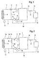
- FIG. 1 shows an example of a conventional cooling system.
- an internal combustion engine 1 is traversed by a coolant.
- the coolant flows out via a line 2 from the internal combustion engine 1 and flows through a three-way radiator valve 3, via a bypass branch 4, a coolant pump 5 and a line 6 back into the internal combustion engine 1.
- a portion of the coolant starting from the three-way radiator valve 3, over a line 7 to a radiator 8, from there via a line 9 and also via the coolant pump 5 and line 6 back to the internal combustion engine. 1
- the coolant leaves the internal combustion engine 1 via a line 10 and flows from there via a heating valve 11, a line 12, a heating heat exchanger 13, a line 14, the coolant pump 5 and line 6 back to the internal combustion engine 1.
- the line 10, the Heating valve 11, the line 12, the Schuungstrermübertrager 13 and the line 14 form a heating branch.
- FIG. 1 Furthermore, three temperature sensors are shown, which detect the temperatures at certain points of the cooling system. These are the temperature sensor 15, which detects the temperature in line 2, the temperature sensor 16, which detects the temperature in line 6, and the temperature sensor 17, which detects the temperature in line 9.
- the temperature sensor 15 thus detects the temperature at an output of the internal combustion engine 1.
- the temperature sensor 16 thus detects the temperature at an input of the Internal combustion engine 1
- the temperature sensor 17 thus detects the temperature of the coolant at an outlet of the radiator fan 8.
- FIG. 2 shows a cooling system according to the invention.
- the three-way radiator valve 3 shown there is replaced by two separate valves 3a and 3b.
- a cooler valve 3a is inserted into the line 7, whereby the line 7 is divided into two sub-lines 7a and 7b.
- a bypass valve 3b has been inserted, whereby the conduit 4 is divided into the parts 4a and 4b.
- the cooler valve 3, the partial lines 7a, 7b, the radiator 8 and the line 9 form a cooler branch.
- the bypass valve 3 and the sub-lines 4a, 4b form a bypass branch.
- the desired mixing ratio and the total nominal coolant flow can be set. If necessary, it must be assumed in this case that all the other branches short-circuiting the coolant pump 5 can likewise be disconnected, for example the heating branch 10-14.
- the desired mixing ratio between the radiator branch 3, 7a, 7b, 8, 9 and the bypass branch 3b, 4a, 4b as well as on the determination of the total coolant flow through the entire cooling system is not discussed in the context of this invention, since this is not relevant to the essence of the invention and this data can be determined in a separate thermal management process management.
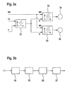
- FIG. 3a shows a first embodiment of the method according to the invention. Here, it is shown schematically how from the desired mixing ratio and the total target coolant flow, the corresponding positions of the two valves 3a and 3b after FIG. 2 be determined.
- the operating point of the coolant pump 5 is determined as a function of the rotational speed n of the internal combustion engine 1, and the desired hydraulic system resistance R is determined as a function of the total target coolant flow Vp by means of a first characteristic map 31.
- This desired hydraulic system resistance R and a desired mixing ratio MV are the inputs of the second and third maps 32, 33. From the second map 32 out the cooling valve 3a and from the third map 33 out the bypass valve 3b is driven. Accordingly, signals are obtained from the two characteristic diagrams 32, 33 which correspond to the desired positions of the valves 3a, 3b.
- FIG. 3b shows the same embodiment in a different representation.
- a first step 34 the input variables setpoint mixing ratio MV, total setpoint coolant flow Vp and rotational speed n of the internal combustion engine 1 are detected. Based on these input data, the hydraulic total resistance R of the cooling system is determined in a step 35 by means of the total target coolant flow Vp and the rotational speed n. This total hydraulic resistance R is transmitted to step 36, wherein, based on the desired mixing ratio MV and the total target refrigerant flow Vp drive quantities for the cooling valve 3a and the bypass valve 3b are determined. Finally, in the final step 37, the radiator valve 3a and the bypass valve 3b are activated accordingly.
- the first map 31 for determining the desired hydraulic resistance R and optionally the second and third maps 32, 33 can be generated automatically during the application of the internal combustion engine.
- the map of the coolant pump 5 must be known, which indicates the pressure difference across the pump dependence of the coolant flow and the pump or engine speed.
- the hydraulic resistances of the components should be known. In the case of the pump map, a hydraulic resistance can be clearly found for each data pair of coolant flow and speed.
- the respective valve or throttle body position must be stored in the respective map depending on the desired mixing ratio and the desired hydraulic resistance.
- a hydraulic equivalent resistance R of the cooling system can be determined by means of a hydraulic network analogous to electrical engineering, as long as the hydraulic resistances of the components and the resistance characteristics of the valves 3a, 3b are known.
- FIG. 1 An example of such a hydraulic network according to the invention is shown in FIG.
- the individual resistances of the components add up analogously to an electrical circuit for total resistance. This results in the system characteristic.
- the sought total coolant flow of the cooling system through the coolant pump 5 then results from the intersection of the pump curve with the system curve.
- FIG. 4 illustrated: the hydraulic resistance 41 of the internal combustion engine 1, the hydraulic resistance 42 of the heating branch 10-14, the hydraulic resistance 43 of a cylinder head, not shown in detail, contained in the internal combustion engine 1, the hydraulic resistance 44 of the bypass valve 3b, the hydraulic resistance 45 of the bypass branch 4a, 4b without the bypass valve 3b, the hydraulic resistance 46 of the radiator valve 3a and the hydraulic resistance 47 of the remaining radiator branch 7a, 7b, 8, 9 without the radiator valve 3a.
- the hydraulic resistors 44, 45 of the bypass valve 3b and the remaining bypass branch 4a, 4b are connected in series. This series circuit is in turn connected in parallel to the series circuit of hydraulic resistance 46 of the radiator valve 3a and hydraulic resistor 47 of the remaining radiator branch 7a, 7, 8, 9.
- FIG. 5 shows characteristics to determine the desired hydraulic resistance.
- Vp On the horizontal axis coolant flows Vp are shown, while on the vertical axis pressure differences dp are shown.
- n1, n2 and n3 pump characteristics 51, 52, 53 are respectively shown.
- system characteristic curve 54 which results (in the case of turbulent flow) from the multiplication of the hydraulic resistance R by the square of the coolant flow Vp.
- the system characteristic 54 represents a parabola, where the pressure difference dp is a function of the square of the refrigerant flow Vp, where the square of the refrigerant flow Vp is linked to the hydraulic resistance R as a factor.
- the slope of the system characteristic curve 54 thus becomes smaller and finally results in a system-dependent minimum hydraulic resistance R sys min, the dependence of which on the coolant flow Vp is provided with the reference number 55. If, on the other hand, the hydraulic resistance R increases, the system characteristic curve 54 will increase in size, and the system characteristic curve 54 would continue to shift in the direction of the vertical axis. Knowing the current speed n of the internal combustion engine 1 and a desired total desired coolant flow Vp can thus be determined from the intersection of the sought coolant flow Vp with the corresponding pump curve 51-53 the desired system characteristic, from which the sought hydraulic resistance R can be determined. For example, in the illustration after FIG.
- the illustrated method according to the invention can be integrated, for example, in a control unit of a motor vehicle, which additionally assumes, for example, the task of controlling the internal combustion engine 1.
- the functional relationships shown may, for. B. be represented by corresponding mathematical functions, a multi-dimensional map or by multiple maps in the engine control unit.
- the for the application required data are easily measurable, but should also be known or made known in the context of cooling system dimensioning by the vehicle manufacturer or by the component supplier.
Landscapes
- Engineering & Computer Science (AREA)
- Chemical & Material Sciences (AREA)
- Combustion & Propulsion (AREA)
- Mechanical Engineering (AREA)
- General Engineering & Computer Science (AREA)
- Combined Controls Of Internal Combustion Engines (AREA)
Claims (8)
- Procédé de commande et/ou de régulation d'un système de refroidissement d'un moteur à combustion interne (1) d'un véhicule automobile selon lequel,
un agent de refroidissement circule avec une pompe d'agent de refroidissement (5) et traverse à l'extérieur du moteur à combustion interne (1) au moins une branche de radiateur (3a, 7a, 7b, 8, 9) et une branche de dérivation (3b, 4a, 4b),- des moyens de commande et/ou de régulation assure indépendamment l'étranglement d'un courant d'agent de refroidissement à travers la branche du radiateur (3a, 74a, 7b, 8, 9) et d'un courant d'agent de refroidissement à travers la branche de dérivation (3b, 4a, 4b),caractérisé en ce que- à l'aide des moyens de commande et/ou de régulation, on règle un débit global prédéterminé (Vp) de l'agent de refroidissement,- à l'aide des moyens de commande et/ou de régulation, on règle un rapport de mélange prédéfini entre les courants d'agent de refroidissement à travers le radiateur et dans la branche de dérivation (3a, 7a, 7b, 8, 9; 3b, 4a, 4b),- partant du débit total prédéfini (Vp) d'agent de refroidissement, du rapport de mélange prédéfini (MV) et de la vitesse de rotation (n) du moteur à combustion interne (1), on détermine la résistance hydraulique totale (R) du système de refroidissement, et- on définit des grandeurs de commande pour la vanne de radiateur (3a, 7a, 7b, 8) et la vanne de dérivation (3b, 4a, 4b). - Procédé selon la revendication 1,
caractérisé en ce qu'
à l'aide d'une commande prédéfinie des moyens de commande et/ou de régulation, on règle la température de l'agent de refroidissement - Procédé selon les revendications précédentes,
caractérisé en ce qu'
au moins à partir du rapport de mélange prédéfini, du débit total prédéfini (Vp) d'agent de refroidissement et de la vitesse de rotation (n) du moteur à combustion interne (1) et/ou de la pompe d'agent de refroidissement (5) et/ou de la position de la vanne de chauffage (11), on définit des grandeurs de commande pour les moyens de commande et/ou de régulation. - Procédé selon la revendication 3,
caractérisé en ce qu'
à partir du débit total prédéfini (Vp) d'agent de refroidissement et de la vitesse de rotation (n) du moteur à combustion interne (1) et/ou de la pompe d'agent de refroidissement (5), on détermine la résistance hydraulique totale (R) du système de refroidissement. - Procédé selon la revendication 3 ou 4,
caractérisé en ce qu'
à partir des champs de caractéristiques (31, 32, 33), on détermine des grandeurs de commande pour la vanne de radiateur (3a) dans la branche de radiateur (3a, 7a, 7b, 8, 9) et pour la vanne de dérivation (3b) de la branche de dérivation (3b, 4a, 4b). - Procédé selon les revendications 4 et 5,
caractérisé en ce que
les champs de caractéristiques (31, 32, 33) sont enregistrés dans une mémoire au moins en fonction du rapport de mélange prédéfini et de la résistance hydraulique totale (R) du système de refroidissement. - Procédé selon la revendication 4,
caractérisé en ce qu'
un champ de caractéristiques (31, 32, 33) est enregistré dans une mémoire pour déterminer la résistance hydraulique totale (R) du système de refroidissement. - Commande et/ou régulation d'un système de refroidissement d'un moteur à combustion interne (1) d'un véhicule automobile comportant une pompe d'agent de refroidissement (5) pour faire circuler un agent de refroidissement, au moins une branche de radiateur (3a, 37a, 7b, 8, 9) et une branche de dérivation (3b, 4a, 4b) à travers lesquelles l'agent de refroidissement peut circuler à l'extérieur du moteur à combustion interne (1),- comprenant des moyens de commande et/ou de régulation avec étranglement d'un courant d'agent de refroidissement à travers la branche de radiateur (3a, 7a, 7b, 8, 9) et d'un courant d'agent de refroidissement à travers la branche de dérivation (3b, 4a, 4b) indépendamment l'un de l'autre,caractérisée en ce que
les moyens de commande et/ou de régulation règlent un débit total prédéfini (Vp) d'agent de refroidissement,- les moyens de commande et/ou de régulation règlent un rapport de mélange prédéfini des courant d'agent de refroidissement à travers le radiateur et la branche de dérivation (3a, 7a, 7b, 8, 9; 3b, 4a, 4b),- à partir du débit total prédéfini (Vp) d'agent de refroidissement, du rapport de mélange prédéfini (MV) et de la vitesse de rotation (n) du moteur à combustion interne (1), on détermine une résistance hydraulique totale (R) du système de refroidissement, et- on définit les grandeurs de commande pour la vanne de radiateur (3a, 7a, 7b, 8) et de la vanne de dérivation (3b, 4a, 4b).
Applications Claiming Priority (5)
| Application Number | Priority Date | Filing Date | Title |
|---|---|---|---|
| DE10216646 | 2002-04-15 | ||
| DE10216646 | 2002-04-15 | ||
| DE2003116017 DE10316017A1 (de) | 2003-04-07 | 2003-04-07 | Verfahren zur Steuerung und/oder Regelung eines Kühlsystems einer Brennkraftmaschine eines Kraftfahrzeugs |
| DE10316017 | 2003-04-07 | ||
| PCT/DE2003/001228 WO2003087552A1 (fr) | 2002-04-15 | 2003-04-11 | Procede permettant de commander et/ou de reguler un systeme de refroidissement d'un moteur a combustion interne d'un vehicule automobile |
Publications (2)
| Publication Number | Publication Date |
|---|---|
| EP1497540A1 EP1497540A1 (fr) | 2005-01-19 |
| EP1497540B1 true EP1497540B1 (fr) | 2008-10-01 |
Family
ID=29251760
Family Applications (1)
| Application Number | Title | Priority Date | Filing Date |
|---|---|---|---|
| EP03746236A Expired - Lifetime EP1497540B1 (fr) | 2002-04-15 | 2003-04-11 | Procede permettant de commander et/ou de reguler un systeme de refroidissement d'un moteur a combustion interne d'un vehicule automobile |
Country Status (3)
| Country | Link |
|---|---|
| EP (1) | EP1497540B1 (fr) |
| DE (1) | DE50310574D1 (fr) |
| WO (1) | WO2003087552A1 (fr) |
Families Citing this family (1)
| Publication number | Priority date | Publication date | Assignee | Title |
|---|---|---|---|---|
| GB2475079B (en) * | 2009-11-05 | 2015-02-18 | Ford Global Tech Llc | Cooling systems |
Family Cites Families (4)
| Publication number | Priority date | Publication date | Assignee | Title |
|---|---|---|---|---|
| DE4033261C2 (de) * | 1990-10-19 | 1995-06-08 | Freudenberg Carl Fa | Temperaturgesteuerter Kühlkreis einer Verbrennungskraftmaschine |
| US6178928B1 (en) * | 1998-06-17 | 2001-01-30 | Siemens Canada Limited | Internal combustion engine total cooling control system |
| FR2804721B1 (fr) * | 2000-02-03 | 2002-06-21 | Peugeot Citroen Automobiles Sa | Dispositif de refroidissement d'un moteur de vehicule automobile |
| JP4337207B2 (ja) * | 2000-02-10 | 2009-09-30 | 株式会社デンソー | 液冷式内燃機関の冷却装置 |
-
2003
- 2003-04-11 WO PCT/DE2003/001228 patent/WO2003087552A1/fr not_active Ceased
- 2003-04-11 DE DE50310574T patent/DE50310574D1/de not_active Expired - Lifetime
- 2003-04-11 EP EP03746236A patent/EP1497540B1/fr not_active Expired - Lifetime
Also Published As
| Publication number | Publication date |
|---|---|
| EP1497540A1 (fr) | 2005-01-19 |
| WO2003087552A1 (fr) | 2003-10-23 |
| DE50310574D1 (de) | 2008-11-13 |
Similar Documents
| Publication | Publication Date | Title |
|---|---|---|
| DE602004004016T3 (de) | Verfahren zur Ventilsteuerung eines Abgassystems | |
| DE10359581B4 (de) | Verfahren zur Steuerung eines Fahrzeugmotorkühlsystems | |
| DE19754461B4 (de) | Kraftübertragungssteuerung für ein Automobil | |
| DE10224063A1 (de) | Verfahren zur Wärmeregulierung einer Brennkraftmaschine für Fahrzeuge | |
| EP1454039B1 (fr) | Procede de regulation de la temperature d'un moteur | |
| DE10210586A1 (de) | Verfahren und Vorrichtung für einen Kühlventilatorsteueralgorithmus | |
| EP0814327A1 (fr) | Méthode pour obtenir une saisie correcte de la température extérieure | |
| EP1399656B1 (fr) | Procede de surveillance d'un circuit de refroidissement dans un moteur a combustion interne | |
| DE112018002922B4 (de) | Kühlvorrichtung und Kühlverfahren für einen Verbrennungsmotor mit einem EGR-System | |
| DE10157714A1 (de) | Verfahren und Vorrichtungen zur Durchführung des Verfahrens zum Beeinflussen der Betriebstemperatur eines hydraulischen Betriebsmittels für ein Antriebsaggregat eines Fahrzeuges | |
| DE102005062294A1 (de) | Verfahren zur Kühlung einer Brennkraftmaschine | |
| EP2507080B1 (fr) | Véhicule doté d'un circuit de réfrigérant servant à distribuer la chaleur à des organes de véhicule | |
| WO2019149792A1 (fr) | Procédé destiné à régler une température d'un réfrigérant d'un circuit de réfrigérant d'une unité d'entraînement sur un banc d'essai | |
| DE19500648B4 (de) | Kühlanlage für einen Verbrennungsmotor eines Kraftfahrzeuges mit einem Thermostatventil | |
| DE68906971T2 (de) | Ruck-kontrollsystem fuer ein antriebssystem. | |
| DE112015004273T5 (de) | Steuervorrichtung und Verfahren für ein Kühlsystem | |
| DE10316017A1 (de) | Verfahren zur Steuerung und/oder Regelung eines Kühlsystems einer Brennkraftmaschine eines Kraftfahrzeugs | |
| EP0885758B1 (fr) | Méthode d'opération d'un échangeur de chaleur des gaz d'échappement d'un moteur à combustion interne de véhicules automobiles | |
| DE3610962C1 (de) | Verfahren zum Regeln der Innenraumtemperatur,insbesondere eines Kraftfahrzeugs | |
| DE60123402T2 (de) | Verfahren und einrichtung zur kühlung einer brennkraftmaschine eines kraftfahrzeugs | |
| EP1497540A1 (fr) | Procede permettant de commander et/ou de reguler un systeme de refroidissement d'un moteur a combustion interne d'un vehicule automobile | |
| DE102007006341A1 (de) | Verfahren zur Steuerung einer Brennkraftmaschine in Kraftfahrzeugen | |
| EP0888913B1 (fr) | Ensemble de flux thermique dans des véhicules à moteur | |
| EP2360041B1 (fr) | Agencement de circuit | |
| DE112008001317B4 (de) | Verfahren, Anordnung und Computerprogrammprodukt zum Steuern eines VTG-Motors |
Legal Events
| Date | Code | Title | Description |
|---|---|---|---|
| PUAI | Public reference made under article 153(3) epc to a published international application that has entered the european phase |
Free format text: ORIGINAL CODE: 0009012 |
|
| 17P | Request for examination filed |
Effective date: 20041115 |
|
| AK | Designated contracting states |
Kind code of ref document: A1 Designated state(s): AT BE BG CH CY CZ DE DK EE ES FI FR GB GR HU IE IT LI LU MC NL PT RO SE SI SK TR |
|
| 17Q | First examination report despatched |
Effective date: 20071102 |
|
| GRAP | Despatch of communication of intention to grant a patent |
Free format text: ORIGINAL CODE: EPIDOSNIGR1 |
|
| GRAS | Grant fee paid |
Free format text: ORIGINAL CODE: EPIDOSNIGR3 |
|
| GRAA | (expected) grant |
Free format text: ORIGINAL CODE: 0009210 |
|
| AK | Designated contracting states |
Kind code of ref document: B1 Designated state(s): DE FR GB IT |
|
| REG | Reference to a national code |
Ref country code: GB Ref legal event code: FG4D Free format text: NOT ENGLISH |
|
| REF | Corresponds to: |
Ref document number: 50310574 Country of ref document: DE Date of ref document: 20081113 Kind code of ref document: P |
|
| PLBE | No opposition filed within time limit |
Free format text: ORIGINAL CODE: 0009261 |
|
| STAA | Information on the status of an ep patent application or granted ep patent |
Free format text: STATUS: NO OPPOSITION FILED WITHIN TIME LIMIT |
|
| 26N | No opposition filed |
Effective date: 20090702 |
|
| PGFP | Annual fee paid to national office [announced via postgrant information from national office to epo] |
Ref country code: GB Payment date: 20140423 Year of fee payment: 12 |
|
| PGFP | Annual fee paid to national office [announced via postgrant information from national office to epo] |
Ref country code: IT Payment date: 20140429 Year of fee payment: 12 Ref country code: FR Payment date: 20140416 Year of fee payment: 12 |
|
| GBPC | Gb: european patent ceased through non-payment of renewal fee |
Effective date: 20150411 |
|
| PG25 | Lapsed in a contracting state [announced via postgrant information from national office to epo] |
Ref country code: IT Free format text: LAPSE BECAUSE OF NON-PAYMENT OF DUE FEES Effective date: 20150411 Ref country code: GB Free format text: LAPSE BECAUSE OF NON-PAYMENT OF DUE FEES Effective date: 20150411 |
|
| REG | Reference to a national code |
Ref country code: FR Ref legal event code: ST Effective date: 20151231 |
|
| PG25 | Lapsed in a contracting state [announced via postgrant information from national office to epo] |
Ref country code: FR Free format text: LAPSE BECAUSE OF NON-PAYMENT OF DUE FEES Effective date: 20150430 |
|
| PGFP | Annual fee paid to national office [announced via postgrant information from national office to epo] |
Ref country code: DE Payment date: 20160628 Year of fee payment: 14 |
|
| REG | Reference to a national code |
Ref country code: DE Ref legal event code: R119 Ref document number: 50310574 Country of ref document: DE |
|
| PG25 | Lapsed in a contracting state [announced via postgrant information from national office to epo] |
Ref country code: DE Free format text: LAPSE BECAUSE OF NON-PAYMENT OF DUE FEES Effective date: 20171103 |