EP1497564B1 - Conduite a rainure spiralee - Google Patents
Conduite a rainure spiralee Download PDFInfo
- Publication number
- EP1497564B1 EP1497564B1 EP03722783A EP03722783A EP1497564B1 EP 1497564 B1 EP1497564 B1 EP 1497564B1 EP 03722783 A EP03722783 A EP 03722783A EP 03722783 A EP03722783 A EP 03722783A EP 1497564 B1 EP1497564 B1 EP 1497564B1
- Authority
- EP
- European Patent Office
- Prior art keywords
- duct
- lobes
- zone
- lobed
- cross
- Prior art date
- Legal status (The legal status is an assumption and is not a legal conclusion. Google has not performed a legal analysis and makes no representation as to the accuracy of the status listed.)
- Expired - Lifetime
Links
- 230000007704 transition Effects 0.000 claims abstract description 59
- 239000000203 mixture Substances 0.000 claims abstract description 39
- 238000000034 method Methods 0.000 claims description 26
- 238000012545 processing Methods 0.000 claims description 10
- 230000007423 decrease Effects 0.000 claims description 8
- 230000003247 decreasing effect Effects 0.000 claims description 6
- 230000001939 inductive effect Effects 0.000 claims description 2
- 239000012071 phase Substances 0.000 description 14
- 239000002002 slurry Substances 0.000 description 14
- 239000012530 fluid Substances 0.000 description 9
- 239000002245 particle Substances 0.000 description 9
- 230000008901 benefit Effects 0.000 description 6
- 230000000694 effects Effects 0.000 description 6
- 230000003628 erosive effect Effects 0.000 description 6
- 238000011144 upstream manufacturing Methods 0.000 description 6
- 230000001965 increasing effect Effects 0.000 description 5
- 230000037390 scarring Effects 0.000 description 5
- 239000000725 suspension Substances 0.000 description 5
- 238000013461 design Methods 0.000 description 4
- 238000005086 pumping Methods 0.000 description 4
- 230000009467 reduction Effects 0.000 description 3
- 230000000903 blocking effect Effects 0.000 description 2
- 230000017531 blood circulation Effects 0.000 description 2
- 230000008859 change Effects 0.000 description 2
- 239000007788 liquid Substances 0.000 description 2
- 239000007791 liquid phase Substances 0.000 description 2
- 238000004519 manufacturing process Methods 0.000 description 2
- 239000007787 solid Substances 0.000 description 2
- XLYOFNOQVPJJNP-UHFFFAOYSA-N water Substances O XLYOFNOQVPJJNP-UHFFFAOYSA-N 0.000 description 2
- 238000013459 approach Methods 0.000 description 1
- 239000011324 bead Substances 0.000 description 1
- 230000009286 beneficial effect Effects 0.000 description 1
- 238000002474 experimental method Methods 0.000 description 1
- 239000008240 homogeneous mixture Substances 0.000 description 1
- 229910052500 inorganic mineral Inorganic materials 0.000 description 1
- 238000012423 maintenance Methods 0.000 description 1
- 239000011707 mineral Substances 0.000 description 1
- 238000005065 mining Methods 0.000 description 1
- 230000008569 process Effects 0.000 description 1
- 230000000750 progressive effect Effects 0.000 description 1
- 231100000241 scar Toxicity 0.000 description 1
- 238000004062 sedimentation Methods 0.000 description 1
Images




Classifications
-
- F—MECHANICAL ENGINEERING; LIGHTING; HEATING; WEAPONS; BLASTING
- F16—ENGINEERING ELEMENTS AND UNITS; GENERAL MEASURES FOR PRODUCING AND MAINTAINING EFFECTIVE FUNCTIONING OF MACHINES OR INSTALLATIONS; THERMAL INSULATION IN GENERAL
- F16L—PIPES; JOINTS OR FITTINGS FOR PIPES; SUPPORTS FOR PIPES, CABLES OR PROTECTIVE TUBING; MEANS FOR THERMAL INSULATION IN GENERAL
- F16L9/00—Rigid pipes
- F16L9/006—Rigid pipes specially profiled
-
- F—MECHANICAL ENGINEERING; LIGHTING; HEATING; WEAPONS; BLASTING
- F15—FLUID-PRESSURE ACTUATORS; HYDRAULICS OR PNEUMATICS IN GENERAL
- F15D—FLUID DYNAMICS, i.e. METHODS OR MEANS FOR INFLUENCING THE FLOW OF GASES OR LIQUIDS
- F15D1/00—Influencing flow of fluids
- F15D1/02—Influencing flow of fluids in pipes or conduits
- F15D1/06—Influencing flow of fluids in pipes or conduits by influencing the boundary layer
- F15D1/065—Whereby an element is dispersed in a pipe over the whole length or whereby several elements are regularly distributed in a pipe
Definitions
- This invention relates to a duct, a processing plant in which a two-phase mixture is fed from a duct substantially tangentially into a processing apparatus and a method of reducing localised wear in a duct, as defined in the pre-ambles of claims 1, 28 and 29, respectively..
- Figure 1 is a graph of head loss (pressure drop) against velocity in a duct conveying a two-phase liquid/particulate mixture, and it illustrates three flow regimes associated with such a mixture, for example a slurry.
- a settling, sedimentation, regime where the slurry is not moving with sufficient mean velocity to prevent the settling of a more dense particulate phase from the slurry onto horizontal surfaces of a duct. This occurs when the mean velocity of the slurry falls below a critical velocity, v c , and it leads to a progressive build-up of solids and eventual blocking of the duct.
- the critical velocity is a velocity close to, but not necessarily coincident with, the velocity at the minimum on the pressure /velocity curve ( Figure 1 ).
- Above the critical velocity there is an asymmetric flow regime, where the denser phase is asymmetrically distributed within the liquid in that it preferentially resides in the lower part of the duct but still flows along the duct, some of the particles being entrained within the liquid phase of the slurry in the upper part of the duct.
- there is a symmetric flow regime where the particulate phase of the slurry is substantially homogeneously distributed and entrained in the liquid phase of the slurry.
- the wear rate experienced by the internal surfaces of a duct varies approximately as v 3.5 .
- v 3.5 the wear rate experienced by the internal surfaces of a duct varies approximately as v 3.5 .
- it also reduces the working life of a plant or contributes to high maintenance costs. It is accordingly desirable to reduce the flow velocity in order to increase the lifetime of the duct.
- This is particularly true of a curved section in a duct where there is preferential wear on an outer wall of the curved section of the duct due to the denser phase striking the wall head on. This leads to increased wear on the outer wall resulting in scarring, or pitting, of the wall.
- the concave curvature of the bend may focus rebounding particles onto a point on the intrados of the bend. This also has the potential to create scar damage. Any scarring will promote turbulence in the slurry which accelerates the rate of wear of the surface even further, eventually leading to failure of the duct at the site of the scarring.
- WO 00/38591 discloses blood flow tubing and a method of artificial or modified natural blood flow.
- the tubing has helical-flow inducing means adapted to induce helical flow.
- This arrangement allows control over particulate distribution within a carrier fluid flowing in a downstream direction through such a transition zone towards a lobed region of the duct to a greater extent than prior art arrangements and thus allows particle suspension, for example in an asymmetric flow regime, to be achieved at a lower velocity than would otherwise be the case. Power losses due to changes in duct cross-sectional area are substantially avoided.
- the pumping power required to achieve particle suspension is less than would be the case if the particles were in a bed at the bottom the pipe, because relatively high axial velocities would not be required to achieve this state of suspension.
- the axial velocity could approach that required to merely transport the particulate slurry.
- the helix goes clockwise in the downstream fluid flow direction, and in other embodiments of the invention, the helix goes anticlockwise.
- the transition from circular to lobed cross-section is smooth and continuous and takes place over a said transition zone occupying a duct length in which the or each lobe becomes relocated by at least one position.
- the least amount by which the position of any given lobe will have been rotated to satisfy this condition in going from the upstream to the downstream cross-section is that which gives a (first) non-overlapping relationship between the two positions of such lobe.
- the minimum angle through which a given lobe must have been relocated will be 120°.
- each lobe will overlap with the position which a neighbouring lobe occupied at the upstream cross-section.
- the minimum angle will be / n 360 ⁇ ° .
- the minimum relocation angle is suitably 90°.
- the arrangement allows the control over the distribution of particulates within a mixture without significantly increasing turbulence in a system, and it promotes a low cost in terms of pressure drop at the transition zone.
- transition zone occupies a duct length which is at least 5 D / n and preferably 6.8 D / n where D is again the diameter of the immediately preceding circular duct length portion, and n is the number of lobes.
- transition zone is efficient in generating swirl in the mixture being conveyed, and that it is usually unnecessary for said transition zone to occupy a duct length which gives more than one complete revolution of the helical lobe in order to avoid any significant increase in turbulence within the mixture being conveyed along the duct: thus the adoption of this feature is accordingly preferred.
- such a lobed zone has a substantially constant cross-sectional area. And that is sometimes substantially equal to the cross-section of the preceding circular duct length portion when the transition zone itself is of substantially constant cross-sectional area.
- the duct includes a bend in a helically lobed zone thereof.
- the duct may include a plurality of bends each of which is located in a helically lobed zone thereof.
- the present invention is particularly advantageous in the presence of a bend in that there is a reduction in localised wear at an outer wall of the bend due to a more even distribution of particles within the mixture. This can lead to a more even distribution of wear in the regions adjacent the bend and may even result in an overall reduction in the amount of wear of the duct.
- the or at least one helically lobed zone of the duct which is located spaced from the end thereof is followed by a second transition zone in which the lobed cross-section reverts to a circular cross-section. More preferably the cross-sectional area of the duct remains substantially constant over said second transition zone.
- said second transition zone occupies a duct length which is from 5/ n to 11/ n , for example from 6.8/ n to 8.5/ n times the duct diameter, where n is the number of lobes.
- the pitch of the helical lobes in the first transition zone decreases towards the lobed portion.
- the pitch of the helical lobes in the lobed zone remains substantially constant.
- the pitch of the helical lobes in the second transition zone may also remain substantially constant.
- such constant helical pitch is between 5 and 11 times the diameter of the circular duct section. More preferably such constant helical pitch is between 6.8 and 8.5 times the diameter of the circular duct section.
- the optimal pitch-to-diameter ratio for the helix may, in fact, be subject to some variation in value for a helix of constant pitch.
- the optimum P / D is close to 6:1.
- the optimum appears to be around 8:1.
- the optimum P / D value was again 8:1.
- the lobes may be equiangularly spaced about the, or each, lobed zone.
- the cross-sectional shapes of the lobes are defined by circular arcs drawn on chords defining a notional polygon.
- the shapes of the lobes are defined by semicircles drawn on chords defined by a notional polygon.
- the notional polygon is a regular polygon.
- This method reduces localised wear, particularly but not exclusively at a bend in the duct, by reducing the proportion of particulates in the mixture that strike a wall of the duct perpendicularly, or near perpendicularly, to the direction of the flowpath.
- the method may include providing a bend in the duct in a zone of the duct where there is a lobe.
- the method includes providing a transition zone in the duct wherein variation of the cross-sectional shape of the duct commences.
- the method includes varying the cross-sectional shape of the duct from circular to lobed.
- the method may include extending the lobe in a helical manner along the flowpath, typically by 90°.
- the method may include increasing the size of the lobe along the flowpath.
- the method may include providing a plurality of lobes spaced about an inner surface of the duct.
- the method may include spacing the lobes equiangularly about the duct.
- Any method according to the invention includes maintaining a constant cross-sectional area of the flowpath whilst varying said cross-sectional shape.
- the method may include extending the lobe in a helical manner along the flowpath, typically by 90°.
- the method may include providing a plurality of lobes spaced about an inner surface of the duct.
- the method may include spacing the lobes equiangularly about an inner circumference of the duct.
- the method may include providing a bend in the duct in a zone of the duct where there is a lobe.
- the above method is advantageous not only in placing the two phase mixture in a suspension but also in exerting a degree of control over where a region of high concentration of particulates is located within the duct in the asymmetrical flow regime. This is particularly important in the case of entry of the mixture into, for example, a cyclone where the particles should be concentrated about the wall of the duct.
- a processing plant in which a two phase mixture is fed from a duct substantially tangentially into a processing apparatus, as defined in claim 28.
- a duct 10 has a first zone 12 of circular cross-section and a second, transition zone 14.
- the transition zone 14 has a length which is from 5 to 11 times the diameter of the first zone 12 and has a radial lobe 16 in a wall 18 of the duct 10. In this way, the transition zone is given a duct length in which the lobe becomes relocated by at least one position, and as shown, the single lobe is relocated through an angle of 90°.
- the lobe 16 is typically arcuate, usually part circular, in cross-sectional shape and the radius of the arc decreases as the transition zone 14 is traversed.
- the lobe 16 is illustrated as being formed within the thickness of the wall 18 of the duct. In fact, it will usually be more convenient to manufacture the duct with a substantially constant wall thickness so the presence of a concave lobe in the interior wall surface is reflected in a convex lobe on the exterior of the duct.
- the lobe 16 extends helically along the length of the transition zone 14 such that the lobe 16 starts to grow from the lowest point of the duct 10 and terminates approximately at its mid-point, i.e. 90° of pitch.
- the transition from circular to lobe cross-section is typically smooth and continuous in accordance with the second aspect of the invention.
- the effect of the lobe 16 is to impart a component of velocity to a two phase mixture, or other fluid, flowing along a flow-path A-A, that is tangential to that flowpath A-A, causing the mixture to swirl within the duct 10.
- the helical pitch of the lobe 16 is important in that decreasing the pitch increases the tangential component of the flow rate of the mixture. It has been found that the ratio of the pitch of the helix to the diameter of the duct 10 that is most effective in causing the mixture to swirl is between 5:1 and 11:1, with pitch ratios in the range 6.8:1 to 8.5:1 being particularly effective.
- the cross-sectional area of the flow path A-A through the duct 10 is maintained substantially constant by reducing the diameter of the flow orifice of the duct as the size of the lobes 16 increases. This maintains a nominally constant rate of flow of the mixture through the duct 10.
- the orifice diameter can be maintained constant so as to increase the overall cross-sectional area of the duct over the transition zone 14 as the size of the lobe 16 increases. This has the effect of counteracting a hydraulic gradient due to a fraction of the mixture not travelling forward and having a significant tangential component to its velocity.
- a duct 20 comprises a plain zone 22, a first transition zone 24, a constant helical zone 26, a second transition zone 28 and a second plain zone 30.
- the flow-path of a two phase mixture, or other fluid, through the duct 20 is indicated by the line B-B.
- Mixture entering the first transition zone 24 from the plain zone 22 encounters a lobe of increasing size and optionally decreasing pitch as the flow-path is traversed.
- the decreasing pitch of the lobe increases the tangential component of the velocity that is imparted to the mixture.
- the lobe is maintained at constant size and pitch within the constant helical zone 26.
- the second transition zone 28 has decreasing lobe size with the pitch of the helix about the internal circumference of the duct 20 preferably being maintained constant until the lobe peters out and the second plain zone 30 is reached.
- This arrangement allows the introduction of a tangential component of velocity to the mixture by the use of only a small zone of helically lobed duct. It will be appreciated that the pitch of the lobe in the first transition zone 24 can be constant should a constant known velocity be required.
- a duct 32 comprising a transition zone 33 having three lobes 34a-c equiangularly spaced about its internal circumference.
- the lobes 34a-c increase in size as they extend helically about the circumference of the duct 32 along the transition zone 33.
- any number of lobes can be employed to introduce swirl into a mixture. However, it has been found that three or four lobe yields sufficient swirl to reduce the critical velocity, above which asymmetric flow occurs, for most slurries. Any further increase in the number of lobes results in small performance improvements with increased manufacturing complexity. More than seven lobes give no significant performance advantage over a seven lobed duct.
- Figure 5 shows a duct 36 comprising a first straight zone 38, a bend 40 and a second straight zone 42.
- the first straight zone 38 includes a transition zone 44, similar to that described in relation to Figure 3 , having four lobes 36a-d.
- the bend 40 maintains the lobes 46a-d at a constant helical pitch and at a constant size.
- the second straight zone 42 includes a transition zone 48 from helically rotating lobes 46a-d to a plain pipe 50 of circular cross-section.
- a two phase mixture that is introduced into the bend has swirl induced into it.
- the effect of the swirl is to distribute particulates in the mixture more evenly throughout the mixture. This has the effect of reducing the critical velocity, v c , at which asymmetric flow is achieved and hence reducing the pumping power that is required for the mixture to flow through the duct.
- the degree of erosion actually increases, though the erosion is more evenly distributed about the duct 36.
- particles entrained along the direction C-C of the first straight zone 38 strike an outer wall (extrados) 52 of the bend 40 such that a scarred zone 54 forms in the wall 52.
- the particulates already have a velocity component in the direction of the second straight zone 42. Therefore the particulates do not impinge directly upon the outer wall 52 but strike it obliquely thereby reducing the erosion and scarring of the wall 52.
- rebound such as might cause scarring of the intrados of the bend 40 is also reduced.
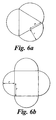
- the increase and decrease of the size lobes where the cross-section of the duct remains constant typically involves the definition of a circular arc struck upon a chord that forms the side of a regular polygon with the radius of the circle obeying, for example, the following relationships:
- r is the radius of a fully formed lobe and also half the length of the side of a suitable regular polygon; and d is the diameter of a plain cylindrical pipe of the cross-section to be maintained.
- a circle of diameter d can be considered as the cross-section of a plain duct.
- the circle circumscribes a square that forms the basis of the growth of lobes. Whilst keeping the cross-sectional area constant the length of the sides of the square decreases, the radius of curvature of the arc decreases so that the height of the lobe increases, until the limiting case detailed above in Equation 2 is reached.
- Figures 8a to 8k show a similar growth of lobes for a three lobed duct as that shown in Figures 7a to 7c , for a four lobed arrangement, including the effect of helical twist of the lobes.
- the cross-sectional area of the duct is maintained constant whilst the radius of curvature of the arc decreases and the height of the lobe increases until the limiting case detailed above in Equation 1 is reached.
- each lobe will overlap with the position which a neighbouring lobe occupied at the upstream cross-section.
- the minimum angle will be / n 360 ⁇ ° .
- Figure 9 illustrates a preferred form of the inner wall of a three-lobed duct section as it rounds a bend 90.
- the three lobes 91, 92, 93 are formed as semi-circles based on the three sides of a notional equilateral triangle 94, the three lobes being contiguous and meeting at cusps at the apices 95, 96, 97 of the triangle 94.
- the duct is of uniform cross-section as it rounds the bend, though of course that cross-section progressively rotates along the duct.
- the radius of curvature of the bend 90 (taken at the centre of the duct) is six times the equivalent diameter d of a circle corresponding to the duct section. Compare Equation 1. The benefits of the invention are most manifest when the radius of curvature of the centre line of the bend is at least 1.5 times such equivalent diameter.
- Figure 10 illustrates a right-angled bend 100 formed by a four-lobed duct section.
- Four lobes 101, 102, 103, 104 are formed as semi-circles based on the four sides of a notional square 105, the four lobes being contiguous and meeting at cusps at the corners of the square 94.
- the duct is of uniform cross-section as it rounds the bend, though of course that cross-section progressively rotates along the duct.
Landscapes
- Engineering & Computer Science (AREA)
- General Engineering & Computer Science (AREA)
- Mechanical Engineering (AREA)
- Physics & Mathematics (AREA)
- Fluid Mechanics (AREA)
- Rigid Pipes And Flexible Pipes (AREA)
- Laying Of Electric Cables Or Lines Outside (AREA)
- Measurement Of The Respiration, Hearing Ability, Form, And Blood Characteristics Of Living Organisms (AREA)
- Polyoxymethylene Polymers And Polymers With Carbon-To-Carbon Bonds (AREA)
- Sewage (AREA)
- Extrusion Moulding Of Plastics Or The Like (AREA)
- Dental Tools And Instruments Or Auxiliary Dental Instruments (AREA)
- Confectionery (AREA)
- Food-Manufacturing Devices (AREA)
- Duct Arrangements (AREA)
Claims (36)
- Conduite comportant au moins une partie de longueur (12 ; 22 ; 30) de section transversale circulaire, la conduite incluant en outre une zone (26 ; 40 ; g0 ; 100) dont la section transversale présente des lobes (16 ; 34 ; 46 ; g1 à g3 ; 101 à 104), ledit lobe ou chacun desdits lobes (16 ; 34 ; 46 ; g1 à g3 ; 101 à 104) s'étendant en hélice autour et le long de la conduite, et la conduite ayant une superficie de section transversale sensiblement constante sur une zone de transition (14 ; 24 ; 33 ; 44) dans laquelle la section transversale de conduite passe d'une forme circulaire à une forme en lobe, caractérisée en ce que, dans une dite zone de transition (24 ; 44) d'une section de conduite circulaire (22) à une zone en lobe (26 ; 40), les formes de section transversale des lobes (46), à des points donnés sur la longueur de la zone de transition (24 ; 44), sont définies par des arcs circulaires dessinés sur des cordes définissant une série de polygones imaginaires qui sont au moins similaires au sens géométrique, le rayon de courbure desdits arcs circulaires diminuant progressivement du rayon de conduite circulaire d'une extrémité circulaire de la zone de transition à la demi-longueur de corde de l'extrémité totalement en lobe de la zone de transition (24 ; 44).
- Conduite selon la revendication 1, dans laquelle la transition d'une section transversale circulaire à une section transversale en lobe est régulière et continue et se fait sur une dite zone de transition (14 ; 24 ; 33 ; 44) occupant une longueur de conduite dans laquelle chaque lobe (16 ; 34 ; 46 ; g1 à g3 ; 101 à 104) est décalé d'au moins une position.
- Conduite selon la revendication 2, dans laquelle chaque lobe (16 ; 34 ; 46 ; g1 à g3 ; 101 à 104) est décalé d'un maximum d'une révolution autour de la conduite.
- Conduite selon la revendication 2 ou 3, dans laquelle la zone de transition (14 ; 24 ; 33 ; 44) d'une forme circulaire à une forme en lobe occupe une longueur de conduite d'au moins 5 D/n, où D est le diamètre de la partie de longueur de conduite circulaire immédiatement précédente, et où n est le nombre de lobes.
- Conduite selon l'une quelconque des revendications 2 à 4, dans laquelle on trouve au moins trois lobes (34 ; 46 ; g1 à g3 ; 101 à 104), et dans laquelle ladite zone de transition (33 ; 44) occupe une longueur de conduite qui est inférieure ou égale à 11 D/n, où D et le diamètre de la partie de longueur de conduite circulaire immédiatement précédente, et où n est le nombre de lobes (34 ; 46 ; g1 à g3 ; 101 à 104).
- Conduite selon la revendication 5, dans laquelle ladite zone de transition (33 ; 44) occupe une longueur de conduite qui est inférieure ou égale à 8,5 D/n, où D est le diamètre de la partie de longueur de conduite circulaire immédiatement précédente, et où n est le nombre de lobes (34 ; 46 ; g1 à g3 ; 101 à 104).
- Conduite selon l'une quelconque des revendications précédentes, dans laquelle une telle zone en lobe (26 ; g0 ; 100) a une superficie de section transversale sensiblement constante qui est sensiblement égale à la partie de longueur de conduite circulaire qui précède (12 ; 22).
- Conduite selon l'une quelconque des revendications précédentes, dans laquelle la conduite inclut un coude dans une zone en lobe en hélice (40 ; g0 ; 100) de celle-ci.
- Conduite selon la revendication 8, dans laquelle la conduite inclut une pluralité de coudes dont chacun est situé dans une zone en lobe en hélice de celle-ci.
- Conduite selon l'une quelconque des revendications précédentes, dans laquelle la, ou au moins une, zone en lobe en hélice (26 ; 40) de la conduite qui est située espacée de son extrémité est suivie d'une seconde zone de transition (28 ; 48) dans laquelle la section transversale en lobe redevient une section transversale circulaire.
- Conduite selon la revendication 10, dans laquelle la superficie de section transversale de la conduite demeure sensiblement constante sur ladite seconde zone de transition (28 ; 48).
- Conduite selon la revendication 10 ou 11, dans laquelle ladite seconde zone de transition (28 ; 48) occupe une longueur de conduite qui a une valeur comprise entre 5/n et 11/n fois le diamètre de conduite, où n est le nombre de lobes (16 ; 34 ; 46 ; g1 à g3 ; 101 à 104).
- Conduite selon l'une quelconque des revendications précédentes, dans laquelle le pas des lobes en hélice de la première zone de transition (24 ; 46) diminue en direction de la partie en lobe (26).
- Conduite selon l'une quelconque des revendications 1 à 13, dans laquelle le pas des lobes en hélice de la zone en lobe (40) diminue dans une direction vers l'aval de la première zone de transition (44).
- Conduite selon l'une quelconque des revendications 1 à 13, dans laquelle le pas des lobes en hélice de la zone en lobe (26 ; g0 ; 100) reste sensiblement constant.
- Conduite selon l'une quelconque des revendications précédentes, dans laquelle le pas des lobes en hélice (46) de la seconde zone de transition (48) reste sensiblement constant.
- Conduite selon la revendication 15 ou 16, dans laquelle ce pas d'hélice constant a une valeur comprise entre 5 et 11 fois le diamètre de la section de conduite circulaire.
- Conduite selon la revendication 17, dans laquelle ce pas d'hélice constant a une valeur comprise entre 6,8 et 8,5 fois le diamètre de la section de conduite circulaire.
- Conduite selon l'une quelconque des revendications précédentes, dans laquelle il y a au moins trois lobes (34 ; 46 ; g1 à g3 ; 101 à 104) au niveau de l'une quelconque des zones en lobe donnée (26 ; 40 ; g0 ; 100).
- Conduite selon l'une quelconque des revendications précédentes, dans laquelle il y a au plus sept lobes (16 ; 34 ; 46 ; g1 à g3 ; 101 à 104) au niveau de l'une quelconque des zones en lobe donnée (26 ; 40 ; g0 ; 100).
- Conduite selon l'une ou l'autre des revendications 19 ou 20, dans laquelle il y a quatre lobes (46) au niveau de la, ou d'au moins une, zone en lobe (40).
- Conduite selon la revendication 21, dans laquelle il y a quatre lobes (46 ; 101 à 104) au niveau de la, ou de chaque, zone en lobe.
- Conduite selon l'une quelconque des revendications 19 à 22, dans laquelle les lobes (34 ; 46 ; g1 à g3 ; 101 à 104) sont espacés d'une même valeur d'angle autour de la, ou de chaque, zone en lobe.
- Conduite selon l'une quelconque des revendications précédentes, dans laquelle chaque lobe (16 ; 34 ; 46 ; g1 à g3 ; 101 à 104) est agencé pour traverser une région concentrée d'une phase plus dense du mélange lorsque le mélange a un régime d'écoulement asymétrique, et chaque lobe est agencé pour transporter une partie de la phase plus dense vers une région moins concentrée.
- Conduite selon l'une quelconque des revendications précédentes, dans laquelle, dans l'une quelconque desdites zones en lobe (26 ; 40 ; g0 ; 100), les formes de section transversale des lobes sont définies par des arcs circulaires dessinés sur des cordes définissant un polygone imaginaire (g4 ; 105).
- Conduite selon l'une quelconque des revendications précédentes, dans laquelle, dans l'une quelconque desdites zones en lobe (26 ; 40 ; g0 ; 100), les formes des lobes sont définies par des demi-cercles dessinés sur des cordes définies par un polygone imaginaire (g4 ; 105).
- Conduite selon l'une ou l'autre des revendications 25 ou 26, dans laquelle le polygone imaginaire est un polygone régulier (g4 ; 105).
- Installation de traitement dans laquelle un mélange à deux phases est amené, de manière sensiblement tangentielle, d'une conduite (10 ; 32) dans un appareil de traitement, dans laquelle ladite conduite (10 ; 32) se termine au niveau dudit appareil dans une zone dans laquelle la section transversale de conduite inclut au moins un lobe (16 ; 34 ; g1 à g3 ; 101 à 104) s'étendant en hélice le long de la conduite, dans laquelle la conduite (10 ; 32) inclut un dit lobe qui s'élève du bas de la conduite (10 ; 32) jusqu'à une partie située sensiblement au niveau intermédiaire de la conduite (10 ; 32) au niveau de sa terminaison, la conduite (10 ; 32) ayant une superficie de section transversale sensiblement constante sur une zone de transition (14 ; 24 ; 33 ; 44) dans laquelle la section transversale de conduite passe d'une forme circulaire à une forme en lobe, et dans laquelle l'installation de traitement incorpore une conduite selon l'une quelconque des revendications 1 à 27.
- Procédé pour diminuer une usure localisée dans une conduite (10 ; 20 ; 32 ; 36) qui est agencée pour transporter un mélange à deux phases, comprenant les étapes :de modification de la forme de section transversale d'un trajet d'écoulement à travers la conduite (10 ; 20 ; 32 ; 36) par introduction de lobes creux (16 ; 34 ; 46 ; g1 à g3 ; 101 à 104) s'étendant en hélice autour et le long de la conduite (10 ; 20 ; 32 ; 36) lorsque la conduite (10 ; 20 ; 32 ; 36) a une superficie de section transversale sensiblement constante ; etd'introduction, par la présence desdits lobes (16 ; 34 ; 46 ; g1 à g3 ; 101 à 104), d'une composante de vélocité dans le mélange qui est sensiblement perpendiculaire au trajet d'écoulement, caractérisé en ce que, dans une zone de transition (24 ; 44) d'une section de conduite circulaire (22) à une zone en lobe (26 ; 40), les formes de section transversale des lobes (46) à des points donnés sur la longueur de la zone de transition (24 ; 44) sont définies par des arcs circulaires dessinés sur des cordes définissant une série de polygones imaginaires qui sont au moins similaires au sens géométrique, le rayon de courbure desdits arcs circulaires diminuant progressivement du rayon de conduite circulaire d'une extrémité circulaire de la zone de transition à une moitié de la longueur de corde de l'extrémité totalement en lobe de la zone de transition (24 ; 44).
- Procédé selon la revendication 29, incluant le maintien d'une superficie de section transversale constante du trajet d'écoulement tout en modifiant ladite forme de section transversale.
- Procédé selon la revendication 29 ou 30, incluant la réalisation d'un coude dans la conduite dans une région (40 ; g0 ; 100) de la conduite (36) dans laquelle il y a un lobe (46 ; g1 à g3 ; 101 à 104).
- Procédé selon l'une quelconque des revendications 29 à 31, incluant la réalisation d'une région de transition (14 ; 24 ; 33) dans la conduite (10 ; 20 ; 33 ; 36) dans laquelle il y a un début de modification de la forme de section transversale de la conduite.
- Procédé selon l'une quelconque des revendications 29 à 32, incluant le fait que le lobe (16 ; 34 ; 46 ; g1 à g3 ; 101 à 104) s'étende en hélice le long du trajet d'écoulement.
- Procédé selon la revendication 33, incluant le fait que le lobe (16 ; 34 ; 46 ; g1 à g3 ; 101 à 104) s'étende autour de la conduite sur au moins 90°.
- Procédé selon l'une quelconque des revendications 29 à 34, incluant la réalisation d'une pluralité de lobes (34 ; 46 ; g1 à g3 ; 101 à 104) espacés autour d'une surface intérieure de la conduite (20 ; 32 ; 36).
- Procédé selon la revendication 35, incluant le fait d'espacer les lobes (46 ; g1 à g3 ; 101 à 104) d'une même valeur d'angle autour d'une circonférence intérieure de la conduite (20 ; 32 ; 36).
Applications Claiming Priority (3)
| Application Number | Priority Date | Filing Date | Title |
|---|---|---|---|
| GBGB0209454.8A GB0209454D0 (en) | 2002-04-25 | 2002-04-25 | Duct |
| GB0209454 | 2002-04-25 | ||
| PCT/GB2003/001792 WO2003091578A1 (fr) | 2002-04-25 | 2003-04-25 | Conduite a rainure spiralee |
Publications (2)
| Publication Number | Publication Date |
|---|---|
| EP1497564A1 EP1497564A1 (fr) | 2005-01-19 |
| EP1497564B1 true EP1497564B1 (fr) | 2008-12-03 |
Family
ID=9935479
Family Applications (1)
| Application Number | Title | Priority Date | Filing Date |
|---|---|---|---|
| EP03722783A Expired - Lifetime EP1497564B1 (fr) | 2002-04-25 | 2003-04-25 | Conduite a rainure spiralee |
Country Status (9)
| Country | Link |
|---|---|
| US (1) | US7644733B2 (fr) |
| EP (1) | EP1497564B1 (fr) |
| AT (1) | ATE416316T1 (fr) |
| AU (1) | AU2003229945B2 (fr) |
| CA (1) | CA2483366A1 (fr) |
| DE (1) | DE60325037D1 (fr) |
| DK (1) | DK1497564T3 (fr) |
| GB (1) | GB0209454D0 (fr) |
| WO (1) | WO2003091578A1 (fr) |
Families Citing this family (13)
| Publication number | Priority date | Publication date | Assignee | Title |
|---|---|---|---|---|
| DE102004007145B4 (de) * | 2004-02-12 | 2009-09-24 | Noorkami Jamshid | Strömungsleitelement und eine damit ausgestattete strömungstechnische Anlage |
| EP2687808A1 (fr) * | 2012-07-18 | 2014-01-22 | Airbus Operations GmbH | Dispositif d'homogénéisation, ensemble échangeur de chaleur et procédé d'homogénéisation de la répartition de température dans un flux de fluide |
| US9783309B2 (en) * | 2013-07-16 | 2017-10-10 | The Boeing Company | Methods and device for mixing airflows in environmental control systems |
| US20190242413A1 (en) * | 2017-04-20 | 2019-08-08 | Somarakis Helix Elbow Piping Llc | Helix amplifier fittings |
| US10302104B2 (en) * | 2014-10-20 | 2019-05-28 | Somarakis Helix Elbow Piping Llc | Helix amplifier fittings |
| CN105498412B (zh) * | 2015-12-22 | 2017-10-17 | 李国祯 | 一种具有螺旋结构的低能耗空气过滤装置和空气净化器 |
| CN105533856B (zh) * | 2015-12-22 | 2020-01-31 | 宁波西敦医药包衣科技有限公司 | 一种具有螺旋结构低阻力的颗粒物过滤防护口罩 |
| CN105413082B (zh) * | 2015-12-22 | 2020-09-04 | 宁波诺丁汉大学 | 一种具有螺旋结构的空气过滤装置和螺旋过滤鼻塞 |
| US11002386B2 (en) * | 2019-01-17 | 2021-05-11 | Fmc Technologies, Inc. | Low erosion fluid conduit with sharp section geometry |
| CN110987362B (zh) * | 2019-12-11 | 2021-08-31 | 宁波诺丁汉大学 | 一种涡旋流测量装置及测量方法 |
| CN111043406A (zh) * | 2019-12-11 | 2020-04-21 | 宁波诺丁汉大学 | 一种涡旋流管 |
| CN111437473B (zh) * | 2020-04-16 | 2023-03-24 | 宁波诺丁汉大学 | 一种粉雾剂吸入装置 |
| CN112129141B (zh) * | 2020-08-05 | 2022-12-13 | 宁波诺丁汉大学 | 一种换热器 |
Family Cites Families (18)
| Publication number | Priority date | Publication date | Assignee | Title |
|---|---|---|---|---|
| US2537940A (en) * | 1946-03-18 | 1951-01-09 | Margaret B Peake | Sewing kit |
| FR1002454A (fr) | 1946-10-04 | 1952-03-06 | Schnellbau Technik G M B H | Conduite de circulation, notamment pour mélanges gazeux et/ou pulvérulents |
| US3313577A (en) * | 1965-03-15 | 1967-04-11 | Wolfe Samuel Edmund | Method and apparatus for transporting slurries |
| BE758739A (fr) * | 1969-11-13 | 1971-04-16 | Fuji Photo Film Co Ltd | Procede et appareil en vue de transporter un fluide |
| US3647187A (en) * | 1970-08-03 | 1972-03-07 | Technicon Instr | Static mixer and method of making same |
| US4111402A (en) * | 1976-10-05 | 1978-09-05 | Chemineer, Inc. | Motionless mixer |
| US4621953A (en) * | 1984-12-14 | 1986-11-11 | Foster Wheeler Energy Corporation | Anti-erosion protrusions for wear surfaces in fluid conduits |
| JPS62144738A (ja) * | 1985-12-20 | 1987-06-27 | Hisao Kojima | 流体混合器 |
| JPH0248335A (ja) | 1988-08-04 | 1990-02-19 | Nippon Aikiyan Kk | ねじれ管ベンド |
| DE4128202A1 (de) | 1991-08-26 | 1993-03-04 | Hoechst Ceram Tec Ag | Reaktionsrohr aus aluminiumoxid und verfahren zu seiner herstellung |
| JPH07284642A (ja) * | 1994-04-19 | 1995-10-31 | Hisao Kojima | ミキシングエレメント及びその製造方法 |
| NL1007763C2 (nl) | 1997-12-10 | 1999-06-23 | Ingbureaujbr | Transportsysteem voor een tweefasen-stroming. |
| GB9828696D0 (en) * | 1998-12-29 | 1999-02-17 | Houston J G | Blood-flow tubing |
| US6116284A (en) * | 1999-08-06 | 2000-09-12 | Case Corporation | Guide structure for pneumatic applicator |
| EP1127557A1 (fr) * | 2000-02-25 | 2001-08-29 | EndoArt S.A. | Greffe vasculaire |
| GB2371346B (en) * | 2000-12-14 | 2002-12-04 | Tayside Flow Technologies Ltd | Improving fluid flow in tubing |
| US20050241605A1 (en) * | 2004-04-29 | 2005-11-03 | Bedwell Donald R | Fluid flow surface with indentations |
| US6997214B2 (en) * | 2004-07-07 | 2006-02-14 | Lin Lin Kuo | Intake tubing for engines |
-
2002
- 2002-04-25 GB GBGB0209454.8A patent/GB0209454D0/en not_active Ceased
-
2003
- 2003-04-25 AU AU2003229945A patent/AU2003229945B2/en not_active Ceased
- 2003-04-25 US US10/512,286 patent/US7644733B2/en not_active Expired - Fee Related
- 2003-04-25 AT AT03722783T patent/ATE416316T1/de not_active IP Right Cessation
- 2003-04-25 DE DE60325037T patent/DE60325037D1/de not_active Expired - Fee Related
- 2003-04-25 WO PCT/GB2003/001792 patent/WO2003091578A1/fr not_active Ceased
- 2003-04-25 DK DK03722783T patent/DK1497564T3/da active
- 2003-04-25 EP EP03722783A patent/EP1497564B1/fr not_active Expired - Lifetime
- 2003-04-25 CA CA002483366A patent/CA2483366A1/fr not_active Abandoned
Also Published As
| Publication number | Publication date |
|---|---|
| US20060048831A1 (en) | 2006-03-09 |
| AU2003229945B2 (en) | 2009-03-26 |
| DK1497564T3 (da) | 2009-04-06 |
| ATE416316T1 (de) | 2008-12-15 |
| US7644733B2 (en) | 2010-01-12 |
| EP1497564A1 (fr) | 2005-01-19 |
| GB0209454D0 (en) | 2002-06-05 |
| AU2003229945A1 (en) | 2003-11-10 |
| CA2483366A1 (fr) | 2003-11-06 |
| DE60325037D1 (de) | 2009-01-15 |
| WO2003091578A1 (fr) | 2003-11-06 |
Similar Documents
| Publication | Publication Date | Title |
|---|---|---|
| EP1497564B1 (fr) | Conduite a rainure spiralee | |
| AU2021204411B2 (en) | Material flow amplifier | |
| KR101087218B1 (ko) | 나선형 배관 | |
| EP4213978B1 (fr) | Modificateur d'écoulement de matériau et appareil le comprenant | |
| CN101061321A (zh) | 管道 | |
| KR20040073535A (ko) | 유체 흐름 제어기 | |
| CN111043406A (zh) | 一种涡旋流管 | |
| CN223517310U (zh) | 基于仿生非光滑表面的叶片式螺旋流起旋器 | |
| EP3369982B1 (fr) | Tuyau incurvé et machine à fluide le comprenant | |
| CN107082282A (zh) | 粉粒料气力输送用弯头 | |
| RU2443458C2 (ru) | Завихритель гидроусилительный | |
| CN113431784A (zh) | 一种用于深海天然气水合物流化开采管道输送的螺旋流发生装置 | |
| JPWO2017010146A1 (ja) | 非接触環状シール及びこれを備える回転機械 | |
| CN112173722B (zh) | 一种流体输送装置 | |
| CN114857390A (zh) | 一种具有花瓣形结构的弯管 | |
| CN213504859U (zh) | 一种流体输送装置 | |
| EP0244335B1 (fr) | Diffuseur | |
| CA3177384C (fr) | Buses et utilisation dans un trommel rotatif de sables bitumineux | |
| RU193034U1 (ru) | Завихритель | |
| CN112128180A (zh) | 输油管路低点自动排污结构 | |
| TWI911924B (zh) | 供核酸合成的合成管柱 | |
| TW202613293A (zh) | 供核酸合成的合成管柱 | |
| RU2502564C2 (ru) | Циклонный сепаратор | |
| WO2015115300A1 (fr) | Joint d'étanchéité annulaire sans contact et machine tournante équipée de celui-ci | |
| KR200302837Y1 (ko) | 공압이송 시스템용 엘보 파이프 |
Legal Events
| Date | Code | Title | Description |
|---|---|---|---|
| PUAI | Public reference made under article 153(3) epc to a published international application that has entered the european phase |
Free format text: ORIGINAL CODE: 0009012 |
|
| 17P | Request for examination filed |
Effective date: 20041112 |
|
| AK | Designated contracting states |
Kind code of ref document: A1 Designated state(s): AT BE BG CH CY CZ DE DK EE ES FI FR GB GR HU IE IT LI LU MC NL PT RO SE SI SK TR |
|
| AX | Request for extension of the european patent |
Extension state: AL LT LV MK |
|
| RBV | Designated contracting states (corrected) |
Designated state(s): DE FR GB |
|
| RBV | Designated contracting states (corrected) |
Designated state(s): AT BE BG CH CY CZ DE DK EE ES FI FR GB GR HU IE IT LI LU MC NL PT RO SE SI SK TR |
|
| GRAP | Despatch of communication of intention to grant a patent |
Free format text: ORIGINAL CODE: EPIDOSNIGR1 |
|
| GRAS | Grant fee paid |
Free format text: ORIGINAL CODE: EPIDOSNIGR3 |
|
| GRAA | (expected) grant |
Free format text: ORIGINAL CODE: 0009210 |
|
| AK | Designated contracting states |
Kind code of ref document: B1 Designated state(s): AT BE BG CH CY CZ DE DK EE ES FI FR GB GR HU IE IT LI LU MC NL PT RO SE SI SK TR |
|
| REG | Reference to a national code |
Ref country code: GB Ref legal event code: FG4D |
|
| REG | Reference to a national code |
Ref country code: CH Ref legal event code: EP |
|
| REG | Reference to a national code |
Ref country code: IE Ref legal event code: FG4D |
|
| REF | Corresponds to: |
Ref document number: 60325037 Country of ref document: DE Date of ref document: 20090115 Kind code of ref document: P |
|
| REG | Reference to a national code |
Ref country code: DK Ref legal event code: T3 |
|
| PG25 | Lapsed in a contracting state [announced via postgrant information from national office to epo] |
Ref country code: ES Free format text: LAPSE BECAUSE OF FAILURE TO SUBMIT A TRANSLATION OF THE DESCRIPTION OR TO PAY THE FEE WITHIN THE PRESCRIBED TIME-LIMIT Effective date: 20090314 |
|
| PGFP | Annual fee paid to national office [announced via postgrant information from national office to epo] |
Ref country code: DK Payment date: 20090305 Year of fee payment: 7 |
|
| PG25 | Lapsed in a contracting state [announced via postgrant information from national office to epo] |
Ref country code: SI Free format text: LAPSE BECAUSE OF FAILURE TO SUBMIT A TRANSLATION OF THE DESCRIPTION OR TO PAY THE FEE WITHIN THE PRESCRIBED TIME-LIMIT Effective date: 20081203 |
|
| PG25 | Lapsed in a contracting state [announced via postgrant information from national office to epo] |
Ref country code: BG Free format text: LAPSE BECAUSE OF FAILURE TO SUBMIT A TRANSLATION OF THE DESCRIPTION OR TO PAY THE FEE WITHIN THE PRESCRIBED TIME-LIMIT Effective date: 20090303 Ref country code: BE Free format text: LAPSE BECAUSE OF FAILURE TO SUBMIT A TRANSLATION OF THE DESCRIPTION OR TO PAY THE FEE WITHIN THE PRESCRIBED TIME-LIMIT Effective date: 20081203 Ref country code: RO Free format text: LAPSE BECAUSE OF FAILURE TO SUBMIT A TRANSLATION OF THE DESCRIPTION OR TO PAY THE FEE WITHIN THE PRESCRIBED TIME-LIMIT Effective date: 20081203 Ref country code: EE Free format text: LAPSE BECAUSE OF FAILURE TO SUBMIT A TRANSLATION OF THE DESCRIPTION OR TO PAY THE FEE WITHIN THE PRESCRIBED TIME-LIMIT Effective date: 20081203 |
|
| PG25 | Lapsed in a contracting state [announced via postgrant information from national office to epo] |
Ref country code: AT Free format text: LAPSE BECAUSE OF FAILURE TO SUBMIT A TRANSLATION OF THE DESCRIPTION OR TO PAY THE FEE WITHIN THE PRESCRIBED TIME-LIMIT Effective date: 20081203 Ref country code: SE Free format text: LAPSE BECAUSE OF FAILURE TO SUBMIT A TRANSLATION OF THE DESCRIPTION OR TO PAY THE FEE WITHIN THE PRESCRIBED TIME-LIMIT Effective date: 20090303 Ref country code: PT Free format text: LAPSE BECAUSE OF FAILURE TO SUBMIT A TRANSLATION OF THE DESCRIPTION OR TO PAY THE FEE WITHIN THE PRESCRIBED TIME-LIMIT Effective date: 20090504 Ref country code: CZ Free format text: LAPSE BECAUSE OF FAILURE TO SUBMIT A TRANSLATION OF THE DESCRIPTION OR TO PAY THE FEE WITHIN THE PRESCRIBED TIME-LIMIT Effective date: 20081203 |
|
| PGFP | Annual fee paid to national office [announced via postgrant information from national office to epo] |
Ref country code: IT Payment date: 20090430 Year of fee payment: 7 Ref country code: NL Payment date: 20090428 Year of fee payment: 7 |
|
| PG25 | Lapsed in a contracting state [announced via postgrant information from national office to epo] |
Ref country code: SK Free format text: LAPSE BECAUSE OF FAILURE TO SUBMIT A TRANSLATION OF THE DESCRIPTION OR TO PAY THE FEE WITHIN THE PRESCRIBED TIME-LIMIT Effective date: 20081203 |
|
| PLBE | No opposition filed within time limit |
Free format text: ORIGINAL CODE: 0009261 |
|
| STAA | Information on the status of an ep patent application or granted ep patent |
Free format text: STATUS: NO OPPOSITION FILED WITHIN TIME LIMIT |
|
| PGFP | Annual fee paid to national office [announced via postgrant information from national office to epo] |
Ref country code: FR Payment date: 20090227 Year of fee payment: 7 |
|
| 26N | No opposition filed |
Effective date: 20090904 |
|
| PGFP | Annual fee paid to national office [announced via postgrant information from national office to epo] |
Ref country code: DE Payment date: 20090629 Year of fee payment: 7 |
|
| REG | Reference to a national code |
Ref country code: CH Ref legal event code: PL |
|
| PG25 | Lapsed in a contracting state [announced via postgrant information from national office to epo] |
Ref country code: LI Free format text: LAPSE BECAUSE OF NON-PAYMENT OF DUE FEES Effective date: 20090430 Ref country code: CH Free format text: LAPSE BECAUSE OF NON-PAYMENT OF DUE FEES Effective date: 20090430 |
|
| REG | Reference to a national code |
Ref country code: IE Ref legal event code: MM4A |
|
| PG25 | Lapsed in a contracting state [announced via postgrant information from national office to epo] |
Ref country code: MC Free format text: LAPSE BECAUSE OF NON-PAYMENT OF DUE FEES Effective date: 20090430 Ref country code: IE Free format text: LAPSE BECAUSE OF NON-PAYMENT OF DUE FEES Effective date: 20090425 |
|
| PG25 | Lapsed in a contracting state [announced via postgrant information from national office to epo] |
Ref country code: GR Free format text: LAPSE BECAUSE OF FAILURE TO SUBMIT A TRANSLATION OF THE DESCRIPTION OR TO PAY THE FEE WITHIN THE PRESCRIBED TIME-LIMIT Effective date: 20090304 |
|
| REG | Reference to a national code |
Ref country code: NL Ref legal event code: V1 Effective date: 20101101 |
|
| REG | Reference to a national code |
Ref country code: DK Ref legal event code: EBP |
|
| REG | Reference to a national code |
Ref country code: FR Ref legal event code: ST Effective date: 20101230 |
|
| PG25 | Lapsed in a contracting state [announced via postgrant information from national office to epo] |
Ref country code: NL Free format text: LAPSE BECAUSE OF NON-PAYMENT OF DUE FEES Effective date: 20101101 |
|
| PG25 | Lapsed in a contracting state [announced via postgrant information from national office to epo] |
Ref country code: DE Free format text: LAPSE BECAUSE OF NON-PAYMENT OF DUE FEES Effective date: 20101103 Ref country code: FI Free format text: LAPSE BECAUSE OF FAILURE TO SUBMIT A TRANSLATION OF THE DESCRIPTION OR TO PAY THE FEE WITHIN THE PRESCRIBED TIME-LIMIT Effective date: 20081203 |
|
| PG25 | Lapsed in a contracting state [announced via postgrant information from national office to epo] |
Ref country code: IT Free format text: LAPSE BECAUSE OF NON-PAYMENT OF DUE FEES Effective date: 20100425 |
|
| PG25 | Lapsed in a contracting state [announced via postgrant information from national office to epo] |
Ref country code: DK Free format text: LAPSE BECAUSE OF NON-PAYMENT OF DUE FEES Effective date: 20100503 Ref country code: LU Free format text: LAPSE BECAUSE OF NON-PAYMENT OF DUE FEES Effective date: 20090425 |
|
| PG25 | Lapsed in a contracting state [announced via postgrant information from national office to epo] |
Ref country code: HU Free format text: LAPSE BECAUSE OF FAILURE TO SUBMIT A TRANSLATION OF THE DESCRIPTION OR TO PAY THE FEE WITHIN THE PRESCRIBED TIME-LIMIT Effective date: 20090604 |
|
| PG25 | Lapsed in a contracting state [announced via postgrant information from national office to epo] |
Ref country code: TR Free format text: LAPSE BECAUSE OF FAILURE TO SUBMIT A TRANSLATION OF THE DESCRIPTION OR TO PAY THE FEE WITHIN THE PRESCRIBED TIME-LIMIT Effective date: 20081203 |
|
| PGFP | Annual fee paid to national office [announced via postgrant information from national office to epo] |
Ref country code: GB Payment date: 20110428 Year of fee payment: 9 |
|
| PG25 | Lapsed in a contracting state [announced via postgrant information from national office to epo] |
Ref country code: CY Free format text: LAPSE BECAUSE OF FAILURE TO SUBMIT A TRANSLATION OF THE DESCRIPTION OR TO PAY THE FEE WITHIN THE PRESCRIBED TIME-LIMIT Effective date: 20081203 |
|
| PG25 | Lapsed in a contracting state [announced via postgrant information from national office to epo] |
Ref country code: FR Free format text: LAPSE BECAUSE OF NON-PAYMENT OF DUE FEES Effective date: 20100430 |
|
| GBPC | Gb: european patent ceased through non-payment of renewal fee |
Effective date: 20120425 |
|
| PG25 | Lapsed in a contracting state [announced via postgrant information from national office to epo] |
Ref country code: GB Free format text: LAPSE BECAUSE OF NON-PAYMENT OF DUE FEES Effective date: 20120425 |