EP1497617B1 - Gyroscope mems a gain parametrique - Google Patents
Gyroscope mems a gain parametrique Download PDFInfo
- Publication number
- EP1497617B1 EP1497617B1 EP03799752A EP03799752A EP1497617B1 EP 1497617 B1 EP1497617 B1 EP 1497617B1 EP 03799752 A EP03799752 A EP 03799752A EP 03799752 A EP03799752 A EP 03799752A EP 1497617 B1 EP1497617 B1 EP 1497617B1
- Authority
- EP
- European Patent Office
- Prior art keywords
- sense
- proof mass
- oscillation
- force
- motor
- Prior art date
- Legal status (The legal status is an assumption and is not a legal conclusion. Google has not performed a legal analysis and makes no representation as to the accuracy of the status listed.)
- Expired - Lifetime
Links
- 230000010355 oscillation Effects 0.000 claims description 20
- 239000000758 substrate Substances 0.000 claims description 9
- 238000000034 method Methods 0.000 claims description 6
- 229910052710 silicon Inorganic materials 0.000 claims description 6
- 239000010703 silicon Substances 0.000 claims description 6
- RZVAJINKPMORJF-UHFFFAOYSA-N Acetaminophen Chemical compound CC(=O)NC1=CC=C(O)C=C1 RZVAJINKPMORJF-UHFFFAOYSA-N 0.000 claims description 4
- 239000005297 pyrex Substances 0.000 claims description 4
- 238000005086 pumping Methods 0.000 claims description 3
- 239000003990 capacitor Substances 0.000 description 27
- 238000006073 displacement reaction Methods 0.000 description 8
- 230000004044 response Effects 0.000 description 7
- 238000010586 diagram Methods 0.000 description 6
- 230000003321 amplification Effects 0.000 description 5
- 238000003199 nucleic acid amplification method Methods 0.000 description 5
- 230000003068 static effect Effects 0.000 description 4
- 238000013016 damping Methods 0.000 description 3
- 230000008901 benefit Effects 0.000 description 2
- 230000001419 dependent effect Effects 0.000 description 2
- 230000009977 dual effect Effects 0.000 description 2
- 238000004519 manufacturing process Methods 0.000 description 2
- 239000000463 material Substances 0.000 description 2
- 230000010358 mechanical oscillation Effects 0.000 description 2
- 230000035945 sensitivity Effects 0.000 description 2
- 239000000725 suspension Substances 0.000 description 2
- 230000005653 Brownian motion process Effects 0.000 description 1
- 238000005537 brownian motion Methods 0.000 description 1
- 238000006243 chemical reaction Methods 0.000 description 1
- 230000008878 coupling Effects 0.000 description 1
- 238000010168 coupling process Methods 0.000 description 1
- 238000005859 coupling reaction Methods 0.000 description 1
- 230000000694 effects Effects 0.000 description 1
- 230000003534 oscillatory effect Effects 0.000 description 1
- 230000008569 process Effects 0.000 description 1
- 230000009467 reduction Effects 0.000 description 1
- 238000011896 sensitive detection Methods 0.000 description 1
- 238000000926 separation method Methods 0.000 description 1
Images





Classifications
-
- G—PHYSICS
- G01—MEASURING; TESTING
- G01C—MEASURING DISTANCES, LEVELS OR BEARINGS; SURVEYING; NAVIGATION; GYROSCOPIC INSTRUMENTS; PHOTOGRAMMETRY OR VIDEOGRAMMETRY
- G01C19/00—Gyroscopes; Turn-sensitive devices using vibrating masses; Turn-sensitive devices without moving masses; Measuring angular rate using gyroscopic effects
- G01C19/56—Turn-sensitive devices using vibrating masses, e.g. vibratory angular rate sensors based on Coriolis forces
Definitions
- the present invention relates to microelectromechanical gyroscopes, and in particular to a microelectromechanical gyroscope having parametric gain.
- Microelectromechanical (MEMS) gyroscopes are used to detect rotation about an axis.
- a typical MEMS gyroscope consists of one or more mechanically coupled proof masses formed from silicon. The masses are coupled to a silicon or pyrex substrate by suspension type bridges that act as springs.
- the gyroscope has two closely spaced modes of oscillation. One of the modes, a motor mode, is driven by electrostatic force at its resonant frequency to produce a relatively large amplitude of oscillation.
- a Coriolis force is produced which is proportional to the velocity of the proof mass in the motor mode.
- the Coriolis force drives the second mode of oscillation, the sense mode, of the gyroscope.
- One or more sense electrodes are positioned proximate the proof masses which also act as electrodes, to form capacitors.
- a bias voltage is applied to the sense electrodes so that motion of the proof masses produces an output current.
- a significant difficulty with MEMS gyroscopes is that small physical asymmetries in the devices can cause a small fraction of the motor mode force to cause some oscillation in the sense mode of oscillation. This mechanical feedthrough signal is referred to as the quadrature signal, because it is 90 degrees out of phase with the Coriolis signal.
- the quadrature signal can be quite large, because it is proportional to the large amplitude motor mode oscillation.
- the sense mode motion due to the Coriolis force is typically orders of magnitude smaller than that of the motor mode oscillation.
- the quadrature signal may be much larger than the desired Coriolis signal.
- the quadrature signal can be partially reduced after sensor output by using phase-sensitive detection, or compensated for by calibrating the motor drive at manufacture, or by injecting a compensating current into the sensor using a feedback loop.
- the large ratio of quadrature to Coriolis signals puts severe constraints on the phase error in the phase-sensitive detector.
- US-A-2001/029784 and US-A-5 747 961 describe MEMS gyroscopes comprising proof masses, motor drivers for oscillating the proof masses at their resonant frequencies, sense electrodes and circuitries (i.e. pumps) coupled to the sense electrodes for providing bias voltages (combined AC and DC voltages).
- a microelectromechanical (MEMS) gyroscope has two proof masses mechanically coupled to a substrate by springs.
- a motor force drives the proof masses at their resonant frequency in one direction, 180 degrees out of phase with each other.
- Sense electrodes sense motion of the proof masses in response to a Coriolis force. The motion caused by the Coriolis force is perpendicular to the motion caused by the motor force.
- An AC pump voltage at twice the motor frequency is applied to the sense electrodes to provide parametric amplification of the Coriolis force.
- the AC pump voltage on the sense electrodes produces a larger output signal from the Coriolis input force than from a quadrature input force of similar amplitude.
- the AC pump voltage accomplishes this by altering the mechanical and electrical gain of the gyroscope.
- a block diagram of a MEMS gyroscope having parametric amplification of Coriolis force is shown generally at 100 in Figure 2 .
- Two proof masses, 110 and 115 are formed from silicon, pyrex, or other suitable material, and reside on a substrate, such as silicon, or pyrex, or other suitable material.
- the proof masses 110 and 115 are suspended by springs 120 and 125, such as folded beam suspensions in a known manner.
- the springs 120 and 125 allow oscillation of the suspended masses in response to one or more forces applied to the masses.
- comb finger capacitors are provided in a known manner to couple the masses to a motor force.
- the springs 120 and 125 are also used to represent the comb finger capacitors for simplification of known structures.
- the motor force is provided in the form of an oscillating voltage that provides a force at approximately the resonant frequency of the proof masses 110 and 115, causing them to oscillate at their resonant frequency in a direction represented by dual headed arrows 140 and 145.
- the proof masses are formed as close to identical as possible to ensure both are affected by the motor force in the same manner.
- Sense capacitor electrodes positioned at 130 and 135 in one embodiment are provided to detect motion of the proof masses in response to rotational force around an axis pointing into the structure of Figure 1 .
- the motion is represented by dual headed arrows 150 and 155, which are approximately perpendicular to the motion caused by the motor force.
- Circuitry at 160 is coupled to provide both the motor force, and to measure the motion caused by the rotational force, or Coriolis force.
- the Coriolis force is measured from the capacitor electrodes 130 and 135, with the proof masses serving as electrodes to complete the sense capacitors.
- electrodes 130 and 135 are metalized layers of the substrate beneath the proof masses.
- Circuitry 160 also provides a pumping force via the sense capacitors to create degenerate parametric amplification of the Coriolis force.
- the pumping force is provided as an AC pump voltage signal at approximately twice the motor resonant frequency of the proof masses.
- the measured signal from the sense capacitors is then demodulated and subjected to a low pass filter at 160.
- the AC pump voltage alters the mechanical gain and the electrical gain of the gyroscope 100.
- the pump voltage provides an electrostatic force on the sense electrodes that causes the effective mechanical spring constant to oscillate at twice the motor frequency in a plane with opposite oscillatory phases.
- the gyroscope 100 becomes a mechanical parametric amplifier, and the mechanical gain depends on the phase angles of the input driving force and the pump voltage.
- the mechanical gain for the Coriolis input force is usually larger than for the quadrature input force from the motor force.
- the output current for a given mechanical oscillation amplitude depends on the phase angles of the mechanical oscillation and the pump voltage.
- the conversion efficiency of mechanical displacement to electrical current is usually larger for the Coriolis force than for the quadrature force.
- the quadrature output signal is essentially zero when the amplitude of the AC pump voltage is twice a DC bias voltage, and the phase of the pump voltage is properly chosen.
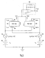
- Figures 2 and 3 show electromechanical schematic block diagrams of a MEMS gyroscope having two sense capacitors.
- the static equilibrium position of the proof mass is unchanged from its value with no applied voltage.
- the static equilibrium position of the proof mass shifts when voltage is applied.
- the use of two sense capacitors on each proof mass offers performance advantages due to the increased symmetry.
- fabricating only one sense capacitor on each proof mass frequently has the advantage of lower fabrication cost. Performance improvements obtained with the present invention are applicable regardless of the static equilibrium position of the proof mass.
- the electrostatic force in the single sense capacitor embodiment is not large enough to pull the proof mass against a sense electrode.
- two mechanically coupled proof masses 210 and 220 are driven in opposite directions by a Coriolis input force, or by a quadrature force originating from the applied motor force on the gyroscope.
- two capacitors comprising electrodes C left+ 244 and C left- 246, are positioned either side of proof mass 210, which also serves as an electrode between the left plus and minus electrodes.
- the electrodes are driven by DC voltage sources 225 and 230, and AC pump voltage sources 235 and 240.
- Current, I left sensed from the proof mass electrode is provided to an output circuit 250.
- Proof mass 220 also serve as an electrode between electrodes C right- 254 and C right+ 256. These electrodes are also driven by the DC and AC sources, but 180 degrees out of phase from proof mass 210. Current, I right , sensed from proof mass electrode 254 is summed with I left and provided to the output circuit 250.
- Figure 2 is an electromechanical schematic block diagram of a MEMS gyroscope with dc bias and ac pump voltage applied to the sense capacitors of the two proof masses.
- the two proof masses are mechanically coupled together and mechanically coupled to the substrate, though this mechanical coupling is not shown.
- the electronic charge pre-amplifier is also shown.
- Figure 3 is a simplified model of the MEMS gyroscope of Figure 2 , and is used as a model for a detailed calculation of the output signal from a MEMS gyroscope having parametric gain. Numbering in Figure 3 is consistent with that of Figure 2 , with proof mass 210 being shown. In addition, a spring constant 310 is represented as k o .
- Figure 3 shows one of the two proof masses depicted in Figure 2 , with its two sense electrodes.
- the sense electrodes in the model of Figure 3 are biased by dc bias voltages ⁇ V b and an ac pump signal ⁇ V p cos(2 ⁇ t + ⁇ ), where ⁇ is the frequency at which the gyroscope is driven electrostatically (the motor mode), and ⁇ is the phase angle of the pump voltage. It is important that the frequency of the pump signal be twice that of the driven motor motion.
- the output current of the model in Figure 3 will be half of the output current of the model in Figure 2 . In all other respects, the two models are equivalent.
- the sense electrodes 244 and 246 each comprise a plurality of fingers.
- the proof mass 210 also has a plurality of electrode fingers extending from the proof mass toward the substrate.
- a finger from each of the sense electrodes 244 and 246 having positive and negative polarities are disposed between two adjacent proof mass fingers such that the oscillating source voltages alternately draws the proof mass toward and away from the sense electrode fingers as is known in the art.
- the sense electrodes comprise parallel plates positioned above and below the proof mass, also as is known in the art.
- FIG 3 is a simplified model of the MEMS gyroscope shown in Figure 2 .
- the gyroscope output signal depends on the product of the mechanical gain and electrical gain. The mechanical gain will be calculated first, followed by the electrical gain.
- Equation (1) For the displacement y(t) of the proof mass.
- C + and C. are the two sense capacitances on opposite sides of the proof mass
- y is the displacement of the proof mass
- ⁇ is the damping constant for the sense mode.
- the rightmost term in equation (1) represents the electrostatic forces on the proof mass due to the applied voltages on the sense electrodes.
- ⁇ is chosen to be close to the sense mode resonant frequency ⁇ s .
- the term in y(t) at frequency ⁇ is much larger than the higher harmonic terms, and the higher harmonic terms can be neglected.
- Equation (5) The damping term is neglected in equation (5), because the separation between the sense and motor frequencies is typically chosen to be large enough that the damping term is negligible.
- the first term in equation (5) proportional to cos( ⁇ t + ⁇ ), shows that both the dc and ac applied voltages contribute to a shift in the sense resonant frequency due to electrostatic spring softening.
- Equation (5) is solved for y 1 and ⁇ , and such that the solutions are valid for all time t. Evaluating equation (5) at two values of ⁇ t differing by ⁇ /2 gives two independent equations that can be solved for the two unknowns y 1 and ⁇ .
- Table 1 shows that the amplitude y 1 of the mechanical response of the gyroscope depends on the phase ⁇ of the pump voltage and the phase ⁇ of the input force.
- ⁇ 0
- a practical MEMS gyroscope should avoid this instability.
- the practical ratio of Coriolis mechanical gain to quadrature mechanical gain will be limited, since this ratio becomes very large only if A is comparable to -B.
- Equation (13) shows that the electrical gain depends on the phase ⁇ of the pump voltage.
- the gyroscope is designed so that the quadrature signal is nulled.
- the gyroscope is designed to achieve high gain for the Coriolis signal, so that the output signal-to-noise ratio is dominated by thermal Brownian motion noise in the proof mass rather than the noise in the readout electronics.
- Table 2 shows the design parameters for a MEMS gyroscope that achieves null quadrature output current at a pump voltage of 10 V, without instability.
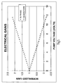
- Figures 4 , 5 , and 6 show the mechanical gain, electrical gain, and total gain for this design, as functions of the pump voltage.
- Figure 6 clearly shows a reduction of scale factor as the pump voltage is increased (scale factor is proportional to total gain of the Coriolis signal).
- this is a small price to pay for achieving complete nulling of the quadrature signal without complex electronic circuitry.
- Figure 4 is a graph of the Coriolis (in-phase) and quadrature mechanical gains for the design parameters of Table 2, as functions of the pump voltage.
- Figure 5 is a graph of the Coriolis (in-phase) and quadrature electrical gains for the design parameters of Table 2, as functions of the pump voltage.
- Figure 6 is a graph of the total Coriolis (in-phase) and quadrature gains for the design parameters of Table 2, as functions of the pump voltage. The total gain is calculated by multiplying the mechanical and electrical gain of Figures 4 and 5 .
- Design for high Coriolis signal gain The sensitivity of many MEMS gyroscopes is limited by noise in the readout electronics. One way to move closer to the fundamental limit of thermal mechanical noise limited sensitivity is to increase the gain of the sensor itself. This can be achieved by proper choice of the pump voltage and phase.
- Table 3 shows the design parameters for a MEMS gyroscope designed for high Coriolis signal gain at pump voltages approaching the instability at a pump voltage of about 7 V. This design is nearly the same as the design in Table 2, except that the sense frequency is above the motor frequency, so that electrostatic spring softening moves the sense and motor frequencies closer together. This increases the mechanical gain, but the gyroscope becomes more unstable.
- Figures 7 , 8 and 9 show the mechanical gain, electrical gain, and total gain as functions of the pump voltage for this design. These two designs are representative of just two of the potential designs that are within the invention as claimed. Many of the parameters may be varied without departing from the scope of the invention as is readily apparent to one skilled in the art. In some instances, instability may be desired. For example, the instability could provide an electromechanical oscillator. Table 3. Operating parameters for a MEMS gyroscope with high Coriolis signal gain near the instability at a pump voltage of about 7 V. The derivatives of sense capacitance with respect to proof mass displacement are calculated assuming parallel plate capacitors.
- Figure 7 is a graph of the Coriolis (in-phase) and quadrature mechanical gains for the design parameters of Table 3, as functions of the pump voltage.
- Figure 8 is a graph of the Coriolis (in-phase) and quadrature electrical gains for the design parameters of Table 3, as functions of the pump voltage.
- Figure 9 is a graph of the total Coriolis (in-phase) and quadrature gains for the design parameters of Table 3, as functions of the pump voltage. The total gain is calculated by multiplying the mechanical and electrical gain of Figures 7 and 8 .
Landscapes
- Physics & Mathematics (AREA)
- Engineering & Computer Science (AREA)
- General Physics & Mathematics (AREA)
- Radar, Positioning & Navigation (AREA)
- Remote Sensing (AREA)
- Gyroscopes (AREA)
- Pressure Sensors (AREA)
Claims (10)
- Gyroscope microélectromécanique (100) comprenant :une masse d'inertie (110, 224),un entraînement motorisé (160) qui fait osciller la masse d'inertie à sa fréquence de résonance dans un mode d'entraînement en oscillation,une électrode de détection (130) placée à côté de la masse d'inertie pour détecter l'oscillation de la masse d'inertie dans un mode de détection d'oscillation etune pompe (160) reliée à l'électrode de détection (130) et délivrant une force à deux fois la fréquence de résonance du mode d'entraînement en oscillation.
- Gyroscope microélectromécanique selon la revendication 1, comprenant de plus un circuit de sortie (250) qui présente une rétroaction résistive et capacitive parallèle.
- Gyroscope microélectromécanique selon la revendication 1, dont la pompe (160) est agencée de telle sorte que la force délivrée par la pompe est induite par un signal électrique qui présente une composante de courant continu (225) et une composante de courant alternatif (235), la tension électrique de la composante de courant alternatif représentant approximativement deux fois la tension électrique de la composante de courant continu.
- Gyroscope microélectromécanique selon la revendication 1, dont la masse d'inertie est suspendue à un substrat par des ressorts (120).
- Gyroscope microélectromécanique selon la revendication 4, dont le substrat est constitué de silice ou de pyrex.
- Gyroscope microélectromécanique selon la revendication 1, dont l'entraînement motorisé (160) est agencé de telle sorte que la fréquence du mode d'entraînement en oscillation est supérieure à la fréquence du mode de détection de l'oscillation.
- Procédé de mesure de la force de Coriolis, le procédé comprenant les étapes qui consistent à
faire osciller une masse d'inertie (110, 244) à sa fréquence de résonance dans un mode d'entraînement en oscillation,
délivrer une force de pompage (160) en mode de détection de l'oscillation de la masse d'inertie à approximativement deux fois la fréquence de résonance, la force de pompage étant essentiellement perpendiculaire au mode d'entraînement en oscillation et
dans le mode de détection de l'oscillation, détecter l'oscillation de la masse d'inertie induite par la force de Coriolis. - Procédé selon la revendication 7, comprenant de plus l'étape qui consiste à transmettre l'oscillation détectée à un circuit de sortie relié à la masse d'inertie.
- Procédé selon la revendication 7, dans lequel la force délivrée par la pompe est induite par un signal électrique qui présente une composante de courant continu et une composante de courant alternatif, la tension électrique de la composante de courant alternatif représentant approximativement deux fois la tension électrique de la composante de courant continu.
- Procédé selon la revendication 7, dans lequel la masse d'inertie est constituée de silice et est suspendue à un substrat par des ressorts.
Applications Claiming Priority (3)
| Application Number | Priority Date | Filing Date | Title |
|---|---|---|---|
| US10/132,056 US6715353B2 (en) | 2002-04-25 | 2002-04-25 | MEMS gyroscope with parametric gain |
| US132056 | 2002-04-25 | ||
| PCT/US2003/012529 WO2004038330A2 (fr) | 2002-04-25 | 2003-04-23 | Gyroscope mems à gain paramétrique |
Publications (2)
| Publication Number | Publication Date |
|---|---|
| EP1497617A2 EP1497617A2 (fr) | 2005-01-19 |
| EP1497617B1 true EP1497617B1 (fr) | 2009-01-07 |
Family
ID=29248683
Family Applications (1)
| Application Number | Title | Priority Date | Filing Date |
|---|---|---|---|
| EP03799752A Expired - Lifetime EP1497617B1 (fr) | 2002-04-25 | 2003-04-23 | Gyroscope mems a gain parametrique |
Country Status (7)
| Country | Link |
|---|---|
| US (1) | US6715353B2 (fr) |
| EP (1) | EP1497617B1 (fr) |
| JP (1) | JP4365323B2 (fr) |
| AU (1) | AU2003299462B2 (fr) |
| CA (1) | CA2483710A1 (fr) |
| DE (1) | DE60325714D1 (fr) |
| WO (1) | WO2004038330A2 (fr) |
Cited By (1)
| Publication number | Priority date | Publication date | Assignee | Title |
|---|---|---|---|---|
| EP4650713A1 (fr) * | 2024-05-14 | 2025-11-19 | Atlantic Inertial Systems Limited | Capteur gyroscopique capacitif |
Families Citing this family (37)
| Publication number | Priority date | Publication date | Assignee | Title |
|---|---|---|---|---|
| US7036373B2 (en) | 2004-06-29 | 2006-05-02 | Honeywell International, Inc. | MEMS gyroscope with horizontally oriented drive electrodes |
| RU2274833C1 (ru) * | 2004-10-01 | 2006-04-20 | Федеральное государственное унитарное предприятие Центральный научно-исследовательский институт "Электроприбор" | Устройство преобразования сигналов микромеханического гироскопа вибрационного типа |
| JP4611005B2 (ja) * | 2004-11-30 | 2011-01-12 | パイオニア株式会社 | センサ素子 |
| US7485847B2 (en) | 2004-12-08 | 2009-02-03 | Georgia Tech Research Corporation | Displacement sensor employing discrete light pulse detection |
| US7401515B2 (en) * | 2006-03-28 | 2008-07-22 | Honeywell International Inc. | Adaptive circuits and methods for reducing vibration or shock induced errors in inertial sensors |
| US7444869B2 (en) * | 2006-06-29 | 2008-11-04 | Honeywell International Inc. | Force rebalancing and parametric amplification of MEMS inertial sensors |
| US7444868B2 (en) | 2006-06-29 | 2008-11-04 | Honeywell International Inc. | Force rebalancing for MEMS inertial sensors using time-varying voltages |
| US8037757B2 (en) | 2007-12-12 | 2011-10-18 | Honeywell International Inc. | Parametric amplification of a MEMS gyroscope by capacitance modulation |
| DE102008041757B4 (de) * | 2008-09-02 | 2019-01-03 | Robert Bosch Gmbh | Herstellungsverfahren für eine Rotationssensorvorrichtung und Rotationssensorvorrichtung |
| US8096179B2 (en) * | 2009-04-09 | 2012-01-17 | Freescale Semiconductor, Inc. | Sensor device with reduced parasitic-induced error |
| US8890941B2 (en) | 2010-04-29 | 2014-11-18 | Virginia Venture Industries, Llc | Methods and apparatuses for viewing three dimensional images |
| IL214294A0 (en) * | 2011-07-26 | 2011-09-27 | Rafael Advanced Defense Sys | Surface micro-machined switching device |
| US9714842B2 (en) * | 2011-09-16 | 2017-07-25 | Invensense, Inc. | Gyroscope self test by applying rotation on coriolis sense mass |
| US9863769B2 (en) | 2011-09-16 | 2018-01-09 | Invensense, Inc. | MEMS sensor with decoupled drive system |
| US10914584B2 (en) | 2011-09-16 | 2021-02-09 | Invensense, Inc. | Drive and sense balanced, semi-coupled 3-axis gyroscope |
| KR101371149B1 (ko) | 2012-01-18 | 2014-03-06 | 주식회사 에스알파워 | 멤즈 기반의 자이로스코프 |
| US9310202B2 (en) * | 2012-07-09 | 2016-04-12 | Freescale Semiconductor, Inc. | Angular rate sensor with quadrature error compensation |
| CN103047978B (zh) * | 2012-12-17 | 2013-11-13 | 北京信息科技大学 | 一种钟形振子式角速率陀螺谐振子频率裂解抑制方法 |
| US9341646B2 (en) * | 2012-12-19 | 2016-05-17 | Northrop Grumman Guidance And Electronics Company, Inc. | Bias reduction in force rebalanced accelerometers |
| US9534896B2 (en) | 2013-03-27 | 2017-01-03 | Honeywell International Inc. | Oscillating voltage of sense electrodes in a MEMS tuning fork gyroscope |
| DE102013208822A1 (de) * | 2013-05-14 | 2014-11-20 | Robert Bosch Gmbh | Verfahren zum Betrieb eines Drehratensensors |
| US10273147B2 (en) | 2013-07-08 | 2019-04-30 | Motion Engine Inc. | MEMS components and method of wafer-level manufacturing thereof |
| WO2015013827A1 (fr) * | 2013-08-02 | 2015-02-05 | Motion Engine Inc. | Capteur de mouvement à système microélectromécanique (mems) pour détection de vitesse angulaire de sous-résonance |
| DE102013215587A1 (de) * | 2013-08-07 | 2015-02-12 | Robert Bosch Gmbh | Verfahren und Vorrichtung zum Einstellen des Dynamikbereichs eines Drehratensensors |
| FI127287B (en) | 2013-11-01 | 2018-03-15 | Murata Manufacturing Co | Microelectromechanical sensor device with improved quadrature compensation |
| WO2015103688A1 (fr) | 2014-01-09 | 2015-07-16 | Motion Engine Inc. | Système mems intégré |
| US9958271B2 (en) | 2014-01-21 | 2018-05-01 | Invensense, Inc. | Configuration to reduce non-linear motion |
| US20170030788A1 (en) | 2014-04-10 | 2017-02-02 | Motion Engine Inc. | Mems pressure sensor |
| US11674803B2 (en) | 2014-06-02 | 2023-06-13 | Motion Engine, Inc. | Multi-mass MEMS motion sensor |
| CN106461394A (zh) | 2014-06-26 | 2017-02-22 | 路梅戴尼科技公司 | 用于从非线性周期信号确定旋转的系统和方法 |
| US9581447B2 (en) * | 2014-07-08 | 2017-02-28 | Honeywell International Inc. | MEMS gyro motor loop filter |
| US11287486B2 (en) | 2014-12-09 | 2022-03-29 | Motion Engine, Inc. | 3D MEMS magnetometer and associated methods |
| US10407299B2 (en) | 2015-01-15 | 2019-09-10 | Motion Engine Inc. | 3D MEMS device with hermetic cavity |
| TWI650558B (zh) | 2015-05-20 | 2019-02-11 | 美商路梅戴尼科技公司 | 用於決定慣性參數之方法及系統 |
| US10877063B2 (en) * | 2015-12-10 | 2020-12-29 | Invensense, Inc. | MEMS sensor with compensation of residual voltage |
| US10234477B2 (en) | 2016-07-27 | 2019-03-19 | Google Llc | Composite vibratory in-plane accelerometer |
| IT201900009582A1 (it) * | 2019-06-20 | 2020-12-20 | St Microelectronics Srl | Giroscopio mems con calibrazione del fattore di scala in tempo reale e relativo metodo di calibrazione |
Family Cites Families (6)
| Publication number | Priority date | Publication date | Assignee | Title |
|---|---|---|---|---|
| US5747961A (en) * | 1995-10-11 | 1998-05-05 | The Charles Stark Draper Laboratory, Inc. | Beat frequency motor position detection scheme for tuning fork gyroscope and other sensors |
| JPH09196682A (ja) * | 1996-01-19 | 1997-07-31 | Matsushita Electric Ind Co Ltd | 角速度センサと加速度センサ |
| US5992233A (en) * | 1996-05-31 | 1999-11-30 | The Regents Of The University Of California | Micromachined Z-axis vibratory rate gyroscope |
| US5911156A (en) | 1997-02-24 | 1999-06-08 | The Charles Stark Draper Laboratory, Inc. | Split electrode to minimize charge transients, motor amplitude mismatch errors, and sensitivity to vertical translation in tuning fork gyros and other devices |
| US6393913B1 (en) * | 2000-02-08 | 2002-05-28 | Sandia Corporation | Microelectromechanical dual-mass resonator structure |
| JP2001264072A (ja) * | 2000-03-17 | 2001-09-26 | Aisin Seiki Co Ltd | 角速度センサ |
-
2002
- 2002-04-25 US US10/132,056 patent/US6715353B2/en not_active Expired - Lifetime
-
2003
- 2003-04-23 DE DE60325714T patent/DE60325714D1/de not_active Expired - Lifetime
- 2003-04-23 CA CA002483710A patent/CA2483710A1/fr not_active Abandoned
- 2003-04-23 EP EP03799752A patent/EP1497617B1/fr not_active Expired - Lifetime
- 2003-04-23 AU AU2003299462A patent/AU2003299462B2/en not_active Ceased
- 2003-04-23 WO PCT/US2003/012529 patent/WO2004038330A2/fr not_active Ceased
- 2003-04-23 JP JP2004546656A patent/JP4365323B2/ja not_active Expired - Fee Related
Cited By (1)
| Publication number | Priority date | Publication date | Assignee | Title |
|---|---|---|---|---|
| EP4650713A1 (fr) * | 2024-05-14 | 2025-11-19 | Atlantic Inertial Systems Limited | Capteur gyroscopique capacitif |
Also Published As
| Publication number | Publication date |
|---|---|
| US20030200804A1 (en) | 2003-10-30 |
| WO2004038330A2 (fr) | 2004-05-06 |
| DE60325714D1 (de) | 2009-02-26 |
| EP1497617A2 (fr) | 2005-01-19 |
| AU2003299462B2 (en) | 2006-03-30 |
| AU2003299462A1 (en) | 2004-05-13 |
| JP2006501483A (ja) | 2006-01-12 |
| WO2004038330A3 (fr) | 2004-07-29 |
| US6715353B2 (en) | 2004-04-06 |
| CA2483710A1 (fr) | 2004-05-06 |
| JP4365323B2 (ja) | 2009-11-18 |
Similar Documents
| Publication | Publication Date | Title |
|---|---|---|
| EP1497617B1 (fr) | Gyroscope mems a gain parametrique | |
| KR100393183B1 (ko) | 마이크로액츄에이터의상보형정전구동장치 | |
| US7036373B2 (en) | MEMS gyroscope with horizontally oriented drive electrodes | |
| US6230563B1 (en) | Dual-mass vibratory rate gyroscope with suppressed translational acceleration response and quadrature-error correction capability | |
| EP2071284B1 (fr) | Amplification paramétrique d'un gyroscope MEMS par modulation de la capacité | |
| JP4458441B2 (ja) | 分割電極を有する音叉ジャイロ | |
| US8056413B2 (en) | Sensor and sensing method utilizing symmetrical differential readout | |
| EP1603830B1 (fr) | Accelerometre | |
| US6621279B2 (en) | Drive feedthrough nulling system | |
| JP2005504273A (ja) | ピックオフ共振減衰が大きくなった超小型機械慣性センサ | |
| EP2236982B1 (fr) | Réduction de la sensibilité au gradient du champ magnétique de gyroscope MEMS | |
| JP2012108148A (ja) | 音叉ジャイロスコープ、加速度計、および改善されたスケール係数を有する他の検出器 | |
| CN101135560A (zh) | 双线振动硅微陀螺仪 | |
| KR101433590B1 (ko) | 커패시턴스 변조에 의한 mems 자이로스코프의 파라미터증폭 | |
| US20240400380A1 (en) | Microelectromechanical gyroscope with improved vibration rejection | |
| JPH07128356A (ja) | 2軸角速度/加速度センサ | |
| Gadola et al. | Navigation-grade NEMS gyroscopes |
Legal Events
| Date | Code | Title | Description |
|---|---|---|---|
| PUAI | Public reference made under article 153(3) epc to a published international application that has entered the european phase |
Free format text: ORIGINAL CODE: 0009012 |
|
| 17P | Request for examination filed |
Effective date: 20041026 |
|
| AK | Designated contracting states |
Kind code of ref document: A2 Designated state(s): AT BE BG CH CY CZ DE DK EE ES FI FR GB GR HU IE IT LI LU MC NL PT RO SE SI SK TR |
|
| AX | Request for extension of the european patent |
Extension state: AL LT LV MK |
|
| GRAP | Despatch of communication of intention to grant a patent |
Free format text: ORIGINAL CODE: EPIDOSNIGR1 |
|
| GRAS | Grant fee paid |
Free format text: ORIGINAL CODE: EPIDOSNIGR3 |
|
| GRAA | (expected) grant |
Free format text: ORIGINAL CODE: 0009210 |
|
| AK | Designated contracting states |
Kind code of ref document: B1 Designated state(s): DE FR GB IT |
|
| REG | Reference to a national code |
Ref country code: GB Ref legal event code: FG4D |
|
| REF | Corresponds to: |
Ref document number: 60325714 Country of ref document: DE Date of ref document: 20090226 Kind code of ref document: P |
|
| PLBE | No opposition filed within time limit |
Free format text: ORIGINAL CODE: 0009261 |
|
| STAA | Information on the status of an ep patent application or granted ep patent |
Free format text: STATUS: NO OPPOSITION FILED WITHIN TIME LIMIT |
|
| 26N | No opposition filed |
Effective date: 20091008 |
|
| PG25 | Lapsed in a contracting state [announced via postgrant information from national office to epo] |
Ref country code: IT Free format text: LAPSE BECAUSE OF FAILURE TO SUBMIT A TRANSLATION OF THE DESCRIPTION OR TO PAY THE FEE WITHIN THE PRESCRIBED TIME-LIMIT Effective date: 20090107 |
|
| REG | Reference to a national code |
Ref country code: FR Ref legal event code: PLFP Year of fee payment: 14 |
|
| REG | Reference to a national code |
Ref country code: FR Ref legal event code: PLFP Year of fee payment: 15 |
|
| REG | Reference to a national code |
Ref country code: FR Ref legal event code: PLFP Year of fee payment: 16 |
|
| PGFP | Annual fee paid to national office [announced via postgrant information from national office to epo] |
Ref country code: IT Payment date: 20180823 Year of fee payment: 15 |
|
| REG | Reference to a national code |
Ref country code: DE Ref legal event code: R119 Ref document number: 60325714 Country of ref document: DE |
|
| PG25 | Lapsed in a contracting state [announced via postgrant information from national office to epo] |
Ref country code: DE Free format text: LAPSE BECAUSE OF NON-PAYMENT OF DUE FEES Effective date: 20191101 |
|
| PGFP | Annual fee paid to national office [announced via postgrant information from national office to epo] |
Ref country code: GB Payment date: 20220419 Year of fee payment: 20 Ref country code: FR Payment date: 20220427 Year of fee payment: 20 |
|
| REG | Reference to a national code |
Ref country code: GB Ref legal event code: PE20 Expiry date: 20230422 |
|
| P01 | Opt-out of the competence of the unified patent court (upc) registered |
Effective date: 20230525 |
|
| PG25 | Lapsed in a contracting state [announced via postgrant information from national office to epo] |
Ref country code: GB Free format text: LAPSE BECAUSE OF EXPIRATION OF PROTECTION Effective date: 20230422 |