EP1497620B1 - Magnetischer wegsensor - Google Patents
Magnetischer wegsensor Download PDFInfo
- Publication number
- EP1497620B1 EP1497620B1 EP03727370A EP03727370A EP1497620B1 EP 1497620 B1 EP1497620 B1 EP 1497620B1 EP 03727370 A EP03727370 A EP 03727370A EP 03727370 A EP03727370 A EP 03727370A EP 1497620 B1 EP1497620 B1 EP 1497620B1
- Authority
- EP
- European Patent Office
- Prior art keywords
- devices
- transducer
- sensing devices
- oriented
- axis
- Prior art date
- Legal status (The legal status is an assumption and is not a legal conclusion. Google has not performed a legal analysis and makes no representation as to the accuracy of the status listed.)
- Expired - Lifetime
Links
- 230000005291 magnetic effect Effects 0.000 title claims abstract description 125
- 238000006073 displacement reaction Methods 0.000 title claims abstract description 34
- 230000001419 dependent effect Effects 0.000 claims abstract description 7
- 239000000654 additive Substances 0.000 claims description 23
- 230000000996 additive effect Effects 0.000 claims description 23
- 239000003302 ferromagnetic material Substances 0.000 claims description 14
- 238000009738 saturating Methods 0.000 claims description 11
- 238000012545 processing Methods 0.000 claims description 3
- 230000003750 conditioning effect Effects 0.000 claims 1
- 230000004044 response Effects 0.000 description 93
- 230000035945 sensitivity Effects 0.000 description 14
- 238000012546 transfer Methods 0.000 description 14
- 230000007246 mechanism Effects 0.000 description 13
- 239000000463 material Substances 0.000 description 8
- 238000005259 measurement Methods 0.000 description 8
- 230000004907 flux Effects 0.000 description 7
- 238000005516 engineering process Methods 0.000 description 4
- 230000008901 benefit Effects 0.000 description 3
- 238000000926 separation method Methods 0.000 description 3
- 230000005355 Hall effect Effects 0.000 description 2
- XEEYBQQBJWHFJM-UHFFFAOYSA-N Iron Chemical compound [Fe] XEEYBQQBJWHFJM-UHFFFAOYSA-N 0.000 description 2
- 230000004323 axial length Effects 0.000 description 2
- 238000011161 development Methods 0.000 description 2
- 230000018109 developmental process Effects 0.000 description 2
- 230000000694 effects Effects 0.000 description 2
- 239000012466 permeate Substances 0.000 description 2
- 230000000750 progressive effect Effects 0.000 description 2
- 239000013598 vector Substances 0.000 description 2
- 229910000975 Carbon steel Inorganic materials 0.000 description 1
- 229910000831 Steel Inorganic materials 0.000 description 1
- 239000000853 adhesive Substances 0.000 description 1
- 230000001070 adhesive effect Effects 0.000 description 1
- 239000004411 aluminium Substances 0.000 description 1
- XAGFODPZIPBFFR-UHFFFAOYSA-N aluminium Chemical compound [Al] XAGFODPZIPBFFR-UHFFFAOYSA-N 0.000 description 1
- 229910052782 aluminium Inorganic materials 0.000 description 1
- 230000003321 amplification Effects 0.000 description 1
- 230000000712 assembly Effects 0.000 description 1
- 238000000429 assembly Methods 0.000 description 1
- 230000009286 beneficial effect Effects 0.000 description 1
- 230000008859 change Effects 0.000 description 1
- 238000006243 chemical reaction Methods 0.000 description 1
- 150000001875 compounds Chemical class 0.000 description 1
- 238000005094 computer simulation Methods 0.000 description 1
- 230000005294 ferromagnetic effect Effects 0.000 description 1
- 238000009434 installation Methods 0.000 description 1
- 229910052742 iron Inorganic materials 0.000 description 1
- 238000003475 lamination Methods 0.000 description 1
- 238000012886 linear function Methods 0.000 description 1
- 239000000696 magnetic material Substances 0.000 description 1
- 230000003121 nonmonotonic effect Effects 0.000 description 1
- 238000003199 nucleic acid amplification method Methods 0.000 description 1
- 230000003287 optical effect Effects 0.000 description 1
- 229910000889 permalloy Inorganic materials 0.000 description 1
- 238000007747 plating Methods 0.000 description 1
- 230000009467 reduction Effects 0.000 description 1
- 239000010959 steel Substances 0.000 description 1
- 230000009897 systematic effect Effects 0.000 description 1
- 238000012360 testing method Methods 0.000 description 1
- 229910000859 α-Fe Inorganic materials 0.000 description 1
Images






Classifications
-
- G—PHYSICS
- G01—MEASURING; TESTING
- G01D—MEASURING NOT SPECIALLY ADAPTED FOR A SPECIFIC VARIABLE; ARRANGEMENTS FOR MEASURING TWO OR MORE VARIABLES NOT COVERED IN A SINGLE OTHER SUBCLASS; TARIFF METERING APPARATUS; MEASURING OR TESTING NOT OTHERWISE PROVIDED FOR
- G01D5/00—Mechanical means for transferring the output of a sensing member; Means for converting the output of a sensing member to another variable where the form or nature of the sensing member does not constrain the means for converting; Transducers not specially adapted for a specific variable
- G01D5/12—Mechanical means for transferring the output of a sensing member; Means for converting the output of a sensing member to another variable where the form or nature of the sensing member does not constrain the means for converting; Transducers not specially adapted for a specific variable using electric or magnetic means
- G01D5/14—Mechanical means for transferring the output of a sensing member; Means for converting the output of a sensing member to another variable where the form or nature of the sensing member does not constrain the means for converting; Transducers not specially adapted for a specific variable using electric or magnetic means influencing the magnitude of a current or voltage
Definitions
- This invention relates to a displacement measurement transducer, particularly for linear displacement or position measurement.
- the invention has been developed in relation to measuring the linear movement of a clutch mounted on a gear shaft housing.
- the invention is considered to have more general utility.
- the invention utilises magnetic transducer technology.
- the gear shaft housing is of a ferromagnetic material and that the transducer has to "see through” the material of the housing with a magnetic source positioned on one side and a magnetic detector positioned on the other.
- the magnetic source will be described in terms of one or more permanent magnets. It will be understood that electromagnets may also be used.
- the magnetic detector will be described in terms of one or more sensor devices. Suitable devices include the magnetoresistive, Hall effect and saturating core (inductor) type.
- the present invention has been implemented in a signal conditioner and processing circuit (SCSP) of the kind described in published PCT application WO98/52063 . In such an SCSP circuit plural sensor devices of the saturating core type can be connected in additive (summing) or subtractive (differential) fashion.
- a sensor provides a voltage signal proportional to the tool chuck opening width.
- Said sensor cooperates with e.g. a cylindrical magnetic ring, adopting a position dependency on the chuck opening width.
- a first aspect of the invention addresses the problem set forth above. Further aspects of the present invention are directed to further developments of the technology described in connection with the first aspect of the invention with particular attention being given to transducer configurations providing a linear transfer function between a displacement-representing output and the displacement being measured. As has already been indicated magnetic displacement transducers embodying the invention are of general utility.
- a transducer of the present invention for measuring a displacement along an axis of movement of a first part relative to a second part comprises a magnetic source for generating a magnetic field mounted to the first part, a plurality of magnetic field sensing devices mounted to the second part to be movable relative to the magnetic field generated by the magnetic source, said plurality of sensing devices being spaced in the direction of said axis, and a circuit arrangement to which said plurality of sensing devices are connected to generate an output signal dependent on contributions from the sensing devices of the plurality, wherein said magnetic source has North and South poles oriented in the direction of said axis, the sensing devices of said plurality are each oriented to respond to an axially-directed component of magnetic field, and the plurality comprises at least two axially-spaced sensing devices whose contributions to the output signal are combined in a subtractive fashion, characterized in that an intervening ferromagnetic material is arranged between said magnetic source and said plurality of magnetic field sensing devices
- the sensing devices of said plurality are each oriented to respond to a radially-oriented component of said magnetic field with respect to the direction of said axis, and the plurality comprises at least two axially-spaced sensing devices whose contributions are combined in an additive fashion.
- said magnetic source has North and South poles oriented radially with respect to said axis, and the plurality comprises at least two axially-spaced sensing devices whose contributions are combined in an additive fashion.
- said magnetic source has North and South poles oriented radially with respect to said axis, and the sensing devices of said plurality are each oriented to respond to a radially-directed component of said magnetic field, and the plurality comprises at least two axially-spaced sensing devices whose contributions are combined in a subtractive fashion.
- said magnetic source has North and South poles oriented in a given direction with respect to said axis, the sensing devices of said plurality are each oriented to respond to a component of said magnetic field in said given direction, and the plurality comprises at least two devices whose contributions are combined in a subtractive fashion.
- said magnetic source has North and South poles oriented in a given direction with respect to said axis, the sensing devices of said plurality are each oriented to respond to a component of said magnetic field normal to said given direction, and the plurality comprises at least two devices whose contributions are combined in an additive fashion.
- At least one magnetic source is mounted to the first part and at least one magnetic field sensor mounted to the second part to be movable relative to the magnetic field generated by the source, said at least one magnetic detector being connected in a circuit producing an output signal which is a function of the relative position of the first and second parts, wherein, one of said at least one magnetic source and said at least one magnetic field sensor comprises two devices spaced in the direction of relative movement such that said output signal is a monotonic function of the relative position of the first and second parts over a range of displacement.
- Fig. 1 shows in an exploded view elements of a transducer of the invention applied to a clutch mechanism and in which an arrangement of magnetic source and magnetic field sensor devices is shown diagrammatically.
- a tube 10 for example the housing of a gear shaft, has a clutch mechanism 20 slidably mounted on it for movement in the axial direction A-A of the tube, that is the mechanism is mounted for linear movement.
- the clutch mechanism carries a permanent magnet or assembly of magnets 30.
- Magnet 30 is located within the mechanism 20 which will normally have a magnetically permeable housing, as of aluminium.
- Fitted within the tube is a holder 40 for one or more sensing coils 50 which are located off-axis adjacent the wall of the tube 10 to which the magnet 30 is proximate. It will be understood that the sensor holder 40 is mounted within the tube 10 with the clutch mechanism 20 encircling the tube. Figs.
- FIGS. 2a and 2b show the assembly with the clutch mechanism 20 in different axial positions measurable by an auxiliary measuring device 60 fixed with respect to tube 10 to provide a reference measurement of the axial position of mechanism 20 in the test rig.
- the mechanism is movable in the direction A-A by say ⁇ 30 mm.
- the transducer is designed to provide an output signal which is a measure of this axial displacement and an important factor which then arises is the linearity of the transducer transfer function.
- the magnet 30 is mounted at say 1.7 mm from the outer surface of tube 10.
- the sensor devices 50 are mounted to be in contact with or very closely adjacent the inner surface of tube 10.
- the tube is of a ferromagnetic material, e.g. steel. It has been found that sufficient field will penetrate through the tube but satisfactory operation requires the magnetic source and detector to be placed closely adjacent on opposite sides of the tube wall.
- the ferromagnetic material should have a low remanence to avoid the establishment of region(s) of permanent magnetisation in the tube.
- the sensor device(s) 50 are connected into an SCSP circuit (not shown) for obtaining a signal dependent on the detected field strength and, more particularly, a signal which utilises the field gradient as a function of axial position.
- the output obtained is a function of both the field pattern as a function of axial distance - that is the field pattern relative to a datum fixed for the source (e.g. assume the mechanism 20 is stationary) - and the response pattern of the detector - that is the sensitivity of the detector as a function of axial position relative to a fixed datum for the sensor.
- This response pattern is also dependent on the orientation of the sensor device(s) and on their dimensions which affects the resolution of a given device.
- Typically saturating core sensors have a maximum sensitivity along the axis of the inductor and a physical length of about 6 mm.
- the source field pattern is also dependent on the orientation of the permanent magnet(s) and upon magnet dimensions.
- Non-linear functions can be used by calibration of the transducer, e.g. by computer processing using a look-up table or defined conversion equation. Non-monotonic functions should be avoided.
- Fig. 3 illustrates a longitudinal section through a tube 10 externally of which a magnet 30 is mounted, say 30 x 10 x 3 mm in dimension (length by width x depth).
- the magnet is mounted parallel to the axis of displacement (axially oriented).
- Within the tube at least one, and preferably a plurality of sensor devices 51, 52, 53 etc. are mounted. They are axially oriented (maximum axis of sensitivity in the direction of relative movement A-A) and are axially spaced. Two such devices can be connected in differential fashion into a single SCSP to obtain a linearised response. Other arrangements may use additively connected devices or combinations of additively connected devices.
- Transducers are obtainable using a radially-oriented magnet and axially-oriented sensor devices as shown in Fig. 4 or vice versa. Where radially-oriented sensor devices are used they are still spaced in the axial direction.
- Fig. 5 One arrangement of sensor devices is shown in Fig. 5 in which six axially-oriented devices are used in two groups 54a, 54b all three with a spacing D between the groups that is greater than the device spacing with each group. All the devices are connected additively into one SCSP circuits.
- the magnets employed may be of arcuate form to fit a tube.
- the application of the transducer has been described in relation to a three-dimensional, circular cross-section embodiment, the teachings herein can be applied to essentially planar systems. It is not necessary to have any intervening component between the magnetic source and detector. They could be arranged for relative displacement in air or other ambient medium.
- a ferromagnetic material is disposed between said at least one magnetic source and said at least one magnetic field sensor and the source(s) and sensor(s) are mounted in close proximity on opposite sides of the ferromagnetic material.
- the second aspect of the present invention is concerned with further developments in relation to configurations of magnetic source(s) and magnetic sensor device(s) which demonstrate a linear response characteristic.
- the invention is also concerned with a magnetic source structure for controlling the magnetic flux to which the sensor device(s) react.
- the present invention enables useful linear responses to be developed for a range of displacement. Particular consideration is given to the following magnetic source and magnetic field sensor combinations with respect to an axis of relative movement:
- Basic responses relate to the response of a single sensor device.
- the hump type basic responses can be transformed or converted to a response having a linear slope portion when using a plurality of sensors the combining of the contributions of which includes a subtraction (difference) function.
- the linear slope portion basic responses can be enhanced by additively combining the contributions of a plurality of sensors.
- transducers in which a magnet is used in combination with a plurality of sensor devices.
- What will be discussed below is a systematic way of creating a desired transfer function, and particularly a transfer function which has a linear characteristic over a large range of displacement. Potentially desirable characteristics can be developed and explored using computer simulation or modelling which has the benefit of enabling the effect of variation of parameters to be readily investigated. More specifically, the overall transfer function of a combination of one or more magnets with one or more sensor devices can be investigated from the initial stand point of the field distribution due to a single magnet and the response characteristic of a single sensor device.
- the above four configurations are not exhaustive but represent the most likely orientations of magnets and sensor devices.
- the transducer configurations specifically described below are for a single magnet used in combination with a plurality of sensors.
- the devices will be taken to be of the saturating core type and connected in series to a single SCSP circuit of the kind disclosed in WO98/52063 .
- SCSP single SCSP circuit of the kind disclosed in WO98/52063 .
- a magnet whose length between the poles is large compared with the cross-section dimensions may be conveniently referred to as having a high aspect ratio: conversely a magnet whose length between the poles is small relative to its cross-section dimensions has a low aspect ratio.
- the sensor devices are of the saturating core type, they can be connected in series into an SCSP circuit, the polarity of the connection determining whether the result is additive or subtractive (sum or difference connection).
- the material b e a soft magnetic material with low remanent flux density and low hysteresis and thus low coercivity.
- Materials that meet this requirement include pure iron, Mumetal and Permalloy, together with simple low carbon steels or material used for transformer core laminations having a mainly ferrite grain structure.
- the choice of the intervening material may be determined by mechanical properties related to practical engineering requirements.
- the thickness of the intervening material separating the source(s) from the sensor(s) is also relevant.
- the magnetic field or flux distribution detected by a sensor has a local vector direction associated as is well known for plots of the magnetic flux lines in the vicinity of a magnet. Furthermore, the local vectors may vary with the dimension of the magnet.
- Saturating core sensors normally comprise a coil wound solenoid-like on an axially-extending core. The sensitivity can be selected by selection of the number of coil turns.
- an advantage of saturating core sensors is that a plurality of sensors can be connected (in series) into a single SCSP circuit in additive or/and subtractive fashion.
- sensors can be connected into separate SCSP circuits if required or preferred and the outputs of the individual circuits combined in the required manner in an overall circuit arrangement from which a desired displacement (position)-representing signal is obtained.
- FIGs. 6a and 6b these figures illustrate another measure that can be taken to adjust the value of magnetic field to which a sensor device or devices responds.
- the figures show a tube 10' of circular cross-section outwardly of which is mounted a magnet 30'. Within the tube, part 40' is mounted to be movable in the axial direction A-A relative to tube 10'. Mounted to the part 40' is a magnetic sensor device assembly 50', the axis of maximum sensitivity of each individual device being axially-directed.
- the magnet 30' is a permanent magnet having its poles N-S oriented in the axial direction, but it has an arcuate shape in the circumferential direction about axis A-A. This is of benefit where the movement of the part 40' relative to tube 10' may entail angular displacement between the magnetic source 30' and the sensor assembly 50', or even allow for some degree of angular misalignment.
- the magnet of a given radius r may subtend an angle ⁇ of ⁇ 5° with respect to the position of sensor 90 assembly 50' about the axis.
- the arcuate magnet 30' is fixedly mounted relative to the tube 10'.
- the magnet is supported on an arcuate plate 60 of a ferromagnetic material, for example attached by an adhesive.
- the plate 60 may be inward of the magnet as shown or outward of the magnet. Because the plate 60 is of ferromagnetic material it will provide a shunt path for magnetic flux generated by the magnet which i n turn will affect the strength of the magnetic field which permeates the tube 10' to affect the sensor assembly 50'.
- the plate may be shaped to determine the reluctance of the shunt path which it provides.
- the plate 60 could be provided by appropriately plating the inner or outer surface of the arcuate magnet with a ferromagnetic material.
- the magnetic source comprises a single magnet
- the magnetic field detector comprises a single sensor device to demonstrate the basic response characteristic, and as is preferred, a plurality of sensor devices from which a combined transfer function is obtained.
- the transfer function can be expressed in a volts output per millimetre of displacement form (V/mm).
- V/mm volts output per millimetre of displacement form
- the tube wall or separator is denoted 10.
- the magnetic source comprises a magnet 30 or 30' for an axial or radial magnet respectively and the magnetic field detector assembly 50 comprises a single sensor device 50 or a plurality of sensor devices 51, 52 ... and so forth.
- the devices are axially-oriented in the direction of axis A-A unless marked with a prime indicating devices oriented normally to axis A-A, i.e. radially as illustrated.
- the axial direction is horizontal and is indicated by arrows A-A. It will be assumed that the tube and detector assembly is fixed and the magnet 30 or 30' is movable in the direction A-A to effect relative movement between the magnetic source and the detector assembly. In most applications it will be more practical to mount the magnet to a movable part while mounting the detector assembly of interconnected sensor devices to a fixed part.
- Fig. 7a shows a magnet 30 whose magnetic field permeates a separator wall 10 to be detected by an axially-oriented sensor device 50 connected into an SCSP circuit 70.
- the circuit 70 generates an output voltage proportional to the axial component of the magnetic field detected by device 50.
- the axially-oriented magnet 30 is of large aspect ratio with axially spaced poles N-S. Typically the magnet is of 12-20 mm length, 10 mm width and 3 mm depth.
- the axially-oriented sensor device 50 is a few millimetres long and typically about 2 mm diameter.
- Fig. 7b shows the output V of the circuit 70 in arbitrary voltage units on the ordinate axis as a function of the position x of the magnet 30 along the A-A axis of Fig. 7a .
- the position on the abscissa axis of Fig. 7b is also in arbitrary distance units, typically in millimetres for the part dimensions given above.
- the zero position is where the magnet 30 is centred in line with the sensor device 50.
- the magnet's external field is predominantly axial along the length of the magnet with a maximum value at the centre.
- the field becomes essentially radial near the ends of the magnet, which is 20 mm long, before starting to reverse polarity beyond the ends.
- This basic form of response may be referred to as a hump type of response.
- the slope portions may individually be used so as to provide a measure of displacement over a limited range, by using plural sensor devices a more useful response curve can be obtained.
- This hump response can be transformed to a linear slope response by using plural spaced sensor devices as will now be described. In discussing the spacing of a plurality of devices, spacing centre-to-centre will be meant.
- the plurality comprises more than two devices and a direct sequence of devices is referred to this means a continuous uninterrupted sequence of devices as may be combined in a group of various configurations described below.
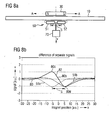
- the sensor assembly comprises a pair of axially-spaced, axially-oriented sensor devices 51 and 52.
- the sensor devices are spaced centre-to-centre by a distance S and connected subtractively (differentially) in series to SCSP circuit 70.
- Fig. 8b shows the resultant response 80.
- the zero position is where the centre of the magnet aligns with the centre of the sensor assembly 5 0, i.e. mid-way between sensors 51 and 52.
- the responses of the individual sensor devices are indicated as 51a and 51b respectively - that is with each device connected individually into circuit 70 with the same polarity.
- the curves are identical but axially offset by the spacing S.
- Each response is of the hump type.
- Curve 80 shows the combined response with the sensor devices differentially connected.
- the curve exhibits a central zero point 80b between two maxima 80c and 80d of opposite polarity between which extends a generally linear slope portion 82 which is centred on point 80b and which provides the basis of a useful linear transducer transfer function of output voltage V as a function of x-axis position or displacement.
- Fig. 9 shows the sensor assembly 50 expanded to four equally-spaced sensor devices 51-54 connected in two groups G1 (51 and 52) and G2 (53 and 54). In each group the two devices are connected additively but the two groups are connected subtractively. This results in the cancellation of a common external magnetic field component in the axial direction. Such a result can be achieved generally by having an even number of sensor devices divided into two equal groups. The groups do not have to be symmetrically arranged as in Fig. 9 for cancellation but the distribution of the groups of sensor devices will determine the overall combined response.
- the response curve pertaining to Fig. 9 is not illustrated but Figs. 10 and 11 illustrate the response curves for cases where the sensor assembly of Fig.
- Figs. 8b , 10 and 11 The following can be seen from a comparison of Figs. 8b , 10 and 11 .
- the two maxima 80c and 80d of Figs. 10 and 11 are farther spaced apart than the maxima of Fig. 8b and are significantly greater in magnitude with a corresponding enhancement of the distance range of the linear portion 82. While the maxima of Fig. 11 are b roader than those of Fig. 10 , the distance range of the linear portion is not significantly different.
- the sensitivity of the sensor assembly is also greater for Figs. 10 and 11 than for Fig. 8b , expressing sensitivity as output volts per unit distance of displacement (V/mm).
- Sensor device configurations based on Fig. 9 using equal numbers of sensor devices in each of two groups, are of e special value where cancellation of a common external axial magnetic field component is required.
- the configuration of the transducer illustrated in Fig. 12 maintains the axially-oriented magnet 30 but uses a plurality of radially-oriented sensors.
- the configuration of Fig. 12 is that of Fig. 9 but with the four sensor devices denoted 51'-54' oriented radially, that is normal to the axis of movement.
- Fig. 13 shows the basic response curve 90 for a single sensor device connected to SCSP circuit 70 where the zero on the x- axis is where the magnet aligns centrally with the single sensor device.
- response curve 90 has a zero crossing 90b at the zero position p oint bounded by two maxima 90c and 90d of opposite polarity and joined by a portion 92 of generally linear slope extending through point 90b.
- the shape of this response may be referred to as the basic linear slope - zero crossing response and the general shape is somewhat pronounced of the more useful combined response of Fig. 8b .
- Extension of this configuration to two sensor devices is illustrated in Fig. 14 which shows the individual response curves 51'a and 52'a for the two sensor devices spaced by a distance S. The interconnection of the two devices is indicated in Fig. 14a.
- the devices are additively connected (summed) to give the resultant response 90 which has a linear slope portion 92 of enhanced distance range and of enhanced sensitivity.
- radial sensor devices cannot provide cancellation of an external axially-directed magnetic field.
- Plural radial devices can be interconnected to provide cancellation of an external radially-directed magnetic field that is aligned with a common radial direction of maximum sensitivity of the devices. The interconnection of Fig. 14a does not afford such cancellation.
- Fig. 15 shows the overall response of a sensor assembly having four radially-oriented sensor devices 51'-54' connected in additive series as shown in Fig. 12 .
- the individual device responses 51'a-54'a are shown. From these responses it will be seen that the devices are spaced by a distance S along the axis. They can be regarded as being in two groups G1 and G2 to one side and the other of the zero position point. What is noticeable in Fig. 15 is the enhancement of the range of combined linear response 92 compared to Fig. 14 .
- This range of enhancement of linear response 92 is further increased in the response curve 90 of Fig. 16 pertaining to six spaced, radially-oriented sensor devices connected in additive series. The individual responses are shown as 51'a-56'a. Comparing Figs. 14 , 15 and 16 the progressive enhancement of the linear range of a usable transfer function is accompanied by a progressive reduction in the slope of the linear portion" or the "gain" associated with the transfer function.
- Two magnet configurations are possible: a) large aspect ratio; b) small aspect ratio.
- Fig. 17 shows a transducer using radial magnet 30' of large aspect ratio for cooperating with a sensor assembly 50 using four axial magnets 51-54.
- Fig. 17 is similar to Fig. 3 but the magnet 30 is oriented in a radial position. No response curve is shown for the configuration of Fig. 17 .
- the basic response of a single sensor device can be expected to be of the same general form as seen in Fig. 19 but with a much reduced linear slope portion.
- FIG. 18 Another radial magnet configuration is shown in the transducer of Fig. 18 .
- the radial magnet 30" is of small aspect ratio and the axial width of the magnet is substantially greater than the axial length of a sensor device.
- Fig. 19 shows the basic response curve 100 for the axial displacement of the magnet 31" with respect to a single one of axial sensor devices 51-54 connected into an SCSP 70).
- the response curve 1 00 s hows a linear slope portion 1 02 passing through a zero crossing 100b between two maxima 100c and 100d. It has been found that this linear slope is of very good linearity, i.e. of constant slope. Keeping in mind that magnetic field lines enter or emerge from a ferromagnetic surface perpendicularly to that surface, zero crossing point 100b is consistent with this and with the magnetic flux being concentrated in the vicinity of the corners of the magnet. The magnetic flux is in opposite directions adjacent the corners of the South surface.
- the axial distance between maxima 100c and 100d is approximately the axial width of the magnet, 20 mm in the example.
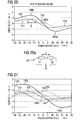
- Fig. 20 shows the response curve when the sensor assembly 50 is extended to two sensor devices 51, 52 additively connected as in Fig. 20a.
- the individual responses are indicated as 51 a, 52a.
- the devices are spaced by a distance S.
- the combined response 1 00 shows no significant range enhancement of the linear slope portion 102 over Fig. 19 though it is of higher gain (greater slope).
- all four sensor devices 51-54 of Fig. 18 are connected in additive series as shown in the figure, an appreciable enhancement of range is seen in the response of Fig. 21 ; and still further when the sensor assembly is extended to six spaced, axially-oriented sensor devices, all connected additively in series.
- the six responses 51a-56a are shown in Fig. 22 , adjacent individual responses spaced by a distance S along the axis combine to provide a linear slope portion 102 of high linearity and gain.
- the transducer configuration of Fig. 18 of a small aspect ratio radial magnet and a plurality of axially-oriented sensor devices is presently considered to be particularly advantageous, for range of linear response, especially in the six sensor device version. However, it does not provide cancellation of an external axial magnetic field.
- FIG. 23 Another configuration for a transducer is that illustrated in Fig. 23 in which a radially-oriented magnet is used in co-operation with a sensor assembly 50 of radially-oriented sensor devices.
- Fig. 23 specifically illustrates a configuration using a radial magnet 30" of small aspect ratio.
- Fig. 24 shows the basic response with one sensor device while Figs. 25-27 relate to sensor assemblies using 2, 4 and 6 sensor devices respectively.
- Fig. 24 shows the response 110 of a single sensor device 50 connected into an SCSP circuit 70. It is of a single polarity. The response is shallow having a broad maximum 110a falling gradually away toward zero with increasing distance x from the zero position. This may be categorized as a hump-type of response and can be transformed to a response having a linear slope portion with a zero crossing by including a subtractive combining of contributions from a plurality of sensor devices, either a subtractively connected pair of devices or two subtractively connected groups of devices in which the devices within a group are connected additively. This follows the teaching of the Axial Magnet -
- Fig. 25 shows the overall response 110 of two sensor devices 51'-52' spaced by a distance S and connected in subtractive series as indicated in Fig. 25a.
- the individual responses are shown as 51'a a nd 52'a and a re I ike that of Fig. 24 being of a single polarity of the hump type. These responses are transformed into a combined overall difference response 110 which exhibits a linear portion 112 passing through a zero crossing 110b between two moderate peaks 110c and 110d of opposite polarity.
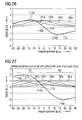
- Fig. 26 relates to the configuration shown in Fig. 23 in which the four radial sensor devices 51'-54' are connected in two groups G1 and G2 symmetrical about the zero position.
- the individual responses are indicated on Fig. 25 as 51'a-54'a.
- Devices 51' and 52' of group G1 are connected in additive series as are devices 53' and 54' of group G2. However the two groups are connected subtractively.
- the resultant overall response 110 has an enhanced portion 112 of linear slope as compared to Fig. 25 and also of greater slope - a higher gain transfer function.
- Fig. 27 takes the arrangement of Fig. 23 a step further in that each group G1 and G2 now comprises three sensor devices in a direct sequence along the axis A-A and connected additively while the groups are connected subtractively.
- the individual sensor responses are denoted 51'a-53'a for group G1 and 54'a-56'a for group G2.
- the distance range of the linear portion 112 is further enhanced as is the slope value.
- the remanence of the separator is preferably low and the magnetic field maintained at a low value commensurate with adequate measurement sensitivity. This is to avoid the creation of regions of the separator imbued with remanent or residual magnetisation.
- the sensing device(s) for example, the coils of saturating core type sensors, may be potted or encapsulated in a compound or embedded in a circuit board with an outlet plug extending therefrom.
Landscapes
- Physics & Mathematics (AREA)
- General Physics & Mathematics (AREA)
- Transmission And Conversion Of Sensor Element Output (AREA)
- Measurement Of Length, Angles, Or The Like Using Electric Or Magnetic Means (AREA)
- Measuring Fluid Pressure (AREA)
- Switches That Are Operated By Magnetic Or Electric Fields (AREA)
- Measuring Magnetic Variables (AREA)
- Inspection Of Paper Currency And Valuable Securities (AREA)
Claims (27)
- Wandler zum Erfassen einer Versetzung eines ersten Bauteils (20) entlang einer Bewegungsachse relativ zu einem zweiten Bauteil (10), umfassend:eine an dem ersten Bauteil (20) angebrachte Magnetquelle (30) zum Erzeugen eines Magnetfeldes,mehrere Magnetfeldfühler (50-53), die an dem zweiten Bauteil angebracht sind, um relativ zu dem durch die Magnetquelle (30) erzeugten Magnetfeld bewegt zu werden, wobei die mehreren Fühler (50-53) in der Richtung der Achse beabstandet sind, undeinen Schaltungsaufbau (70), mit dem die mehreren Fühler (50-53) verbunden sind, um ein Ausgabesignal zu erzeugen, das von den Eingaben der mehreren Fühler (50-53) abhängig ist, worindie Magnetquelle (30) einen Nord- und Südpol aufweist, die in der Richtung der Achse ausgerichtet sind,die mehreren Fühler (50-53) jeweils so ausgerichtet sind, dass sie auf eine axial ausgerichtete Komponente des Magnetfeldes reagieren, undworin die mehreren Fühler umfasst mindestens zwei axial beabstandete Fühler (50-53) umfassen, deren Beitrag zu dem Ausgabesignal durch Subtraktion verbunden wird,dadurch gekennzeichnet, dass zwischen der Magnetquelle (30) und der mehreren Magnetfeldfühlern (50-53) ein intervenierendes ferromagnetisches Material (10) angeordnet ist.
- Wandler nach Anspruch 1, worin die zwei Fühler (50-53) entsprechend Elemente zweier Gruppen (54a, 54b) von Fühlern (50-53) sind, wobei die Einrichtungen in der ersten Gruppe additiv miteinander verbunden sind, wobei die Einrichtungen in der zweiten Gruppe durch additiv miteinander verbunden sind und wobei die erste und zweite Gruppe von Fühlern (50-53) subtrahierend miteinander verbunden sind.
- Wandler nach Anspruch 2, worin die zwei Gruppen die gleiche Anzahl von Fühlern (50-53) beinhaltet.
- Wandler nach Anspruch 1, worin die mehreren Fühler (50-53) jeweils so ausgerichtet sind, dass sie auf die radial ausgerichtete Komponente des Magnetfeldes bezüglich der Richtung der Achse reagieren, und worin die mehreren Fühler mindestens zwei axial beabstandete Fühler (50-53) umfassen, deren Beiträge durch Addition verbunden werden.
- Wandler nach Anspruch 4, worin die mehreren Fühler mehr als zwei Fühler (50-53) umfassen, und worin die Beiträge aller Fühler (50-53) additiv verknüpft werden.
- Wandler nach Anspruch 2 oder Anspruch 5, worin die mehreren Fühler (50-53) in zwei Gruppen vorliegen, worin jede Gruppe die gleiche Anzahl an Einrichtungen beinhaltet, worin die Fühler (50-53) in jeder Gruppe direkt hintereinander in Richtung der Achse vorliegen.
- Wandler nach einem der vorstehenden Ansprüche, worin die Magnetquelle (30) einen Magnet mit relativ großem Aspektverhältnis umfasst.
- Wandler nach Anspruch 1, worin die Magnetquelle (30) einen Nord- und Südpol aufweist, die zur Achse radial ausgerichtet sind, und wobei die mehreren Fühler mindestens zwei axial beabstandete Fühler (50-53) umfassen, deren Beiträge additiv verknüpft werden.
- Wandler nach Anspruch 8, worin die mehreren Fühler mehr als zwei Fühler (50-53) umfassen und wobei die Beiträge aller Einrichtungen additiv verknüpft werden.
- Wandler nach Anspruch 8 oder 9, worin die Magnetquelle (30) ein kleines Aspektverhältnis aufweist.
- Wandler nach Anspruch 1, worin die Magnetquelle (30) einen Nord- und Südpol aufweist, die zur Achse radial ausgerichtet sind, und worin die Fühler (50-53) der mehreren Fühler jeweils so ausgerichtet sind, dass sie auf die radial ausgerichtete Komponente des Magnetfeldes reagieren, und worin die mehreren Fühler mindestens zwei axial beabstandete Fühler (50-53) umfassen, deren Beiträge subtrahierend verbunden werden.
- Wandler nach Anspruch 11, worin die zwei Fühler (50-53) jeweils Elemente von zwei Gruppen von Fühlern (50-53) sind, wobei die Einrichtungen in der ersten Gruppe additiv miteinander verbunden sind, wobei die Einrichtungen in der zweiten Gruppen additiv miteinander verbunden sind, und wobei die erste und zweite Gruppe von Fühlern (50-53) subtrahierend verbunden sind.
- Wandler nach Anspruch 9, worin die Fühler (50-53) der mehreren Fühler in zwei Gruppen vorliegen, wobei jede Gruppe die gleiche Anzahl von Einrichtungen beinhaltet, wobei die Fühler (50-53) in jeder Gruppe direkt nacheinander in der Richtung der Achse vorliegen.
- Wandler nach Anspruch 12 oder 13, worin die Magnetquelle (30) einen Magneten mit relativ kleinem Aspektverhältnis umfasst.
- Wandler nach Anspruch 1, worin die Magnetquelle (30) einen Nord- und Südpol aufweist, die in einer bestimmten Richtung zur Achse ausgerichtet sind, wobei die Fühler (50-53) der mehreren Fühler so ausgerichtet sind, dass sie auf eine Komponente des Magnetfeldes in der bestimmten Richtung reagieren, und wobei die mehreren Fühler mindestens zwei Einrichtungen umfassen, deren Beiträge substrahierend verknüpft sind.
- Wandler nach Anspruch 15, worin mehreren Fühler zwei Gruppen von Einrichtungen umfassen, wobei jede Gruppe entlang der Achse direkt anschließend eine Einrichtung umfasst, wobei die Beiträge der Einrichtungen in einer Gruppe additiv verknüpft sind und wobei die zwei Gruppen substrahierend verknüpft sind.
- Wandler nach Anspruch 15 oder 16, worin die bestimmte Richtung in der Richtung der Achse oder bezüglich der Richtung der Achse radial vorliegt.
- Wandler nach Anspruch 1, worin die Magnetquelle (30) einen Nord- und Südpol aufweist, die in eine bestimmte Richtung bezüglich der Achse ausgerichtet sind, wobei die Fühler (50-53) der mehreren Fühler jeweils so ausgerichtet sind, dass sie auf eine Komponente des Magnetfeldes normal zu der bestimmten Richtung reagieren, und wobei die mehreren Fühler mindestens zwei Einrichtungen umfassen, deren Beiträge additiv verknüpft sind.
- Wandler nach Anspruch 18, worin die mehreren Fühler mehr als zwei Fühler (50-53) umfassen, wobei die Beiträge aller additiv verknüpft sind.
- Wandler nach Anspruch 18 oder 19, worin die bestimmte Richtung in der Richtung der Achse vorliegt oder bezüglich der Richtung der Achse radial vorliegt.
- Wandler nach einem der vorstehenden Ansprüche, worin jeder Fühler (50-53) vom Kernsättigungstyp ist.
- Wandler nach Anspruch 21, worin alle Fühler (50-53) der mehreren Fühler in einer Signalaufbereitungs- und -Verarbeitungs-Schaltung in Reihe geschaltet vorliegen, die auf die Beiträge aller Einrichtungen reagiert.
- Wandler nach Anspruch 1, worin mindestens eine Magnetquelle (30) in einem ersten Bauteil (20) angeordnet ist und worin mindestens einen Magnetfeldsensor an dem zweiten Bauteil (10) angeordnet ist, um relativ zu dem durch die Quelle erzeugten Magnetfeld bewegt werden zu können, wobei der mindestens eine Magnetdetektor mit einer Schaltung verbunden ist, die ein Ausgabesignal erstellt, das eine Funktion der relativen Position der ersten und zweiten Bauteile (10) darstellt, worin eine der mindestens einen Magnetquelle (30) und der mindestens eine Magnetfeldsensor zwei Einrichtungen umfassen, die in der Richtung einer relativen Bewegung beabstandet sind, so dass das Ausgabesignal eine monotone Funktion der relativen Position der ersten und zweiten Bauteile (10) über einen Bereich einer Versetzung darstellt.
- Wandler nach Anspruch 23, worin die mindestens eine Magnetquelle (30) radial ausgerichtet vorliegt und wobei die mindestens eine Magnetfeldfühler-Einrichtung in Richtung der Versetzung ausgerichtet ist oder umgekehrt.
- Wandler nach Anspruch 23 oder 24, worin der mindestens eine Fühler mehrere Einrichtungen umfasst, die in Richtung einer relativen Versetzung beabstandet vorliegen.
- Wandler nach Anspruch 25, worin die mehreren Einrichtungen in zwei Gruppen von Einrichtungen vorliegen, in denen die Einrichtungen in den Gruppen voneinander beabstandet vorliegen, vorzugsweise in einem Abstand, der größer ist als ein Abstand der Einrichtungen innerhalb der Gruppen.
- Wandler nach einem der Ansprüche 23 bis 26, worin zwischen der mindestens einen Magnetquelle (30) und dem mindestens einen Magnetfeldsensor ferromagnetisches Material angeordnet ist, und worin und die Quelle(n) und der/die Sensor(en) in naher Nachbarschaft auf abgewandten Seiten des ferromagnetischen Materials angebracht vorliegen.
Applications Claiming Priority (5)
| Application Number | Priority Date | Filing Date | Title |
|---|---|---|---|
| GB0209240A GB0209240D0 (en) | 2002-04-23 | 2002-04-23 | Magnetic displacement sensor |
| GB0209240 | 2002-04-23 | ||
| GB0225160 | 2002-10-29 | ||
| GB0225160A GB0225160D0 (en) | 2002-10-29 | 2002-10-29 | Magnetic displacement transducer |
| PCT/EP2003/004355 WO2003091654A2 (en) | 2002-04-23 | 2003-04-23 | Magnetic displacement transducer |
Publications (2)
| Publication Number | Publication Date |
|---|---|
| EP1497620A2 EP1497620A2 (de) | 2005-01-19 |
| EP1497620B1 true EP1497620B1 (de) | 2009-03-25 |
Family
ID=29271994
Family Applications (1)
| Application Number | Title | Priority Date | Filing Date |
|---|---|---|---|
| EP03727370A Expired - Lifetime EP1497620B1 (de) | 2002-04-23 | 2003-04-23 | Magnetischer wegsensor |
Country Status (6)
| Country | Link |
|---|---|
| US (1) | US7521923B2 (de) |
| EP (1) | EP1497620B1 (de) |
| AT (1) | ATE426794T1 (de) |
| AU (1) | AU2003233072A1 (de) |
| DE (1) | DE60326830D1 (de) |
| WO (1) | WO2003091654A2 (de) |
Families Citing this family (16)
| Publication number | Priority date | Publication date | Assignee | Title |
|---|---|---|---|---|
| FR2864227B1 (fr) * | 2003-12-22 | 2006-08-25 | Sc2N Sa | Capteur magnetique de position |
| TW200537074A (en) * | 2004-01-28 | 2005-11-16 | Prakash Krishna Ratnaparkhi | A scale |
| FR2866110B1 (fr) * | 2004-02-06 | 2006-05-05 | Electricfil Automotive | Procede pour corriger un capteur de position, le decalage entre le passage d'un element magnetique et le signal logique detecte, et capteur en faisant application |
| DE102004060771B4 (de) * | 2004-12-17 | 2006-12-21 | Audi Ag | Vorrichtung zum Schalten von Übersetzungsänderungen |
| US7533607B2 (en) * | 2005-04-19 | 2009-05-19 | Pressline Services | Sidelay register for a plate cylinder of a rotary press |
| US8237443B2 (en) * | 2007-11-16 | 2012-08-07 | Baker Hughes Incorporated | Position sensor for a downhole completion device |
| FR2933202B1 (fr) * | 2008-06-27 | 2010-12-10 | Centre Nat Etd Spatiales | Dispositif et procede de mesure de champ magnetique |
| US20100301846A1 (en) * | 2009-06-01 | 2010-12-02 | Magna-Lastic Devices, Inc. | Magnetic speed sensor and method of making the same |
| US8324890B2 (en) * | 2009-09-18 | 2012-12-04 | Delphi Technologies, Inc. | Clutch position sensor for vehicle transmission |
| US9448087B2 (en) | 2011-10-10 | 2016-09-20 | Methode Electronics, Inc. | Contactless magnetic linear position sensor |
| CA2935373A1 (en) | 2013-12-30 | 2015-07-09 | Methode Electronics, Inc. | Magnetoelastic sensor |
| US10254181B2 (en) | 2014-03-26 | 2019-04-09 | Methode Electronics, Inc. | Systems and methods for reducing rotation noise in a magnetoelastic device and measuring torque, speed, and orientation |
| US11815352B2 (en) | 2015-02-17 | 2023-11-14 | Schlumberger Technology Corporation | Apparatus and method for determining borehole size with a borehole imaging tool |
| JP6682657B2 (ja) | 2016-04-29 | 2020-04-15 | ティディケイ−ミクロナス ゲー・エム・ベー・ハー | 距離測定装置 |
| US11600085B2 (en) * | 2020-07-27 | 2023-03-07 | International Business Machines Corporation | Automated training data collection for object detection |
| US20250370160A1 (en) * | 2024-06-04 | 2025-12-04 | Halliburton Energy Services, Inc. | Sensing an ac signal parameter of an electromagnetic assembly of a downhole device to estimate the status or health thereof |
Family Cites Families (21)
| Publication number | Priority date | Publication date | Assignee | Title |
|---|---|---|---|---|
| US3332009A (en) * | 1963-11-04 | 1967-07-18 | United States Steel Corp | Apparatus for detecting the relative location of a member in a selected coordinate direction |
| US4100480A (en) * | 1976-08-20 | 1978-07-11 | Dataproducts Corporation | Position and velocity sensors |
| JPH04282417A (ja) * | 1991-03-08 | 1992-10-07 | Hitachi Metals Ltd | 磁気センサ |
| JPH05175483A (ja) * | 1991-12-24 | 1993-07-13 | Asahi Chem Ind Co Ltd | 位置センサー |
| DE4341810B4 (de) | 1993-12-08 | 2004-01-29 | Festo Ag & Co | Sensoreinrichtung zur Positionserkennung eines Kolbens |
| DE4404988A1 (de) | 1994-02-17 | 1995-08-24 | Bosch Gmbh Robert | Elektrowerkzeug mit Spannvorrichtung zur Erfassung der Öffnungsweite |
| DE4430467A1 (de) | 1994-08-27 | 1995-10-19 | Danfoss As | Anordnung zum Messen der Lage eines beweglichen Gegenstands |
| US5589769A (en) * | 1994-09-30 | 1996-12-31 | Honeywell Inc. | Position detection apparatus including a circuit for receiving a plurality of output signal values and fitting the output signal values to a curve |
| US6246233B1 (en) * | 1994-12-30 | 2001-06-12 | Northstar Technologies Inc. | Magnetoresistive sensor with reduced output signal jitter and temperature compensation |
| GB9709710D0 (en) | 1997-05-13 | 1997-07-02 | Fet Electronics Ltd | Conditioner circuit for torque sensor |
| US6097183A (en) * | 1998-04-14 | 2000-08-01 | Honeywell International Inc. | Position detection apparatus with correction for non-linear sensor regions |
| US6181128B1 (en) * | 1998-09-28 | 2001-01-30 | General Motors Corporation | Magnetic beam flow sensor |
| FR2792403B1 (fr) * | 1999-04-14 | 2001-05-25 | Roulements Soc Nouvelle | Capteur de position et/ou de deplacement comportant une pluralite d'elements sensibles alignes |
| US6265867B1 (en) * | 1999-05-19 | 2001-07-24 | Arthur D. Little, Inc. | Position encoder utilizing fluxgate sensors |
| US6674280B1 (en) * | 1999-12-31 | 2004-01-06 | Honeywell International Inc. | Position detection apparatus with distributed bridge sensor |
| US6424145B1 (en) * | 2000-02-29 | 2002-07-23 | Eldec Corporation | Inductive proximity sensor for detecting ferromagnetic, non-permeable or magnet targets |
| JP2002022403A (ja) * | 2000-07-13 | 2002-01-23 | Tokyo Keiso Co Ltd | 変位検出器および変位検出方法 |
| US6489771B1 (en) * | 2000-07-20 | 2002-12-03 | Farque Claude A. | Passive external noise-canceling dynamic magnetic flux sensor for detecting the presence and direction of movement of a pig in a pipe |
| AU2002213899A1 (en) | 2000-09-12 | 2002-03-26 | Fast Technology Ag. | Magnetic torque sensor system |
| US6653830B2 (en) * | 2001-12-14 | 2003-11-25 | Wabash Technologies, Inc. | Magnetic position sensor having shaped pole pieces to provide a magnetic field having a varying magnetic flux density field strength |
| US7009386B2 (en) * | 2002-01-02 | 2006-03-07 | Stoneridge Control Devices, Inc. | Non-contact position sensor utilizing multiple sensor elements |
-
2003
- 2003-04-22 US US10/419,995 patent/US7521923B2/en not_active Expired - Lifetime
- 2003-04-23 AT AT03727370T patent/ATE426794T1/de not_active IP Right Cessation
- 2003-04-23 DE DE60326830T patent/DE60326830D1/de not_active Expired - Lifetime
- 2003-04-23 WO PCT/EP2003/004355 patent/WO2003091654A2/en not_active Ceased
- 2003-04-23 EP EP03727370A patent/EP1497620B1/de not_active Expired - Lifetime
- 2003-04-23 AU AU2003233072A patent/AU2003233072A1/en not_active Abandoned
Also Published As
| Publication number | Publication date |
|---|---|
| WO2003091654A3 (en) | 2004-04-01 |
| US7521923B2 (en) | 2009-04-21 |
| AU2003233072A1 (en) | 2003-11-10 |
| AU2003233072A8 (en) | 2003-11-10 |
| ATE426794T1 (de) | 2009-04-15 |
| WO2003091654A2 (en) | 2003-11-06 |
| DE60326830D1 (de) | 2009-05-07 |
| US20040036467A1 (en) | 2004-02-26 |
| EP1497620A2 (de) | 2005-01-19 |
Similar Documents
| Publication | Publication Date | Title |
|---|---|---|
| EP1497620B1 (de) | Magnetischer wegsensor | |
| EP3954972B1 (de) | Magnetoresistiver trägheitssensorchip | |
| US4810965A (en) | Position detecting apparatus using a magnetic sensor and a closed magnetic circuit with non-uniform magnetic flux distribution | |
| US7305882B1 (en) | Accelerometer using magnetic transducer technology | |
| US5831431A (en) | Miniaturized coil arrangement made by planar technology, for the detection of ferromagnetic materials | |
| US6670806B2 (en) | Magnetic position sensor for measuring linear displacement | |
| EP2713140A1 (de) | Magnetfeldsensorsystem mit einem Vorspannmagnet zur Erzeugung eines räumlich symmetrischen Magnetfelds auf einer von magnetoresistiven Sensorelementen definierten Ebene | |
| US20070114992A1 (en) | Closed-loop magnetic sensor system | |
| US7584672B2 (en) | Magnetostrictive torque sensor | |
| JP4621987B2 (ja) | 磁気式エンコーダ装置およびアクチュエータ | |
| EP2438391B1 (de) | Temperaturfester magnetischer linearverschiebungssensor | |
| JPH01187424A (ja) | トルクセンサ | |
| WO2011102050A1 (ja) | 磁気式位置検出装置 | |
| JP2012078232A (ja) | 電流検出装置 | |
| US5763972A (en) | Magnetic bearing with alternating actuators and sensors | |
| JP2002228733A (ja) | 磁気検出装置 | |
| JP3400641B2 (ja) | 直線変位検出装置 | |
| JP3501625B2 (ja) | 検知装置及びそれを用いたシリンダ装置 | |
| JPS6344730Y2 (de) | ||
| JP3386723B2 (ja) | 磁気検知装置 | |
| US6211669B1 (en) | Magnetic detector with improved noise resistance characteristics | |
| RU15609U1 (ru) | Датчик ускорения | |
| Bratland et al. | Linear position sensing using magnetoresistive sensors | |
| RU2084912C1 (ru) | Датчик магнитного поля | |
| JP2005221492A (ja) | 電流センサおよび電力監視システム |
Legal Events
| Date | Code | Title | Description |
|---|---|---|---|
| PUAI | Public reference made under article 153(3) epc to a published international application that has entered the european phase |
Free format text: ORIGINAL CODE: 0009012 |
|
| 17P | Request for examination filed |
Effective date: 20041014 |
|
| AK | Designated contracting states |
Kind code of ref document: A2 Designated state(s): AT BE BG CH CY CZ DE DK EE ES FI FR GB GR HU IE IT LI LU MC NL PT RO SE SI SK TR |
|
| AX | Request for extension of the european patent |
Extension state: AL LT LV MK |
|
| RAP1 | Party data changed (applicant data changed or rights of an application transferred) |
Owner name: ABAS INCORPORATED |
|
| 17Q | First examination report despatched |
Effective date: 20061212 |
|
| GRAP | Despatch of communication of intention to grant a patent |
Free format text: ORIGINAL CODE: EPIDOSNIGR1 |
|
| RIC1 | Information provided on ipc code assigned before grant |
Ipc: G01D 5/14 20060101AFI20081022BHEP |
|
| RIN1 | Information on inventor provided before grant (corrected) |
Inventor name: MAY, LUTZ, AXEL Inventor name: CUNTZE, GEORG |
|
| GRAS | Grant fee paid |
Free format text: ORIGINAL CODE: EPIDOSNIGR3 |
|
| GRAA | (expected) grant |
Free format text: ORIGINAL CODE: 0009210 |
|
| AK | Designated contracting states |
Kind code of ref document: B1 Designated state(s): AT BE BG CH CY CZ DE DK EE ES FI FR GB GR HU IE IT LI LU MC NL PT RO SE SI SK TR |
|
| REG | Reference to a national code |
Ref country code: GB Ref legal event code: FG4D |
|
| REG | Reference to a national code |
Ref country code: CH Ref legal event code: EP |
|
| REG | Reference to a national code |
Ref country code: IE Ref legal event code: FG4D |
|
| REF | Corresponds to: |
Ref document number: 60326830 Country of ref document: DE Date of ref document: 20090507 Kind code of ref document: P |
|
| PG25 | Lapsed in a contracting state [announced via postgrant information from national office to epo] |
Ref country code: FI Free format text: LAPSE BECAUSE OF FAILURE TO SUBMIT A TRANSLATION OF THE DESCRIPTION OR TO PAY THE FEE WITHIN THE PRESCRIBED TIME-LIMIT Effective date: 20090325 Ref country code: SI Free format text: LAPSE BECAUSE OF FAILURE TO SUBMIT A TRANSLATION OF THE DESCRIPTION OR TO PAY THE FEE WITHIN THE PRESCRIBED TIME-LIMIT Effective date: 20090325 |
|
| PG25 | Lapsed in a contracting state [announced via postgrant information from national office to epo] |
Ref country code: SE Free format text: LAPSE BECAUSE OF FAILURE TO SUBMIT A TRANSLATION OF THE DESCRIPTION OR TO PAY THE FEE WITHIN THE PRESCRIBED TIME-LIMIT Effective date: 20090625 Ref country code: AT Free format text: LAPSE BECAUSE OF FAILURE TO SUBMIT A TRANSLATION OF THE DESCRIPTION OR TO PAY THE FEE WITHIN THE PRESCRIBED TIME-LIMIT Effective date: 20090325 |
|
| NLV1 | Nl: lapsed or annulled due to failure to fulfill the requirements of art. 29p and 29m of the patents act | ||
| PG25 | Lapsed in a contracting state [announced via postgrant information from national office to epo] |
Ref country code: BE Free format text: LAPSE BECAUSE OF FAILURE TO SUBMIT A TRANSLATION OF THE DESCRIPTION OR TO PAY THE FEE WITHIN THE PRESCRIBED TIME-LIMIT Effective date: 20090325 |
|
| PG25 | Lapsed in a contracting state [announced via postgrant information from national office to epo] |
Ref country code: EE Free format text: LAPSE BECAUSE OF FAILURE TO SUBMIT A TRANSLATION OF THE DESCRIPTION OR TO PAY THE FEE WITHIN THE PRESCRIBED TIME-LIMIT Effective date: 20090325 Ref country code: CZ Free format text: LAPSE BECAUSE OF FAILURE TO SUBMIT A TRANSLATION OF THE DESCRIPTION OR TO PAY THE FEE WITHIN THE PRESCRIBED TIME-LIMIT Effective date: 20090325 Ref country code: ES Free format text: LAPSE BECAUSE OF FAILURE TO SUBMIT A TRANSLATION OF THE DESCRIPTION OR TO PAY THE FEE WITHIN THE PRESCRIBED TIME-LIMIT Effective date: 20090706 Ref country code: PT Free format text: LAPSE BECAUSE OF FAILURE TO SUBMIT A TRANSLATION OF THE DESCRIPTION OR TO PAY THE FEE WITHIN THE PRESCRIBED TIME-LIMIT Effective date: 20090901 |
|
| PG25 | Lapsed in a contracting state [announced via postgrant information from national office to epo] |
Ref country code: SK Free format text: LAPSE BECAUSE OF FAILURE TO SUBMIT A TRANSLATION OF THE DESCRIPTION OR TO PAY THE FEE WITHIN THE PRESCRIBED TIME-LIMIT Effective date: 20090325 Ref country code: RO Free format text: LAPSE BECAUSE OF FAILURE TO SUBMIT A TRANSLATION OF THE DESCRIPTION OR TO PAY THE FEE WITHIN THE PRESCRIBED TIME-LIMIT Effective date: 20090325 Ref country code: NL Free format text: LAPSE BECAUSE OF FAILURE TO SUBMIT A TRANSLATION OF THE DESCRIPTION OR TO PAY THE FEE WITHIN THE PRESCRIBED TIME-LIMIT Effective date: 20090325 |
|
| REG | Reference to a national code |
Ref country code: CH Ref legal event code: PL |
|
| PG25 | Lapsed in a contracting state [announced via postgrant information from national office to epo] |
Ref country code: LI Free format text: LAPSE BECAUSE OF NON-PAYMENT OF DUE FEES Effective date: 20090430 Ref country code: DK Free format text: LAPSE BECAUSE OF FAILURE TO SUBMIT A TRANSLATION OF THE DESCRIPTION OR TO PAY THE FEE WITHIN THE PRESCRIBED TIME-LIMIT Effective date: 20090325 Ref country code: BG Free format text: LAPSE BECAUSE OF FAILURE TO SUBMIT A TRANSLATION OF THE DESCRIPTION OR TO PAY THE FEE WITHIN THE PRESCRIBED TIME-LIMIT Effective date: 20090625 Ref country code: CH Free format text: LAPSE BECAUSE OF NON-PAYMENT OF DUE FEES Effective date: 20090430 |
|
| PLBE | No opposition filed within time limit |
Free format text: ORIGINAL CODE: 0009261 |
|
| STAA | Information on the status of an ep patent application or granted ep patent |
Free format text: STATUS: NO OPPOSITION FILED WITHIN TIME LIMIT |
|
| REG | Reference to a national code |
Ref country code: IE Ref legal event code: MM4A |
|
| 26N | No opposition filed |
Effective date: 20091229 |
|
| PG25 | Lapsed in a contracting state [announced via postgrant information from national office to epo] |
Ref country code: IE Free format text: LAPSE BECAUSE OF NON-PAYMENT OF DUE FEES Effective date: 20090423 Ref country code: MC Free format text: LAPSE BECAUSE OF NON-PAYMENT OF DUE FEES Effective date: 20090430 |
|
| PG25 | Lapsed in a contracting state [announced via postgrant information from national office to epo] |
Ref country code: GR Free format text: LAPSE BECAUSE OF FAILURE TO SUBMIT A TRANSLATION OF THE DESCRIPTION OR TO PAY THE FEE WITHIN THE PRESCRIBED TIME-LIMIT Effective date: 20090626 |
|
| PG25 | Lapsed in a contracting state [announced via postgrant information from national office to epo] |
Ref country code: IT Free format text: LAPSE BECAUSE OF FAILURE TO SUBMIT A TRANSLATION OF THE DESCRIPTION OR TO PAY THE FEE WITHIN THE PRESCRIBED TIME-LIMIT Effective date: 20090325 |
|
| PG25 | Lapsed in a contracting state [announced via postgrant information from national office to epo] |
Ref country code: LU Free format text: LAPSE BECAUSE OF NON-PAYMENT OF DUE FEES Effective date: 20090423 |
|
| PG25 | Lapsed in a contracting state [announced via postgrant information from national office to epo] |
Ref country code: HU Free format text: LAPSE BECAUSE OF FAILURE TO SUBMIT A TRANSLATION OF THE DESCRIPTION OR TO PAY THE FEE WITHIN THE PRESCRIBED TIME-LIMIT Effective date: 20090926 |
|
| PG25 | Lapsed in a contracting state [announced via postgrant information from national office to epo] |
Ref country code: TR Free format text: LAPSE BECAUSE OF FAILURE TO SUBMIT A TRANSLATION OF THE DESCRIPTION OR TO PAY THE FEE WITHIN THE PRESCRIBED TIME-LIMIT Effective date: 20090325 |
|
| PG25 | Lapsed in a contracting state [announced via postgrant information from national office to epo] |
Ref country code: CY Free format text: LAPSE BECAUSE OF FAILURE TO SUBMIT A TRANSLATION OF THE DESCRIPTION OR TO PAY THE FEE WITHIN THE PRESCRIBED TIME-LIMIT Effective date: 20090325 |
|
| REG | Reference to a national code |
Ref country code: FR Ref legal event code: PLFP Year of fee payment: 14 |
|
| REG | Reference to a national code |
Ref country code: FR Ref legal event code: PLFP Year of fee payment: 15 |
|
| REG | Reference to a national code |
Ref country code: FR Ref legal event code: PLFP Year of fee payment: 16 |
|
| PGFP | Annual fee paid to national office [announced via postgrant information from national office to epo] |
Ref country code: DE Payment date: 20200408 Year of fee payment: 18 |
|
| PGFP | Annual fee paid to national office [announced via postgrant information from national office to epo] |
Ref country code: GB Payment date: 20200416 Year of fee payment: 18 |
|
| PGFP | Annual fee paid to national office [announced via postgrant information from national office to epo] |
Ref country code: FR Payment date: 20210309 Year of fee payment: 19 |
|
| REG | Reference to a national code |
Ref country code: DE Ref legal event code: R119 Ref document number: 60326830 Country of ref document: DE |
|
| GBPC | Gb: european patent ceased through non-payment of renewal fee |
Effective date: 20210423 |
|
| PG25 | Lapsed in a contracting state [announced via postgrant information from national office to epo] |
Ref country code: DE Free format text: LAPSE BECAUSE OF NON-PAYMENT OF DUE FEES Effective date: 20211103 Ref country code: GB Free format text: LAPSE BECAUSE OF NON-PAYMENT OF DUE FEES Effective date: 20210423 |
|
| PG25 | Lapsed in a contracting state [announced via postgrant information from national office to epo] |
Ref country code: FR Free format text: LAPSE BECAUSE OF NON-PAYMENT OF DUE FEES Effective date: 20220430 |