EP1497735B1 - Procede et dispositif d'inspection d'une fonction de surveillance d'un systeme de bus et systeme de bus - Google Patents
Procede et dispositif d'inspection d'une fonction de surveillance d'un systeme de bus et systeme de bus Download PDFInfo
- Publication number
- EP1497735B1 EP1497735B1 EP03720277A EP03720277A EP1497735B1 EP 1497735 B1 EP1497735 B1 EP 1497735B1 EP 03720277 A EP03720277 A EP 03720277A EP 03720277 A EP03720277 A EP 03720277A EP 1497735 B1 EP1497735 B1 EP 1497735B1
- Authority
- EP
- European Patent Office
- Prior art keywords
- subscriber
- bus system
- time
- time period
- monitoring function
- Prior art date
- Legal status (The legal status is an assumption and is not a legal conclusion. Google has not performed a legal analysis and makes no representation as to the accuracy of the status listed.)
- Expired - Lifetime
Links
Images


Classifications
-
- G—PHYSICS
- G06—COMPUTING OR CALCULATING; COUNTING
- G06F—ELECTRIC DIGITAL DATA PROCESSING
- G06F13/00—Interconnection of, or transfer of information or other signals between, memories, input/output devices or central processing units
- G06F13/38—Information transfer, e.g. on bus
- G06F13/42—Bus transfer protocol, e.g. handshake; Synchronisation
-
- H—ELECTRICITY
- H04—ELECTRIC COMMUNICATION TECHNIQUE
- H04L—TRANSMISSION OF DIGITAL INFORMATION, e.g. TELEGRAPHIC COMMUNICATION
- H04L12/00—Data switching networks
- H04L12/28—Data switching networks characterised by path configuration, e.g. LAN [Local Area Networks] or WAN [Wide Area Networks]
- H04L12/44—Star or tree networks
-
- G—PHYSICS
- G06—COMPUTING OR CALCULATING; COUNTING
- G06F—ELECTRIC DIGITAL DATA PROCESSING
- G06F13/00—Interconnection of, or transfer of information or other signals between, memories, input/output devices or central processing units
- G06F13/38—Information transfer, e.g. on bus
-
- H—ELECTRICITY
- H04—ELECTRIC COMMUNICATION TECHNIQUE
- H04L—TRANSMISSION OF DIGITAL INFORMATION, e.g. TELEGRAPHIC COMMUNICATION
- H04L12/00—Data switching networks
- H04L12/28—Data switching networks characterised by path configuration, e.g. LAN [Local Area Networks] or WAN [Wide Area Networks]
- H04L12/40—Bus networks
- H04L12/407—Bus networks with decentralised control
- H04L12/413—Bus networks with decentralised control with random access, e.g. carrier-sense multiple-access with collision detection [CSMA-CD]
- H04L12/4135—Bus networks with decentralised control with random access, e.g. carrier-sense multiple-access with collision detection [CSMA-CD] using bit-wise arbitration
-
- H—ELECTRICITY
- H04—ELECTRIC COMMUNICATION TECHNIQUE
- H04L—TRANSMISSION OF DIGITAL INFORMATION, e.g. TELEGRAPHIC COMMUNICATION
- H04L43/00—Arrangements for monitoring or testing data switching networks
-
- H—ELECTRICITY
- H04—ELECTRIC COMMUNICATION TECHNIQUE
- H04L—TRANSMISSION OF DIGITAL INFORMATION, e.g. TELEGRAPHIC COMMUNICATION
- H04L43/00—Arrangements for monitoring or testing data switching networks
- H04L43/50—Testing arrangements
-
- H—ELECTRICITY
- H04—ELECTRIC COMMUNICATION TECHNIQUE
- H04L—TRANSMISSION OF DIGITAL INFORMATION, e.g. TELEGRAPHIC COMMUNICATION
- H04L12/00—Data switching networks
- H04L12/28—Data switching networks characterised by path configuration, e.g. LAN [Local Area Networks] or WAN [Wide Area Networks]
- H04L12/46—Interconnection of networks
- H04L12/4604—LAN interconnection over a backbone network, e.g. Internet, Frame Relay
- H04L12/462—LAN interconnection over a bridge based backbone
- H04L12/4625—Single bridge functionality, e.g. connection of two networks over a single bridge
-
- H—ELECTRICITY
- H04—ELECTRIC COMMUNICATION TECHNIQUE
- H04L—TRANSMISSION OF DIGITAL INFORMATION, e.g. TELEGRAPHIC COMMUNICATION
- H04L43/00—Arrangements for monitoring or testing data switching networks
- H04L43/08—Monitoring or testing based on specific metrics, e.g. QoS, energy consumption or environmental parameters
- H04L43/0805—Monitoring or testing based on specific metrics, e.g. QoS, energy consumption or environmental parameters by checking availability
- H04L43/0817—Monitoring or testing based on specific metrics, e.g. QoS, energy consumption or environmental parameters by checking availability by checking functioning
Definitions
- the invention relates to a method and a device for checking a monitoring function of a bus system and bus system according to the preamble of the independent claims.
- the clear access to the communication system or bus system is solved by a priority-based bit arithmetic.
- a prerequisite for this is that each message is assigned a unique priority.
- the CAN protocol is very flexible. Adding more nodes and messages is easily possible while there are still free priorities.
- TTCAN time-triggered controller area network
- the invention relates to a method and a device for checking a monitoring function of a bus system and corresponding bus system with at least one subscriber, wherein first time intervals are provided, in which messages are transmitted and a number of first time segments, a communication cycle is formed such that the messages be transmitted in first time intervals, wherein the number of first time periods and the respective position of a first time period for the messages of the subscriber in the communication cycle is predetermined, now advantageously a second period is provided after the communication cycle in which no messages may be transmitted, wherein the monitoring function is checked in this second period of time.
- the big advantage of the present invention is that no time has to be consumed within the communication cycle in favor of the Busguardian test, which is normally intended for sending messages.
- the proposed test time is thus within a second time period, which is not used for active communication, the so-called Network Idle Time MT.
- the monitoring function is designed such that the messages of the subscriber, which are sent outside the first time periods specified for these messages, are blocked.
- the monitoring function is checked such that the subscriber attempts to send a test message in the second period and checks whether this test message has been disabled. It is advantageous in this case that the subscriber can read back the messages sent by himself from the bus system and thus himself carries out the check as to whether the test message has been blocked or not, that is expediently a loop-back function is available.
- the test message has a signal form that is unique in the bus system in order to distinguish it from transient irradiations, for example in the context of the EMC problem (electromagnetic compatibility).
- each participant carries out the verification of the monitoring function itself, while at the same time only a single participant may perform the verification of the monitoring function.
- the subscriber is assigned a specific period of time unambiguously for checking. This may be a third time period within a second time period or a specific time period after one concrete communication cycle, so that it is clear which participant may perform a review in which period.
- each participant is assigned a separate test message, the test messages of the individual participants differing from one another.
- test message assigned to a subscriber can only be received by one, namely the subscriber to whom it is assigned.
- an at least second participant can also carry out the verification of the monitoring function of a first participant and expediently communicate a result of this verification to the first participant.
- the bus system is constructed in a star topology, wherein each participant has a connection to a coupling element of the bus star and the coupling element is designed such that a test message of a participant is not forwarded by the coupling element to other participants, so that each participant uniquely can do a self-examination.
- FIG. 1 shows a communication network or communication system or bus system 109 with a bus 100. Coupled to this bus are participants 101 and 102, each containing a coupling element, in particular a bus controller 104 and 103, respectively. Symbolically represented in the bus coupling units 103 and 104 is a processing unit 105 or 106 and an associated bus guardian or bus guardian or the corresponding function with block 107 or block 108.
- the arrangement of the processing unit, bus controller or bus interface and monitoring function is exemplary see. Likewise, the processing in the subscriber can be carried out directly as well as the monitoring function. Any assignments of processing function and monitoring function to bus controller or subscriber itself are possible. An external arrangement of said components and functions related to the subscriber is conceivable.
- FIG. 2 now shows the communication on the bus with a first communication cycle C1, a communication cycle C2 and a communication cycle C3.
- the communication cycles are divided into several time segments, represented here by way of example by the time segments or time slots S1, S2, S3 or Sn.
- Following each communication cycle C (C1, C2,...) follows the so-called Network Idle Time NIT, here NIET1 for C 1 and NIT2 for C2.
- This Network Idle Time is a period of time that can be assigned to the current communication round but in which no messages may be sent.
- important internal protocol tasks such. Example, the calculation of the clock correction values for adapting a local time of a single subscriber to the global time of the entire bus system made.
- the transmission process of the communication system as stated cyclically constructed and structured in so-called communication cycles or communication rounds. It is advantageous that every node or subscriber or bus controller has the possibility to detect when the test has a negative result, ie. H. via a loop back the actual signals left behind.
- the bus guardian blocks the transmission possibility by the bus controller BCX.
- the latter has the option of transmitting normal messages, in this case BGN1 or BGN2, to the bus in the time slots provided here, here S3 and Sn. In these time slots, the message transmission by the bus controller BCX is enabled by the bus guardian BG, as shown by BG01 and BG02.
- a Busguardian test is now not carried out in the time available for communication, but in a time in which no communication is permitted or intended on the bus, in the so-called Network Idle Time.
- a controller here BCX
- a signal in particular a test signal, shown here with TS1 or TS2
- TS1 or TS2 send, in which case it is checked whether this transmitted signal or this message is visible on the bus or Not. If the message is visible on the bus, the blocking was faulty. If, therefore, in the sections BGTS1 and BGTS2 the corresponding test signal can be detected on the bus, then the blocking by the bus guardian is not carried out and the monitoring function is faulty.
- the signals TS1 and TS2 as test signals or test messages are transmitted by the bus controller BCX, which is represented by BGT1 or BGT2.
- the bus controller BCX which is represented by BGT1 or BGT2.
- test message or the test signal is uniquely assigned a signal shape so that it can be recognized and distinguished from other signals.
- the test can then be repeated in the same way in order to distinguish a single irradiation or a one-time false signal from a systematic error.
- a test signal can be evaluated as an error indication for the node currently being tested.
- test signals assigned to each tester or node or the like Ie. the signal form of the test signal or the test message can be distinguished from subscriber to subscriber, Busguardian to Busguardian. Then it is also possible that the Busguardian monitoring is not carried out by each participant himself, but by other participants for another participant, for example, by participant 101 for participant 102. The same applies if the test has a specific time slot or time segment, as described above, so that then other nodes can judge the success of the test or can communicate a test result to the tested subscriber, for example via a suitable acknowledge in the context of the protocol mechanism or an explicit message.
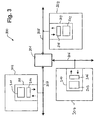
- a special embodiment represents a bus system in star topology, as in FIG. 3 is shown.
- bus subscribers 302, 303 and 304 are again shown, each containing a bus controller 305, 309 and 310, respectively.
- the same conditions and assumptions and possibilities apply as in FIG. 1 ,
- These subscribers are now each coupled to a bus 305, 306 and 307, respectively.
- the participants or the corresponding buses are connected via a coupling element 301.
- the topology of the star thus prevents overlapping of the messages or of the test procedure in the context of monitoring the Busguardian function.
Landscapes
- Engineering & Computer Science (AREA)
- Computer Networks & Wireless Communication (AREA)
- Signal Processing (AREA)
- Theoretical Computer Science (AREA)
- Physics & Mathematics (AREA)
- General Engineering & Computer Science (AREA)
- General Physics & Mathematics (AREA)
- Small-Scale Networks (AREA)
- Debugging And Monitoring (AREA)
Claims (17)
- Procédé de vérification d'une fonction de surveillance d'un système de bus qui présente au moins un participant, dans lequel
des premiers intervalles de temps dans lesquels des messages sont transmis sont prévus et un cycle de communication est formé par un certain nombre de premiers intervalles de temps de telle sorte que les messages soient transmis dans des premiers intervalles de temps,
le nombre des premiers intervalles de temps et la position de chaque premier intervalle de temps prévu pour les messages du participant étant prédéterminés dans le cycle de communication et
un deuxième intervalle de temps dans lequel la fonction de surveillance est vérifiée est prévu, caractérisé en ce que
le deuxième intervalle de temps est défini pour chaque cycle de communication et est attribué au cycle de communication,
la transmission de messages par chaque participant étant bloquée pendant le deuxième intervalle de temps. - Procédé selon la revendication 1, caractérisé en ce que des tâches internes de procès-verbal du participant au système de bus sont aussi traitées dans le deuxième intervalle de temps.
- Procédé selon la revendication 2, caractérisé en ce que comme tâche interne de procès-verbal, une valeur de correction du temps est déterminée pour adapter le temps local du participant au temps global du système de bus.
- Procédé selon les revendications 1 et 2, caractérisé en ce que la fonction de surveillance est vérifiée par le fait que le participant cherche à envoyer un message de test dans le deuxième intervalle de temps et vérifie si ce message de test a été bloqué.
- Procédé selon la revendication 4, caractérisé en ce que le participant peut relire sur le système de bus les messages qu'il a lui-même envoyés et vérifier ainsi lui-même si le message de test a été bloqué.
- Procédé selon la revendication 5, caractérisé en ce que le message de test possède dans le système de bus une forme de signal univoque qui permet de le distinguer de rayonnements transitoires.
- Procédé selon la revendication 1, caractérisé en ce que chaque participant exécute la vérification lui-même et la vérification de la fonction de surveillance ne peut être exécutée que par un seul participant à la fois.
- Procédé selon la revendication 1, caractérisé en ce qu'un troisième intervalle de temps est attribué à chaque participant et est situé à l'intérieur du deuxième intervalle de temps dans lequel seul le participant concerné peut vérifier la fonction de surveillance.
- Procédé selon la revendication 1, caractérisé en ce que chaque deuxième intervalle de temps de chaque cycle de communication est associé fixement à un participant et pendant le deuxième intervalle de temps, seul le participant concerné peut vérifier la fonction de surveillance.
- Procédé selon la revendication 8 ou 9, caractérisé en ce que chaque participant exécute lui-même la vérification.
- Procédé selon la revendication 4, caractérisé en ce que le message de test possède une forme de signal univoque et à chaque participant est associé un message de test propre, les messages de test des différents participants étant différents les uns des autres.
- Procédé selon la revendication 10, caractérisé en ce qu'un message de test associé à un participant ne peut être reçu que par ce participant.
- Procédé selon la revendication 4, caractérisé en ce qu'un message de test ou un intervalle de temps est associé de manière claire à chaque participant et au moins un deuxième participant exécute la vérification de la fonction de surveillance d'un premier participant.
- Procédé selon la revendication 13, caractérisé en ce que le ou les deuxièmes participants transmettent au premier participant le résultat de la vérification de la fonction de surveillance du premier participant.
- Dispositif de vérification d'une fonction de surveillance d'un système de bus qui présente au moins un participant, dans lequel
des premiers intervalles de temps dans lesquels des messages sont transmis sont prévus et un cycle de communication est formé par un certain nombre de premiers intervalles de temps de telle sorte que les messages soient transmis dans des premiers intervalles de temps,
le nombre des premiers intervalles de temps et la position de chaque premier intervalle de temps prévu pour les messages du participant étant prédéterminés dans le cycle de communication et
un deuxième intervalle de temps dans lequel la fonction de surveillance est vérifiée est prévu, caractérisé en ce que
le dispositif est configuré de telle sorte que le deuxième intervalle de temps est défini pour chaque cycle de communication et est attribué au cycle de communication et
en ce que la transmission de messages par chaque participant est bloquée pendant le deuxième intervalle de temps. - Système de bus doté d'un dispositif selon la revendication 15.
- Système de bus selon la revendication 16, caractérisé en ce que le système de bus présente une topologie en étoile et chaque participant possède une liaison avec un élément de couplage du système de bus dans la topologie en étoile, l'élément de couplage étant configuré de telle sorte qu'un message de test d'un participant n'est pas transmis par l'élément de couplage, chaque participant pouvant relire sur le système de bus les messages qu'il a lui-même envoyés et pouvant exécuter une auto-vérification.
Applications Claiming Priority (3)
| Application Number | Priority Date | Filing Date | Title |
|---|---|---|---|
| DE10216920A DE10216920A1 (de) | 2002-04-15 | 2002-04-15 | Verfahren und Vorrichtung zur Überprüfung einer Überwachungsfunktion eines Bussystems und Bussystem |
| DE10216920 | 2002-04-15 | ||
| PCT/DE2003/001246 WO2003088062A2 (fr) | 2002-04-15 | 2003-04-14 | Procede et dispositif d'inspection d'une fonction de surveillance d'un systeme de bus et systeme de bus |
Publications (2)
| Publication Number | Publication Date |
|---|---|
| EP1497735A2 EP1497735A2 (fr) | 2005-01-19 |
| EP1497735B1 true EP1497735B1 (fr) | 2010-06-09 |
Family
ID=28458872
Family Applications (1)
| Application Number | Title | Priority Date | Filing Date |
|---|---|---|---|
| EP03720277A Expired - Lifetime EP1497735B1 (fr) | 2002-04-15 | 2003-04-14 | Procede et dispositif d'inspection d'une fonction de surveillance d'un systeme de bus et systeme de bus |
Country Status (9)
| Country | Link |
|---|---|
| US (1) | US20050169189A1 (fr) |
| EP (1) | EP1497735B1 (fr) |
| JP (1) | JP2005522776A (fr) |
| KR (1) | KR101010483B1 (fr) |
| CN (1) | CN100367262C (fr) |
| AT (1) | ATE470906T1 (fr) |
| AU (1) | AU2003223919A1 (fr) |
| DE (2) | DE10216920A1 (fr) |
| WO (1) | WO2003088062A2 (fr) |
Families Citing this family (6)
| Publication number | Priority date | Publication date | Assignee | Title |
|---|---|---|---|---|
| EP2394394B1 (fr) | 2009-02-06 | 2016-12-07 | Broadcom Corporation | Systèmes de mesure et de diagnostic de réseau |
| CN105005254B (zh) * | 2015-07-10 | 2018-06-29 | 中国印钞造币总公司 | 一种外联设备联动检测方法及装置 |
| DE102018101103B4 (de) * | 2018-01-18 | 2026-03-12 | Volkswagen Aktiengesellschaft | Verfahren und Computerprogramme für eine Überwachungsinstanz und eine Kommunikationskomponente, Überwachungsinstanz, Kommunikationskomponente, System und Fahrzeug |
| DE102018202615A1 (de) * | 2018-02-21 | 2019-08-22 | Robert Bosch Gmbh | Teilnehmerstation für ein Bussystem und Verfahren zur Erhöhung der Datenrate eines Bussystems |
| CN113473194B (zh) * | 2020-05-09 | 2022-04-08 | 海信集团有限公司 | 一种智能设备及响应方法 |
| DE102020214945A1 (de) * | 2020-11-27 | 2022-06-02 | Robert Bosch Gesellschaft mit beschränkter Haftung | Verfahren zum Überprüfen einer Nachricht in einem Kommunikationssystem |
Family Cites Families (21)
| Publication number | Priority date | Publication date | Assignee | Title |
|---|---|---|---|---|
| US4499577A (en) * | 1982-10-18 | 1985-02-12 | At&T Bell Laboratories | Linear time division multiplexed conferencer for data transfer applications |
| EP0175095B1 (fr) * | 1984-08-23 | 1992-03-11 | Siemens Aktiengesellschaft | Procédé de transmission de données sur un bus multiprocesseur |
| JPS61154334A (ja) * | 1984-12-27 | 1986-07-14 | Fujitsu Ltd | タイムスロツト診断方式 |
| US5483518A (en) * | 1992-06-17 | 1996-01-09 | Texas Instruments Incorporated | Addressable shadow port and protocol for serial bus networks |
| DE19509558A1 (de) * | 1995-03-16 | 1996-09-19 | Abb Patent Gmbh | Verfahren zur fehlertoleranten Kommunikation unter hohen Echtzeitbedingungen |
| US5694542A (en) * | 1995-11-24 | 1997-12-02 | Fault Tolerant Systems Fts-Computertechnik Ges.M.B. | Time-triggered communication control unit and communication method |
| DE19620137C2 (de) * | 1996-05-07 | 2000-08-24 | Daimler Chrysler Ag | Protokoll für sicherheitskritische Anwendungen |
| DE19643092C2 (de) * | 1996-10-18 | 1998-07-30 | Elan Schaltelemente Gmbh | Feld-Datenbussystem |
| US6501766B1 (en) * | 1998-03-30 | 2002-12-31 | Northern Telecom Limited | Generic bus system |
| US6469997B1 (en) * | 1999-05-03 | 2002-10-22 | Motorola, Inc. | Method for transmitting collision-free messages in a digital selective call signaling protocol |
| US6931022B1 (en) * | 1999-05-28 | 2005-08-16 | Cisco Technology, Inc. | Background test system for time division multiplexing switching systems |
| US6425009B1 (en) * | 1999-06-08 | 2002-07-23 | Cisco Technology, Inc. | Monitoring redundant control buses to provide a high availability local area network for a telecommunications device |
| US6674750B1 (en) * | 1999-09-24 | 2004-01-06 | Paradyne Corporation | Apparatus and method for communicating time-division multiplexed data and packet data on a shared bus |
| DE19947657A1 (de) * | 1999-10-04 | 2001-04-12 | Bayerische Motoren Werke Ag | Betriebsverfahren für einen Datenbus für mehrere Teilnehmer mit flexiblem zeitgesteuertem Zugriff |
| DE19950433A1 (de) * | 1999-10-19 | 2001-04-26 | Philips Corp Intellectual Pty | Netzwerk mit mehreren Netzknoten zur Medienzugangsprüfung |
| DE10000303B4 (de) * | 2000-01-05 | 2011-09-29 | Robert Bosch Gmbh | Verfahren und Vorrichtung zum Austausch von Daten zwischen wenigstens zwei mit einem Bussystem verbundenen Teilnehmern |
| US6925077B1 (en) * | 2000-06-14 | 2005-08-02 | Advanced Micro Devices, Inc. | System and method for interfacing between a media access controller and a number of physical layer devices using time division multiplexing |
| US6606670B1 (en) * | 2000-08-16 | 2003-08-12 | Microchip Technology Incorporated | Circuit serial programming of default configuration |
| DE10048745C1 (de) * | 2000-09-29 | 2002-02-21 | Siemens Ag | Verfahren und Vorrichtung zur Ermittlung der Netztopologie eines Bussystems |
| DE10065113A1 (de) * | 2000-12-28 | 2002-07-04 | Bosch Gmbh Robert | Verfahren und Kommunikationssystem zum Datenaustausch zwischen Teilnehmern eines Bussystems |
| US6816736B2 (en) * | 2001-01-08 | 2004-11-09 | Lucent Technologies Inc. | Apparatus and method for use in paging mode in wireless communications systems |
-
2002
- 2002-04-15 DE DE10216920A patent/DE10216920A1/de not_active Withdrawn
-
2003
- 2003-04-14 EP EP03720277A patent/EP1497735B1/fr not_active Expired - Lifetime
- 2003-04-14 AU AU2003223919A patent/AU2003223919A1/en not_active Abandoned
- 2003-04-14 JP JP2003584930A patent/JP2005522776A/ja active Pending
- 2003-04-14 DE DE50312798T patent/DE50312798D1/de not_active Expired - Lifetime
- 2003-04-14 CN CNB038038641A patent/CN100367262C/zh not_active Expired - Fee Related
- 2003-04-14 WO PCT/DE2003/001246 patent/WO2003088062A2/fr not_active Ceased
- 2003-04-14 KR KR1020047016396A patent/KR101010483B1/ko not_active Expired - Fee Related
- 2003-04-14 US US10/510,560 patent/US20050169189A1/en not_active Abandoned
- 2003-04-14 AT AT03720277T patent/ATE470906T1/de active
Also Published As
| Publication number | Publication date |
|---|---|
| AU2003223919A1 (en) | 2003-10-27 |
| KR101010483B1 (ko) | 2011-01-21 |
| JP2005522776A (ja) | 2005-07-28 |
| CN1633646A (zh) | 2005-06-29 |
| WO2003088062A2 (fr) | 2003-10-23 |
| WO2003088062A3 (fr) | 2004-02-05 |
| DE10216920A1 (de) | 2003-10-23 |
| EP1497735A2 (fr) | 2005-01-19 |
| ATE470906T1 (de) | 2010-06-15 |
| US20050169189A1 (en) | 2005-08-04 |
| CN100367262C (zh) | 2008-02-06 |
| AU2003223919A8 (en) | 2003-10-27 |
| DE50312798D1 (de) | 2010-07-22 |
| KR20050000502A (ko) | 2005-01-05 |
Similar Documents
| Publication | Publication Date | Title |
|---|---|---|
| EP3977682B1 (fr) | Dispositif de test de détection d'erreur pour une station d'abonné d'un système de bus série et procédé de test de mécanismes de détection d'erreur lors d'une communication dans un système de bus série | |
| EP2795848B1 (fr) | Station participante à un système de bus et procédé de transmission de messages entre des stations participantes à un système de bus | |
| EP3017568A1 (fr) | Dispositif et procédé de mesure pour déterminer le temps de retard interne d'une unité d'interface de bus can | |
| EP1509005B1 (fr) | Méthode et appareil pour la transmission de données par diffusion dans un réseau bus | |
| EP3977683B1 (fr) | Dispositif pour une station d'abonné d'un système de bus série et procédé de communication dans un système de bus série | |
| EP1497735B1 (fr) | Procede et dispositif d'inspection d'une fonction de surveillance d'un systeme de bus et systeme de bus | |
| DE10360856A1 (de) | Bussystem für ein Flugzeug | |
| EP1357707B1 (fr) | Méthode pour transférer des messages via un système de bus | |
| WO2020030441A1 (fr) | Procédé de surveillance de la communication d'un système de bus d'un véhicule | |
| EP2795821B1 (fr) | Poste du réseau d'un bus système et procédé de transmission de données entre les postes du réseau d'un bus système | |
| EP1484679B1 (fr) | Méthode et système pour garantir des temps de réponses maximaux pour systèmes complexes ou distribués , sécurisés ou non | |
| DE102010063528B4 (de) | Verfahren zum Verbinden von Busleitungen zu Bussen und Vorrichtung zur Ausführung des Verfahrens | |
| DE102011005239B4 (de) | Sicherheitssystem sowie Verfahren zum Austauschen von sicherheitsgerichteten Daten in einem Sicherheitssystem | |
| EP1399818A2 (fr) | Procede et dispositif de communication dans un systeme informatique reparti tolerant aux erreurs | |
| EP1329057B1 (fr) | Procédé permettant l'access a un bus de données entre des unites electronicques en communication | |
| DE10231424B4 (de) | Vorrichtung und Verfahren zur Datenkommunikation | |
| DE102024117883A1 (de) | System zur übertragung von daten über ein, von mehreren kommunikationsteilnehmern im zeitmultiplexverfahren gemeinsam genutztes, medium | |
| WO2000018062A2 (fr) | Reseau ainsi qu'appareil de couplage pour la liaison de deux segments dans un tel reseau | |
| DE102022000991A1 (de) | Automatisierungssystem und Verfahren zum Betrieb eines Automatisierungssystem | |
| WO2000018063A2 (fr) | Reseau ainsi qu'appareil de couplage pour la liaison de deux segments dans un tel reseau | |
| DE102019125693A1 (de) | Verfahren zum Betreiben eines Kommunikationsnetzwerks, Kommunikationsnetzwerk und Teilnehmer für ein Kommunikationsnetzwerk | |
| DE10320316A1 (de) | Buswächtereinheit für einen Netzknoten | |
| WO2003081847A1 (fr) | Utilisation d'emplacements sans appartenance pour l'attribution dynamique de largeur de bande | |
| DE10115804A1 (de) | Betriebsverfahren für einen Datenbus für mehrere Teilnehmer | |
| EP3492999A1 (fr) | Procédé destiné au fonctionnement d'un système de communication, système de communication et dispositif de communication |
Legal Events
| Date | Code | Title | Description |
|---|---|---|---|
| PUAI | Public reference made under article 153(3) epc to a published international application that has entered the european phase |
Free format text: ORIGINAL CODE: 0009012 |
|
| 17P | Request for examination filed |
Effective date: 20041115 |
|
| AK | Designated contracting states |
Kind code of ref document: A2 Designated state(s): AT BE BG CH CY CZ DE DK EE ES FI FR GB GR HU IE IT LI LU MC NL PT RO SE SI SK TR |
|
| AX | Request for extension of the european patent |
Extension state: AL LT LV MK |
|
| 17Q | First examination report despatched |
Effective date: 20051102 |
|
| GRAP | Despatch of communication of intention to grant a patent |
Free format text: ORIGINAL CODE: EPIDOSNIGR1 |
|
| GRAS | Grant fee paid |
Free format text: ORIGINAL CODE: EPIDOSNIGR3 |
|
| GRAA | (expected) grant |
Free format text: ORIGINAL CODE: 0009210 |
|
| AK | Designated contracting states |
Kind code of ref document: B1 Designated state(s): AT BE BG CH CY CZ DE DK EE ES FI FR GB GR HU IE IT LI LU MC NL PT RO SE SI SK TR |
|
| REG | Reference to a national code |
Ref country code: CH Ref legal event code: EP |
|
| REG | Reference to a national code |
Ref country code: IE Ref legal event code: FG4D Free format text: LANGUAGE OF EP DOCUMENT: GERMAN |
|
| REF | Corresponds to: |
Ref document number: 50312798 Country of ref document: DE Date of ref document: 20100722 Kind code of ref document: P |
|
| REG | Reference to a national code |
Ref country code: NL Ref legal event code: VDEP Effective date: 20100609 |
|
| PG25 | Lapsed in a contracting state [announced via postgrant information from national office to epo] |
Ref country code: SE Free format text: LAPSE BECAUSE OF FAILURE TO SUBMIT A TRANSLATION OF THE DESCRIPTION OR TO PAY THE FEE WITHIN THE PRESCRIBED TIME-LIMIT Effective date: 20100609 |
|
| PG25 | Lapsed in a contracting state [announced via postgrant information from national office to epo] |
Ref country code: SI Free format text: LAPSE BECAUSE OF FAILURE TO SUBMIT A TRANSLATION OF THE DESCRIPTION OR TO PAY THE FEE WITHIN THE PRESCRIBED TIME-LIMIT Effective date: 20100609 Ref country code: FI Free format text: LAPSE BECAUSE OF FAILURE TO SUBMIT A TRANSLATION OF THE DESCRIPTION OR TO PAY THE FEE WITHIN THE PRESCRIBED TIME-LIMIT Effective date: 20100609 |
|
| PG25 | Lapsed in a contracting state [announced via postgrant information from national office to epo] |
Ref country code: CY Free format text: LAPSE BECAUSE OF FAILURE TO SUBMIT A TRANSLATION OF THE DESCRIPTION OR TO PAY THE FEE WITHIN THE PRESCRIBED TIME-LIMIT Effective date: 20100609 Ref country code: GR Free format text: LAPSE BECAUSE OF FAILURE TO SUBMIT A TRANSLATION OF THE DESCRIPTION OR TO PAY THE FEE WITHIN THE PRESCRIBED TIME-LIMIT Effective date: 20100910 |
|
| REG | Reference to a national code |
Ref country code: IE Ref legal event code: FD4D |
|
| PG25 | Lapsed in a contracting state [announced via postgrant information from national office to epo] |
Ref country code: NL Free format text: LAPSE BECAUSE OF FAILURE TO SUBMIT A TRANSLATION OF THE DESCRIPTION OR TO PAY THE FEE WITHIN THE PRESCRIBED TIME-LIMIT Effective date: 20100609 Ref country code: IE Free format text: LAPSE BECAUSE OF FAILURE TO SUBMIT A TRANSLATION OF THE DESCRIPTION OR TO PAY THE FEE WITHIN THE PRESCRIBED TIME-LIMIT Effective date: 20100609 Ref country code: EE Free format text: LAPSE BECAUSE OF FAILURE TO SUBMIT A TRANSLATION OF THE DESCRIPTION OR TO PAY THE FEE WITHIN THE PRESCRIBED TIME-LIMIT Effective date: 20100609 |
|
| PG25 | Lapsed in a contracting state [announced via postgrant information from national office to epo] |
Ref country code: CZ Free format text: LAPSE BECAUSE OF FAILURE TO SUBMIT A TRANSLATION OF THE DESCRIPTION OR TO PAY THE FEE WITHIN THE PRESCRIBED TIME-LIMIT Effective date: 20100609 Ref country code: PT Free format text: LAPSE BECAUSE OF FAILURE TO SUBMIT A TRANSLATION OF THE DESCRIPTION OR TO PAY THE FEE WITHIN THE PRESCRIBED TIME-LIMIT Effective date: 20101011 Ref country code: RO Free format text: LAPSE BECAUSE OF FAILURE TO SUBMIT A TRANSLATION OF THE DESCRIPTION OR TO PAY THE FEE WITHIN THE PRESCRIBED TIME-LIMIT Effective date: 20100609 Ref country code: SK Free format text: LAPSE BECAUSE OF FAILURE TO SUBMIT A TRANSLATION OF THE DESCRIPTION OR TO PAY THE FEE WITHIN THE PRESCRIBED TIME-LIMIT Effective date: 20100609 |
|
| PG25 | Lapsed in a contracting state [announced via postgrant information from national office to epo] |
Ref country code: IT Free format text: LAPSE BECAUSE OF FAILURE TO SUBMIT A TRANSLATION OF THE DESCRIPTION OR TO PAY THE FEE WITHIN THE PRESCRIBED TIME-LIMIT Effective date: 20100609 |
|
| PLBE | No opposition filed within time limit |
Free format text: ORIGINAL CODE: 0009261 |
|
| STAA | Information on the status of an ep patent application or granted ep patent |
Free format text: STATUS: NO OPPOSITION FILED WITHIN TIME LIMIT |
|
| PG25 | Lapsed in a contracting state [announced via postgrant information from national office to epo] |
Ref country code: DK Free format text: LAPSE BECAUSE OF FAILURE TO SUBMIT A TRANSLATION OF THE DESCRIPTION OR TO PAY THE FEE WITHIN THE PRESCRIBED TIME-LIMIT Effective date: 20100609 |
|
| 26N | No opposition filed |
Effective date: 20110310 |
|
| REG | Reference to a national code |
Ref country code: DE Ref legal event code: R097 Ref document number: 50312798 Country of ref document: DE Effective date: 20110309 |
|
| BERE | Be: lapsed |
Owner name: ROBERT BOSCH G.M.B.H. Effective date: 20110430 |
|
| PG25 | Lapsed in a contracting state [announced via postgrant information from national office to epo] |
Ref country code: MC Free format text: LAPSE BECAUSE OF NON-PAYMENT OF DUE FEES Effective date: 20110430 |
|
| REG | Reference to a national code |
Ref country code: CH Ref legal event code: PL |
|
| PG25 | Lapsed in a contracting state [announced via postgrant information from national office to epo] |
Ref country code: BE Free format text: LAPSE BECAUSE OF NON-PAYMENT OF DUE FEES Effective date: 20110430 Ref country code: LI Free format text: LAPSE BECAUSE OF NON-PAYMENT OF DUE FEES Effective date: 20110430 Ref country code: CH Free format text: LAPSE BECAUSE OF NON-PAYMENT OF DUE FEES Effective date: 20110430 |
|
| PGFP | Annual fee paid to national office [announced via postgrant information from national office to epo] |
Ref country code: GB Payment date: 20120423 Year of fee payment: 10 Ref country code: FR Payment date: 20120511 Year of fee payment: 10 |
|
| REG | Reference to a national code |
Ref country code: AT Ref legal event code: MM01 Ref document number: 470906 Country of ref document: AT Kind code of ref document: T Effective date: 20110414 |
|
| PG25 | Lapsed in a contracting state [announced via postgrant information from national office to epo] |
Ref country code: AT Free format text: LAPSE BECAUSE OF NON-PAYMENT OF DUE FEES Effective date: 20110414 |
|
| PG25 | Lapsed in a contracting state [announced via postgrant information from national office to epo] |
Ref country code: LU Free format text: LAPSE BECAUSE OF NON-PAYMENT OF DUE FEES Effective date: 20110414 |
|
| PG25 | Lapsed in a contracting state [announced via postgrant information from national office to epo] |
Ref country code: TR Free format text: LAPSE BECAUSE OF FAILURE TO SUBMIT A TRANSLATION OF THE DESCRIPTION OR TO PAY THE FEE WITHIN THE PRESCRIBED TIME-LIMIT Effective date: 20100609 Ref country code: BG Free format text: LAPSE BECAUSE OF FAILURE TO SUBMIT A TRANSLATION OF THE DESCRIPTION OR TO PAY THE FEE WITHIN THE PRESCRIBED TIME-LIMIT Effective date: 20100909 |
|
| PG25 | Lapsed in a contracting state [announced via postgrant information from national office to epo] |
Ref country code: ES Free format text: LAPSE BECAUSE OF FAILURE TO SUBMIT A TRANSLATION OF THE DESCRIPTION OR TO PAY THE FEE WITHIN THE PRESCRIBED TIME-LIMIT Effective date: 20100920 Ref country code: HU Free format text: LAPSE BECAUSE OF FAILURE TO SUBMIT A TRANSLATION OF THE DESCRIPTION OR TO PAY THE FEE WITHIN THE PRESCRIBED TIME-LIMIT Effective date: 20100609 |
|
| GBPC | Gb: european patent ceased through non-payment of renewal fee |
Effective date: 20130414 |
|
| PG25 | Lapsed in a contracting state [announced via postgrant information from national office to epo] |
Ref country code: GB Free format text: LAPSE BECAUSE OF NON-PAYMENT OF DUE FEES Effective date: 20130414 |
|
| REG | Reference to a national code |
Ref country code: FR Ref legal event code: ST Effective date: 20131231 |
|
| PG25 | Lapsed in a contracting state [announced via postgrant information from national office to epo] |
Ref country code: FR Free format text: LAPSE BECAUSE OF NON-PAYMENT OF DUE FEES Effective date: 20130430 |
|
| PGFP | Annual fee paid to national office [announced via postgrant information from national office to epo] |
Ref country code: DE Payment date: 20150624 Year of fee payment: 13 |
|
| REG | Reference to a national code |
Ref country code: DE Ref legal event code: R119 Ref document number: 50312798 Country of ref document: DE |
|
| PG25 | Lapsed in a contracting state [announced via postgrant information from national office to epo] |
Ref country code: DE Free format text: LAPSE BECAUSE OF NON-PAYMENT OF DUE FEES Effective date: 20161101 |