EP1497953B1 - Procede et systeme d'adaptation de debit de signal audio - Google Patents
Procede et systeme d'adaptation de debit de signal audio Download PDFInfo
- Publication number
- EP1497953B1 EP1497953B1 EP03723898A EP03723898A EP1497953B1 EP 1497953 B1 EP1497953 B1 EP 1497953B1 EP 03723898 A EP03723898 A EP 03723898A EP 03723898 A EP03723898 A EP 03723898A EP 1497953 B1 EP1497953 B1 EP 1497953B1
- Authority
- EP
- European Patent Office
- Prior art keywords
- variable
- storage component
- audio signal
- depth storage
- processor
- Prior art date
- Legal status (The legal status is an assumption and is not a legal conclusion. Google has not performed a legal analysis and makes no representation as to the accuracy of the status listed.)
- Expired - Lifetime
Links
Images
Classifications
-
- H—ELECTRICITY
- H04—ELECTRIC COMMUNICATION TECHNIQUE
- H04H—BROADCAST COMMUNICATION
- H04H20/00—Arrangements for broadcast or for distribution combined with broadcast
- H04H20/02—Arrangements for relaying broadcast information
- H04H20/06—Arrangements for relaying broadcast information among broadcast stations
-
- H—ELECTRICITY
- H04—ELECTRIC COMMUNICATION TECHNIQUE
- H04H—BROADCAST COMMUNICATION
- H04H60/00—Arrangements for broadcast applications with a direct linking to broadcast information or broadcast space-time; Broadcast-related systems
- H04H60/76—Arrangements characterised by transmission systems other than for broadcast, e.g. the Internet
- H04H60/78—Arrangements characterised by transmission systems other than for broadcast, e.g. the Internet characterised by source locations or destination locations
- H04H60/79—Arrangements characterised by transmission systems other than for broadcast, e.g. the Internet characterised by source locations or destination locations characterised by transmission among broadcast stations
-
- H—ELECTRICITY
- H04—ELECTRIC COMMUNICATION TECHNIQUE
- H04H—BROADCAST COMMUNICATION
- H04H60/00—Arrangements for broadcast applications with a direct linking to broadcast information or broadcast space-time; Broadcast-related systems
- H04H60/76—Arrangements characterised by transmission systems other than for broadcast, e.g. the Internet
- H04H60/81—Arrangements characterised by transmission systems other than for broadcast, e.g. the Internet characterised by the transmission system itself
-
- H—ELECTRICITY
- H04—ELECTRIC COMMUNICATION TECHNIQUE
- H04J—MULTIPLEX COMMUNICATION
- H04J3/00—Time-division multiplex systems
- H04J3/02—Details
- H04J3/06—Synchronising arrangements
- H04J3/062—Synchronisation of signals having the same nominal but fluctuating bit rates, e.g. using buffers
- H04J3/0626—Synchronisation of signals having the same nominal but fluctuating bit rates, e.g. using buffers plesiochronous multiplexing systems, e.g. plesiochronous digital hierarchy [PDH], jitter attenuators
-
- H—ELECTRICITY
- H04—ELECTRIC COMMUNICATION TECHNIQUE
- H04J—MULTIPLEX COMMUNICATION
- H04J3/00—Time-division multiplex systems
- H04J3/02—Details
- H04J3/06—Synchronising arrangements
- H04J3/062—Synchronisation of signals having the same nominal but fluctuating bit rates, e.g. using buffers
- H04J3/0632—Synchronisation of packets and cells, e.g. transmission of voice via a packet network, circuit emulation service [CES]
-
- H—ELECTRICITY
- H04—ELECTRIC COMMUNICATION TECHNIQUE
- H04L—TRANSMISSION OF DIGITAL INFORMATION, e.g. TELEGRAPHIC COMMUNICATION
- H04L47/00—Traffic control in data switching networks
- H04L47/10—Flow control; Congestion control
- H04L47/24—Traffic characterised by specific attributes, e.g. priority or QoS
-
- H—ELECTRICITY
- H04—ELECTRIC COMMUNICATION TECHNIQUE
- H04L—TRANSMISSION OF DIGITAL INFORMATION, e.g. TELEGRAPHIC COMMUNICATION
- H04L49/00—Packet switching elements
- H04L49/90—Buffering arrangements
Definitions
- the professional quality (i.e., program) audio that is produced in a studio for a commercial radio broadcast must often be relayed to a remote transmitter site for over-the-air transmission.
- One technique known in the art for relaying such program audio over significant distances is to sample the audio to produce a digital data stream, then transmit the digital data on a TDM link such as a T1 or E1 digital circuit in the Public Switched Telephone Network (PSTN), Microwave links and other media.
- PSTN Public Switched Telephone Network
- Microwave links and other media.
- the sampled data is often transmitted in a linear range, i.e., not compressed in any way.
- a common format for the digital audio data is the Audio Engineering Society / European Broadcast Union (AES/EBU) digital audio standard.
- AES/EBU is a bit-serial communications protocol for transmitting digital audio data through a single transmission line. This standard allows for two channels of audio data, up to 24 bits per sample, channel status bits for communication control and status information, and some error detection capabilities. Clocking information (i.e., sample rate), embedded in the AES/EBU bit stream, is recovered at the receiving end of the transmission path.
- the AES/EBU standard specifies the use of 32 kHz, 44.1 kHz, or 48 kHz sample rates.
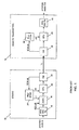
- FIG. 1 shows a prior art system for transmitting program audio in AES/EBU format from a studio site 12 to a remote transmitter site 14.
- a receive buffer 16 receives the AES/EBU data from the production source, the recovered clock and data are then provided to an asynchronous sample rate converter (ASRC) 18.
- the ASRC 18 converts the timing of the input AES/EBU data to conform to the TDM backplane clock associated with the studio multiplexor.
- the ASRC provides the data to the CPU 20 timed to the backplane clock.
- the PLL 24 derives the ASRC output clock, as well as the clock to the CPU 20, from the TDM backplane clock.
- the CPU 20 processes the AES/EBU audio data and passes this audio data to a common module (CM) 22, which implements (among other things) the T1 TDM functionality at the studio site 12.
- CM common module
- the CM 22 encapsulates the AES/EBU audio data into the T1 TDM link destined for the remote transmitter site 14.
- a second CM 26 at the remote transmitter site 14 receives the T1 data from the studio site 12, extracts the timing from the T1 signal and the AES/EBU audio data from the T1 time slots, and passes the AES/EBU data to the CPU 28.
- the PLL 32 provides a clock to the CPU 28 that is synchronized to the TDM backplane clock.
- the CPU 28 after suitable processing, provides the AES/EBU data to a transmit buffer 30, which conditions and drives the AES/EBU audio to the appropriate destination within the transmitter site 14.
- the ASRC 18 in the transmission path is synchronized to the TDM clock, so the audio data transfer from the studio site 12 to the transmitter site 14 occurs at a fairly constant rate.
- the ASRC FIR filter is a sharp-cutoff low-pass filter, which can produce "ringing" in waveforms that contain fast transitions. This can cause the peak FM deviation to be exceeded.
- the finite arithmetic representation of the samples within the FIR algorithm requires one or more requantization steps, which introduce additional noise into the system.
- the additional hardware necessary to implement the ASRC 18 adds to the overall cost of the system.
- the program audio is typically relayed to the transmitter in a linear range, i.e., without compression, to avoid similar deterioration in the audio quality. It is therefore undesirable to have the ASRC 18 in the data path.
- Document USA6092126 discloses an asynchronous sample rate tracker with rapid acquisition and good steady state performance.
- dual tracking loops are used to control reading from a FIFO sample buffer and generation of a ratio of source and local sampling rates.
- One tracking loop is used for rapid acquisition when the buffer is either empty or full with another tracking loop being used for steady-state operation.
- the steady-state tracking loop incorporates a low-pass filter to remove the effects of momentary variations in source sampling rates.
- Document USA892535 discloses a flexible and configurable system for distributing media or programming to one or more distribution networks.
- the disclosed system includes a media server, at least one server interface unit, a first communications path coupling the media server and a server interface unit, distribution network interface unit(s), and a second communications path coupling a server interface unit and the distribution network interface unit(s).
- the media server stores files of encoded (e.g., compressed) media data and files of scheduling information.
- Each of the distribution network interface unit(s) conditions received media data for transmission over the distribution network(s) which may be analog and/or digital distribution networks.
- the foregoing and other objects are achieved by the invention which in one aspect comprises a system for adapting a transmission rate of an audio signal transmitted over a time division multiplexed communications link from a source to a destination.
- the system includes a first variable-depth storage component for receiving and temporarily storing the audio signal at the source; a first processor for selectively withdrawing the audio signal from the first variable-depth storage component, for encapsulating the audio signal into packets compatible with the time division multiplexed communication link, and for transmitting the packets over the time division multiplexed communications link, wherein the amount of data in the first variable-depth storage component is dependent on the transmission rate at the source; a second processor for receiving the packets from the time division multiplexed communication link, for removing the audio signal from the encapsulating packets, and for depositing the audio signal into a second variable-depth storage component at the destination, and for adapting the transmission rate of the destination for onward transmission based on the amount of data in the second variable-depth storage component; wherein the first processor
- variable-depth storage component includes a FIFO.
- second variable-depth storage component includes a FIFO.
- the audio signal includes an AES/EBU digital audio signal.
- first processor internally implements the first variable-depth storage component
- second processor internally implements the second variable-depth storage component
- the second processor is clocked by a clocking signal derived from a signal source having a frequency that is variable according to a control signal from the second processor.
- the second processor monitors the second variable-length storage component and adjusts the control signal so as to maintain the second variable-depth storage component approximately half full.
- the signal source includes a PLL.
- Yet another embodiment further includes a signal conditioner for receiving a signal from the signal source and producing a clocking signal therefrom.
- the signal conditioner is implemented with a FPGA device.
- the first processor being clocked by a clocking signal derived from a signal source having a frequency which is variable according to a control signal derived from the time division multiplexed communications link.
- Another aspect of the invention comprises a method of adapting a transmission rate of an audio signal transmitted over a time division multiplexed communications link from a source to a destination.
- the method further includes receiving and temporarily storing the audio signal in a first variable-depth storage component at the source; selectively withdrawing the audio signal from the first variable-depth storage component as a predetermined function of an amount of data in the first variable-depth storage component, encapsulating the audio signal into packets compatible with the time division multiplexed communication link, and transmitting the packets over the time division multiplexed communications link, wherein the amount of data in the first variable-depth storage component is dependent on the transmission rate at the source; receiving the packets from the time division multiplexed communications link, removing the audio signal from the time encapsulating packets, and depositing the audio signal into a second variable depth-storage component at the destination, and selectively withdrawing the audio signal as a predetermined function of an amount of data in the second variable-depth storage component, and adapting the transmission rate based on the
- Another embodiment further includes implementing the first variable-depth storage component with a FIFO. Another embodiment further includes implementing the second variable-depth storage component with a FIFO.
- One embodiment further includes adapting the audio signal includes as an AES/EBU digital audio signal.
- Yet another embodiment further includes implementing the first variable- depth storage component and the second variable-depth storage component in code, running on one or more processors.
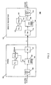
- FIG. 2 shows one embodiment of a system 100 for adapting the audio signal rate in a TDM communications system.
- the system 100 relays program audio in AES/EBU format from a studio site 102 to a remote transmitter site 104.
- the system 100 encapsulates the asynchronous AES/EBU audio data into a T1 TDM transmission without sample rate conversion, but performs any necessary rate adaptation at the studio site 102 before being transmitted and at the remote transmitter site 104, after the audio data has been extracted from the TDM transmission.
- the system 100 employs an "encapsulator” (i.e., a system or apparatus for encapsulating audio into a TDM transmission) at or near the studio site (i.e., the source), and an “extractor” (i.e., a system or apparatus for extracting the audio from a TDM transmission) at or near the remote transmitter site (i.e., the destination).
- an "encapsulator” i.e., a system or apparatus for encapsulating audio into a TDM transmission
- an “extractor” i.e., a system or apparatus for extracting the audio from a TDM transmission
- FIG. 2 shows one embodiment of the encapsulator and extractor, although other embodiment may also be used.
- a receive buffer 106 receives the AES/EBU data from the production source, conditions then provides the audio data to a CPU 108.
- the CPU 108 receives a clock from a PLL 112.
- the PLL 112 derives the clock to the CPU 108 and the PLL 112 is controlled from the internal FIFO depth in the CPU 108.
- the FIFO depth represents the amount of incoming AES/EBU data from the AES/EBU receiver 106.
- the CPU 108 uses the clock recovered from the input AES/EBU data stream to receive the AES/EBU data.
- the CPU 108 handles the AES/EBU data with a derivative of the PLL clock 112.
- the CPU 108 processes the AES/EBU audio data and passes this audio data to a common module (CM) 110, which implements (among other things) the T1 TDM functionality at the studio site 102.
- CM 110 encapsulates the AES/EBU audio data into the T1 TDM link destined for the remote transmitter site 104.
- One of the processing functions of the CPU 108 is to packetize the data into a superframe per the various transmission formats that are supported by the system 100.
- a frame packer in the CPU 108 formats the data from the audio FIFO 109 into the 8-kHz frames required by the T1/E1.
- the CPU 108 also determines how many time slots, per unit time, should be filled in the T1 TDM transmission.
- the CPU 108 therefore controls the amount of audio data and auxiliary data that is sent in the required number of timeslots used in each T1 transmission.
- a second CM 114 at the remote transmitter site 104 receives the T1 data from the studio site 102, extracts the AES/EBU audio data from the T1 time slots, and passes the AES/EBU data to the CPU 116 via the TDM bus timing.
- the CM 114 module from the T1 input extracts this TDM timing.
- a framer algorithm in the CPU 116 synchronizes itself to the superframe structure of the data packet by looking for the incrementing 4-bit pattern that exists in the first byte of each superframe to establish the frame boundaries. The frame unpacker then separates the auxillary data packets from the audio samples, and the audio samples are sent to the audio FIFO 118 in the CPU 116.
- the CPU 116 works in conjunction with a FIFO 118 to process the AES/EBU data from the CM 114.
- the AES/EBU audio data from the CM 114 is clocked into the FIFO 118 with the TDM bus clock.
- the AES/EBU data is clocked out of the CPU 1146 with the clock 124 derived by the PLL 120.
- the CPU 116 monitors the FIFO 118 and dynamically varies the control signal 122 to the PLL 120 so as to maintain the FIFO 118 at approximately half full.
- the CPU 116 detects that the FIFO 118 is greater than half full, the CPU adjusts the control signal 122 so as to increase the frequency of the first clock 124, thus increasing the rate at which the FIFO 118 is empties.
- the CPU 116 detects that the FIFO 118 is less than half full, the CPU 116 adjusts the control signal 122 so as to decrease the frequency of the first clock 124, thus decreasing the rate at which the FIFO 118 is emptied.
- the PLL 120 that produces the first clock 124 is locked to the half full flag of the FIFO 118, which is indirectly related to the original AES/EBU timing at the input of the studio 102.
- the PLL 120 is essentially locked to the original AES/EBU timing at the studio 102.
- the CPU 116 provides the AES/EBU data that has been removed from the FIFO 118 to an AES/EBU transmitter 119, which conditions and drives the AES/EBU audio to the appropriate destination within the transmitter site 104.
- U.S. Patent No. 5,818,769 entitled Dynamically Variable Digital Delay Line.
- the '769 patent describes an elastic digital delay line that implements the elasticity by varying the output rate of the delay line.
- a PLL controls the output rate of the delay line as a function of a control signal tied to the desired amount of delay, similar to the present invention that controls the output rate of the FIFO 118 as a function of the amount of data of the FIFO 118.
- Many of the same techniques taught in the 769 patent may also be used to implement various embodiments of the present invention. For example, the '769 patent teaches first adjusting the PLL according to a course resolution, and then refining the adjustment according to a fine resolution. The system 100 may also initially adjust the PLL 120 according to a coarse resolution, and then revert to a fine resolution to refine the adjustment.
- An advantage of the system 100 described herein is that at the data destination, the receiver does not need to synchronize with the media that transported the audio data.
- the receiver can therefore be designed essentially independently of the transport media, regardless of whether the media is T1/E1, optical fiber, RF, etc.
- the PLL and FIFO combination adapts to the asynchronous nature of the transported data (in this case, audio data) after the transported data is removed from the transport media.
- the inventive concepts described herein are not limited to transporting audio data, and may also be used to transport many other types of digital data known in the art.
Landscapes
- Engineering & Computer Science (AREA)
- Signal Processing (AREA)
- Computer Networks & Wireless Communication (AREA)
- Computer Hardware Design (AREA)
- Multimedia (AREA)
- Time-Division Multiplex Systems (AREA)
- Synchronisation In Digital Transmission Systems (AREA)
Abstract
Claims (17)
- Système permettant d'adapter une vitesse de transmission d'un signal audio transmis par un lien de communication multiplexé par répartition dans le temps, en provenance d'une source (102) vers une destination (104), comprenant :un premier composant de mémorisation à profondeur variable pour recevoir et mémoriser temporairement le signal audio à la source (102) ;un premier processeur (108) pour retirer de manière sélective le signal audio du premier composant de mémorisation à profondeur variable, pour encapsuler le signal audio dans des paquets compatibles avec le lien de communication multiplexé par répartition dans le temps, et pour transmettre les paquets par le lien de communication multiplexé par répartition dans le temps, dans lequel la quantité de données dans le premier composant de mémorisation à profondeur variable est dépendant de la vitesse de transmission à la source (102);un deuxième processeur (116) pour recevoir les paquets en provenance du lien de communication multiplexé par répartition dans le temps, pour enlever le signal audio des paquets d'encapsulation et pour déposer le signal audio dans un deuxième composant (118) de mémorisation à profondeur variable à la destination (104) et pour adapter la vitesse de transmission de la destination (104) pour une transmission progressive, en fonction de la quantité de données dans le deuxième composant (118) de mémorisation à profondeur variable ;dans lequel le premier processeur (108) retire de manière sélective le signal audio comme une fonction prédéterminée d'une quantité de données dans le premier composant de mémorisation à profondeur variable, et le deuxième processeur (116) retire de manière sélective le signal audio comme une fonction prédéterminée d'une quantité de données dans le deuxième composant de mémorisation à profondeur variable ;
caractérisé en ce que
le premier processeur (108) utilise une horloge variable, ladite horloge dépendant de la quantité de données dans le premier composant de mémorisation à profondeur variable, le premier processeur encapsulant le signal audio dans des paquets de taille variable, dans lequel la taille des paquets dépend de la vitesse de transmission à la source (102) ; lesdits paquets sont délivrés par le premier processeur (108) sans rééchantillonnage. - Système selon la revendication 1, dans lequel le premier composant de mémorisation à profondeur variable inclut une mémoire (109) de premier entré, premier sorti.
- Système selon la revendication 1, dans lequel le deuxième composant de mémorisation à profondeur variable inclut une mémoire (118) de premier entré, premier sorti.
- Système selon la revendication 1, dans lequel le signal audio inclut un signal audionumérique formaté à la norme de la société d'ingénierie audio et de l'union de diffusion européenne.
- Système selon la revendication 1, dans lequel le premier processeur (108) comprend en interne le premier composant de mémorisation à profondeur variable, et le deuxième processeur (116) comprend en interne le deuxième composant de mémorisation à profondeur variable.
- Système selon la revendication 1, dans lequel le deuxième processeur (118) est réglé par un signal d'horloge dérivé d'une source de signal ayant une fréquence qui est variable selon un signal de commande en provenance du deuxième processeur (118), dans lequel le deuxième processeur (118) est employé pour contrôler en continu le deuxième composant de mémorisation à profondeur variable et ajuster le signal de commande de manière à maintenir le deuxième composant de mémorisation à profondeur variable à demi plein.
- Système selon la revendication 6, dans lequel la source de signal inclut une boucle (112) de phase verrouillée.
- Système selon la revendication 6, incluant en plus un conditionneur de signal pour recevoir un signal en provenance de la source de signal et produire un signal d'horloge en provenance de cette dernière.
- Système selon la revendication 8, dans lequel le conditionneur de signal est mis en oeuvre avec un dispositif de réseau prédiffusé programmable par l'utilisateur.
- Système selon la revendication 1, le premier processeur (108) étant réglé par un signal d'horloge dérivé d'une source de signal ayant une fréquence qui est variable selon un signal de commande dérivé du lien de communication multiplexé par répartition dans le temps.
- Procédé d'adaptation d'une vitesse de transmission d'un signal audio transmis par un lien de communication multiplexé par répartition dans le temps, en provenance d'une source (102) vers une destination (104), comprenant :la réception et la mémorisation de manière temporaire du signal audio dans un premier composant de mémorisation à profondeur variable à la source (102) ;le retrait de manière sélective du signal audio du premier composant de mémorisation à profondeur variable comme une fonction prédéterminée d'une quantité de données dans le premier composant de mémorisation à profondeur variable, l'encapsulation du signal audio dans des paquets compatibles avec le lien de communication multiplexé par répartition dans le temps, et la transmission des paquets par le lien de communication multiplexé par répartition dans le temps, dans lequel la quantité de données dans le premier composant de mémorisation à profondeur variable est dépendant de la vitesse de transmission à la source (102);la réception des paquets en provenance du lien de communication multiplexé par répartition dans le temps, l'enlèvement du signal audio des paquets d'encapsulation, et le dépôt du signal audio dans un deuxième composant (118) de mémorisation à profondeur variable à la destination (104), et le retrait de manière sélective du signal audio comme une fonction prédéterminée d'une quantité de données dans le deuxième composant (118) de mémorisation à profondeur variable, et l'adaptation de la vitesse de transmission en fonction de la quantité de données dans le deuxième composant (118) de mémorisation à profondeur variable;caractérisé par les étapes consistant à
utiliser une horloge variable, ladite horloge dépendant de la quantité de données dans le premier composant de mémorisation à profondeur variable ; encapsuler le signal audio dans des paquets de taille variable, dans lequel la taille des paquets dépend de la vitesse de transmission à la source (102), transmettre lesdits paquets sans rééchantillonnage. - Procédé selon la revendication 11, incluant en outre la mise en oeuvre du premier composant de mémorisation à profondeur variable avec une mémoire (109) de premier entré, premier sorti.
- Procédé selon la revendication 11, incluant en outre la mise en oeuvre du deuxième composant de mémorisation à profondeur variable avec une mémoire (118) de premier entré, premier sorti.
- Procédé selon la revendication 11, incluant en outre l'adaptation du signal audio qui inclut un signal audionumérique formaté à la norme de la société d'ingénierie audio et de l'union de diffusion européenne.
- Procédé selon la revendication 11, incluant en outre la mise en oeuvre du premier composant de mémorisation à profondeur variable et du deuxième composant de mémorisation à profondeur variable en code, fonctionnant sur un ou plusieurs processeurs.
- Système selon la revendication 1, dans lequel les premier et deuxième composants de mémorisation à profondeur variable incluent une mémoire (109, 118) de premier entré, premier sorti et ;
le signal audio inclut un signal audio formaté à la norme de la société d'ingénierie audio et de l'union de diffusion européenne. - Procédé selon la revendication 11, incluant en outre la mise en oeuvre des premier et deuxième composants de mémorisation à profondeur variable avec une mémoire (109, 118) de premier entré, premier sorti et ;
l'adaptation du signal audio qui inclut le signal audionumérique formaté à la norme de la société d'ingénierie audio et de l'union de diffusion européenne.
Applications Claiming Priority (3)
| Application Number | Priority Date | Filing Date | Title |
|---|---|---|---|
| US37028602P | 2002-04-05 | 2002-04-05 | |
| US370286P | 2002-04-05 | ||
| PCT/US2003/010340 WO2003088535A2 (fr) | 2002-04-05 | 2003-04-04 | Procede et systeme d'adaptation de debit de signal audio |
Publications (3)
| Publication Number | Publication Date |
|---|---|
| EP1497953A2 EP1497953A2 (fr) | 2005-01-19 |
| EP1497953A4 EP1497953A4 (fr) | 2006-05-17 |
| EP1497953B1 true EP1497953B1 (fr) | 2008-07-16 |
Family
ID=29250507
Family Applications (1)
| Application Number | Title | Priority Date | Filing Date |
|---|---|---|---|
| EP03723898A Expired - Lifetime EP1497953B1 (fr) | 2002-04-05 | 2003-04-04 | Procede et systeme d'adaptation de debit de signal audio |
Country Status (7)
| Country | Link |
|---|---|
| US (1) | US7295567B2 (fr) |
| EP (1) | EP1497953B1 (fr) |
| AU (1) | AU2003230801A1 (fr) |
| DE (1) | DE60322207D1 (fr) |
| ES (1) | ES2310656T3 (fr) |
| IL (2) | IL164385A0 (fr) |
| WO (1) | WO2003088535A2 (fr) |
Families Citing this family (5)
| Publication number | Priority date | Publication date | Assignee | Title |
|---|---|---|---|---|
| US7197054B2 (en) * | 2002-06-04 | 2007-03-27 | Siemens Communications, Inc. | Methods and apparatus for conversion of one or more data streams |
| US7979561B2 (en) * | 2005-03-10 | 2011-07-12 | Qualcomm Incorporated | Method of multiplexing over an error-prone wireless broadcast channel |
| US8250394B2 (en) * | 2006-03-31 | 2012-08-21 | Stmicroelectronics International N.V. | Varying the number of generated clock signals and selecting a clock signal in response to a change in memory fill level |
| US8526458B1 (en) * | 2009-05-27 | 2013-09-03 | Lockheed Martin Corporation | Framer and deframer for self-describing superframe |
| US8737532B2 (en) | 2012-05-31 | 2014-05-27 | Silicon Laboratories Inc. | Sample rate estimator for digital radio reception systems |
Family Cites Families (9)
| Publication number | Priority date | Publication date | Assignee | Title |
|---|---|---|---|---|
| GB2267192B (en) * | 1992-05-21 | 1995-09-27 | Sony Broadcast & Communication | Sampling frequency conversion |
| AU5663296A (en) * | 1995-04-10 | 1996-10-30 | Corporate Computer Systems, Inc. | System for compression and decompression of audio signals fo r digital transmission |
| US5892535A (en) * | 1996-05-08 | 1999-04-06 | Digital Video Systems, Inc. | Flexible, configurable, hierarchical system for distributing programming |
| US6088360A (en) * | 1996-05-31 | 2000-07-11 | Broadband Networks Corporation | Dynamic rate control technique for video multiplexer |
| US6092126A (en) * | 1997-11-13 | 2000-07-18 | Creative Technology, Ltd. | Asynchronous sample rate tracker with multiple tracking modes |
| US6539011B1 (en) * | 1998-06-10 | 2003-03-25 | Merlot Communications, Inc. | Method for initializing and allocating bandwidth in a permanent virtual connection for the transmission and control of audio, video, and computer data over a single network fabric |
| US6279058B1 (en) * | 1998-07-02 | 2001-08-21 | Advanced Micro Devices, Inc. | Master isochronous clock structure having a clock controller coupling to a CPU and two data buses |
| US6252919B1 (en) * | 1998-12-17 | 2001-06-26 | Neomagic Corp. | Re-synchronization of independently-clocked audio streams by fading-in with a fractional sample over multiple periods for sample-rate conversion |
| US7035294B2 (en) * | 2001-06-04 | 2006-04-25 | Calix Networks, Inc. | Backplane bus |
-
2003
- 2003-04-04 ES ES03723898T patent/ES2310656T3/es not_active Expired - Lifetime
- 2003-04-04 WO PCT/US2003/010340 patent/WO2003088535A2/fr not_active Ceased
- 2003-04-04 IL IL16438503A patent/IL164385A0/xx unknown
- 2003-04-04 EP EP03723898A patent/EP1497953B1/fr not_active Expired - Lifetime
- 2003-04-04 AU AU2003230801A patent/AU2003230801A1/en not_active Abandoned
- 2003-04-04 DE DE60322207T patent/DE60322207D1/de not_active Expired - Lifetime
- 2003-04-04 US US10/408,060 patent/US7295567B2/en not_active Expired - Fee Related
-
2004
- 2004-10-13 IL IL164385A patent/IL164385A/en not_active IP Right Cessation
Also Published As
| Publication number | Publication date |
|---|---|
| WO2003088535A2 (fr) | 2003-10-23 |
| EP1497953A4 (fr) | 2006-05-17 |
| US7295567B2 (en) | 2007-11-13 |
| IL164385A (en) | 2010-06-16 |
| US20030219032A1 (en) | 2003-11-27 |
| EP1497953A2 (fr) | 2005-01-19 |
| IL164385A0 (en) | 2005-12-18 |
| AU2003230801A1 (en) | 2003-10-27 |
| DE60322207D1 (de) | 2008-08-28 |
| ES2310656T3 (es) | 2009-01-16 |
| AU2003230801A8 (en) | 2003-10-27 |
| WO2003088535A3 (fr) | 2004-01-22 |
Similar Documents
| Publication | Publication Date | Title |
|---|---|---|
| EP0800295B1 (fr) | Procédé et dispositif pour la transmission de paquets de données | |
| US5790538A (en) | System and method for voice Playout in an asynchronous packet network | |
| FI115354B (fi) | Kellotaajuuksien sovittaminen riippumattomissa verkoissa | |
| US6819682B1 (en) | System and method for the synchronization and distribution of telephony timing information in a cable modem network | |
| KR100923693B1 (ko) | 클록 기반 타임 슬라이싱 | |
| RU2211548C2 (ru) | Схемная эмуляция коротких пакетов | |
| US5898744A (en) | Apparatus and method for clock recovery in a communication system | |
| US9813229B2 (en) | Communication system using low bandwidth wires | |
| US6721957B1 (en) | System and method for maximizing bandwidth efficiency in a digital video program stream | |
| US6754295B1 (en) | Method and apparatus for synchronizing data transmission and reception over a network | |
| US7042908B1 (en) | Method and apparatus for transmitting arbitrary electrical signals over a data network | |
| CA2184517A1 (fr) | Recuperation du signal d'horloge pour les transmissions video dans les reseaux mta | |
| JP3045715B2 (ja) | 伝送システム、送信装置、記録再生装置、および記録装置 | |
| EP1497953B1 (fr) | Procede et systeme d'adaptation de debit de signal audio | |
| JP6097450B2 (ja) | 可変レート光トランスポンダにおけるヒットレスサービス | |
| US6658073B1 (en) | Method and system for reducing jitter on constant rate data transfer between asynchronous systems | |
| JP2003115807A (ja) | 地上デジタル放送用多重フレームtsの伝送方法及び伝送システム | |
| US5825778A (en) | VSB modulator input interfrace using simple standard | |
| CN106603216B (zh) | 一种无线微波通信系统的e1定时恢复装置及其应用 | |
| EP1178636B1 (fr) | Méthode pour la transmission synchrone de données | |
| CN100539688C (zh) | 将第一种数据流转换为第二种数据流的方法和装置 | |
| US8436938B1 (en) | Device and method for receiving data transmitted by means of an asynchronous data transmission technique | |
| CN117834597A (zh) | 一种基于arm的低延迟网络音频传输系统和方法 | |
| JP2007189584A (ja) | デジタル無線伝送システム | |
| WO2001078297A2 (fr) | Procede et appareil de synchronisation entre donnees emises et reçues sur un reseau |
Legal Events
| Date | Code | Title | Description |
|---|---|---|---|
| PUAI | Public reference made under article 153(3) epc to a published international application that has entered the european phase |
Free format text: ORIGINAL CODE: 0009012 |
|
| 17P | Request for examination filed |
Effective date: 20041104 |
|
| AK | Designated contracting states |
Kind code of ref document: A2 Designated state(s): AT BE BG CH CY CZ DE DK EE ES FI FR GB GR HU IE IT LI LU MC NL PT RO SE SI SK TR |
|
| AX | Request for extension of the european patent |
Extension state: AL LT LV MK |
|
| RIN1 | Information on inventor provided before grant (corrected) |
Inventor name: TWEED, DAVID, B. Inventor name: KANE, ALAN, P. |
|
| A4 | Supplementary search report drawn up and despatched |
Effective date: 20060403 |
|
| 17Q | First examination report despatched |
Effective date: 20060622 |
|
| 17Q | First examination report despatched |
Effective date: 20060622 |
|
| 17Q | First examination report despatched |
Effective date: 20060622 |
|
| 17Q | First examination report despatched |
Effective date: 20060622 |
|
| GRAP | Despatch of communication of intention to grant a patent |
Free format text: ORIGINAL CODE: EPIDOSNIGR1 |
|
| GRAS | Grant fee paid |
Free format text: ORIGINAL CODE: EPIDOSNIGR3 |
|
| GRAA | (expected) grant |
Free format text: ORIGINAL CODE: 0009210 |
|
| AK | Designated contracting states |
Kind code of ref document: B1 Designated state(s): DE ES FR GB |
|
| REG | Reference to a national code |
Ref country code: GB Ref legal event code: FG4D |
|
| RIN1 | Information on inventor provided before grant (corrected) |
Inventor name: TWEED, DAVID, B. Inventor name: KEANE, ALAN, P. |
|
| REF | Corresponds to: |
Ref document number: 60322207 Country of ref document: DE Date of ref document: 20080828 Kind code of ref document: P |
|
| REG | Reference to a national code |
Ref country code: ES Ref legal event code: FG2A Ref document number: 2310656 Country of ref document: ES Kind code of ref document: T3 |
|
| PLBE | No opposition filed within time limit |
Free format text: ORIGINAL CODE: 0009261 |
|
| STAA | Information on the status of an ep patent application or granted ep patent |
Free format text: STATUS: NO OPPOSITION FILED WITHIN TIME LIMIT |
|
| 26N | No opposition filed |
Effective date: 20090417 |
|
| PGFP | Annual fee paid to national office [announced via postgrant information from national office to epo] |
Ref country code: DE Payment date: 20120427 Year of fee payment: 10 |
|
| PGFP | Annual fee paid to national office [announced via postgrant information from national office to epo] |
Ref country code: GB Payment date: 20120425 Year of fee payment: 10 Ref country code: FR Payment date: 20120503 Year of fee payment: 10 |
|
| PGFP | Annual fee paid to national office [announced via postgrant information from national office to epo] |
Ref country code: ES Payment date: 20120426 Year of fee payment: 10 |
|
| REG | Reference to a national code |
Ref country code: DE Ref legal event code: R082 Ref document number: 60322207 Country of ref document: DE Representative=s name: WUESTHOFF & WUESTHOFF PATENT- UND RECHTSANWAEL, DE |
|
| REG | Reference to a national code |
Ref country code: DE Ref legal event code: R081 Ref document number: 60322207 Country of ref document: DE Owner name: HBC SOLUTIONS, INC.(NACH DEN GES. DES STAATES , US Free format text: FORMER OWNER: HARRIS CORP., MELBOURNE, US Effective date: 20130508 Ref country code: DE Ref legal event code: R082 Ref document number: 60322207 Country of ref document: DE Representative=s name: WUESTHOFF & WUESTHOFF PATENT- UND RECHTSANWAEL, DE Effective date: 20130508 |
|
| REG | Reference to a national code |
Ref country code: FR Ref legal event code: TP Owner name: HBC SOLUTIONS, INC., US Effective date: 20130807 |
|
| REG | Reference to a national code |
Ref country code: GB Ref legal event code: 732E Free format text: REGISTERED BETWEEN 20130815 AND 20130821 |
|
| GBPC | Gb: european patent ceased through non-payment of renewal fee |
Effective date: 20130404 |
|
| PG25 | Lapsed in a contracting state [announced via postgrant information from national office to epo] |
Ref country code: DE Free format text: LAPSE BECAUSE OF NON-PAYMENT OF DUE FEES Effective date: 20131101 Ref country code: GB Free format text: LAPSE BECAUSE OF NON-PAYMENT OF DUE FEES Effective date: 20130404 |
|
| REG | Reference to a national code |
Ref country code: FR Ref legal event code: ST Effective date: 20131231 |
|
| REG | Reference to a national code |
Ref country code: DE Ref legal event code: R119 Ref document number: 60322207 Country of ref document: DE Effective date: 20131101 |
|
| PG25 | Lapsed in a contracting state [announced via postgrant information from national office to epo] |
Ref country code: FR Free format text: LAPSE BECAUSE OF NON-PAYMENT OF DUE FEES Effective date: 20130430 |
|
| REG | Reference to a national code |
Ref country code: FR Ref legal event code: CA Effective date: 20140514 |
|
| REG | Reference to a national code |
Ref country code: ES Ref legal event code: FD2A Effective date: 20140714 |
|
| PG25 | Lapsed in a contracting state [announced via postgrant information from national office to epo] |
Ref country code: ES Free format text: LAPSE BECAUSE OF NON-PAYMENT OF DUE FEES Effective date: 20130405 |