EP1498042B1 - Maschine zur Herstellung von Schuhwerken - Google Patents
Maschine zur Herstellung von Schuhwerken Download PDFInfo
- Publication number
- EP1498042B1 EP1498042B1 EP20030425467 EP03425467A EP1498042B1 EP 1498042 B1 EP1498042 B1 EP 1498042B1 EP 20030425467 EP20030425467 EP 20030425467 EP 03425467 A EP03425467 A EP 03425467A EP 1498042 B1 EP1498042 B1 EP 1498042B1
- Authority
- EP
- European Patent Office
- Prior art keywords
- insole
- glue
- plate
- footwear
- machine
- Prior art date
- Legal status (The legal status is an assumption and is not a legal conclusion. Google has not performed a legal analysis and makes no representation as to the accuracy of the status listed.)
- Expired - Lifetime
Links
- 238000004519 manufacturing process Methods 0.000 title claims description 21
- 239000003292 glue Substances 0.000 claims description 67
- 238000000034 method Methods 0.000 claims description 3
- 238000006073 displacement reaction Methods 0.000 claims description 2
- 238000003825 pressing Methods 0.000 claims description 2
- 230000002452 interceptive effect Effects 0.000 claims 1
- 230000004913 activation Effects 0.000 description 11
- 229920001169 thermoplastic Polymers 0.000 description 6
- 239000004416 thermosoftening plastic Substances 0.000 description 6
- 238000004026 adhesive bonding Methods 0.000 description 5
- 239000012530 fluid Substances 0.000 description 3
- 239000000853 adhesive Substances 0.000 description 1
- 230000001070 adhesive effect Effects 0.000 description 1
- 230000002123 temporal effect Effects 0.000 description 1
- 239000012815 thermoplastic material Substances 0.000 description 1
Images


Classifications
-
- A—HUMAN NECESSITIES
- A43—FOOTWEAR
- A43D—MACHINES, TOOLS, EQUIPMENT OR METHODS FOR MANUFACTURING OR REPAIRING FOOTWEAR
- A43D119/00—Driving or controlling mechanisms of shoe machines; Frames for shoe machines
-
- A—HUMAN NECESSITIES
- A43—FOOTWEAR
- A43D—MACHINES, TOOLS, EQUIPMENT OR METHODS FOR MANUFACTURING OR REPAIRING FOOTWEAR
- A43D25/00—Devices for gluing shoe parts
- A43D25/047—Devices for lasting with adhesives or for gluing together insoles and uppers
-
- A—HUMAN NECESSITIES
- A43—FOOTWEAR
- A43D—MACHINES, TOOLS, EQUIPMENT OR METHODS FOR MANUFACTURING OR REPAIRING FOOTWEAR
- A43D25/00—Devices for gluing shoe parts
- A43D25/18—Devices for applying adhesives to shoe parts
- A43D25/183—Devices for applying adhesives to shoe parts by nozzles
-
- A—HUMAN NECESSITIES
- A43—FOOTWEAR
- A43D—MACHINES, TOOLS, EQUIPMENT OR METHODS FOR MANUFACTURING OR REPAIRING FOOTWEAR
- A43D25/00—Devices for gluing shoe parts
- A43D25/18—Devices for applying adhesives to shoe parts
- A43D25/185—Devices for applying adhesives to shoe parts by imprinter plates
Definitions
- the present invention relates to a machine for production of footwear in accordance with the preamble of claim 1.
- the upper is glued onto the insole.
- the upper is applied and stretched on a footwear last, with the base of which an insole has previously been associated. Subsequently, after having spread glue on the contour of the insole, the edges of the upper are folded and pressed onto the insole, such as to obtain the required gluing.
- the glue In order to obtain satisfactory gluing of the upper to the insole, the glue must be well supplied at the contour of the insole. Thus, it is apparent that as the shape of the insole varies, the means provided for supplying the glue must be able to supply the glue at the points required, independently of the shape of the insole.
- a machine which can carry out the above-described operation is known, for example, from patent application EP-A-1036516.
- the glue is added in the front part of the insole by means of a supplier plate which is provided with a plurality of suppliers at the rear part of the insole, by means of two movable suppliers, in order to follow the contour of the remaining part of the insole.
- the patent also specifies that when the shape and dimension of the insoles varies, the plate can adapt to the profile of the front part of the insole, whereas the two suppliers follow the contour of the insole starting from the plate.
- the problem on which the present invention is based consists of devising a machine for production of footwear, which has characteristics such as to fulfil the above-described requirements and simultaneously to eliminate the disadvantages described with reference to the known art.
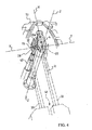
- 1 indicates as a whole a machine for pre-assembly and assembly of an upper 21 on a footwear last 2.
- a footwear insole 23 which extends between a rear end 32 and a front end 31.
- the machine 1 comprises a support frame 3, to which there are secured positioning means 5 which are designed to support the last 2 at its tip 6.
- the positioning means 5 take the form of a support element 4 which has a flat triangular surface with a limited size, on which the last 2 is designed to be positioned in a supported manner.
- the support element 4 is inclined such that the line Z-Z perpendicular to its flat triangular surface coincides substantially with the line of view of an operator who is observing the surface itself, and is standing in front of the machine 1 (at the point indicated by 0 in figure 1) .
- the machine 1 comprises an upper thruster 7, two lateral thrusters, both of which are indicated by 8, and a rear thruster 9. These thrusters are designed to engage respectively with the back 10, with the sides 11 and with the heel 12 of the last 2, in order to maintain the last itself in pressure contact against the triangular surface of the support element 4, in an operative working position ( Figures 3-5).
- a plurality of grippers are disposed around the support element 4, such as to face the contour of the tip 6 of the footwear last 2.
- the opening and closure of the grippers 13 is controlled, and they are displaced individually as required in order to obtain the desired tensioning of the upper 21 on the footwear last 2, before the gluing is carried out.
- the machine 1 also comprises means which are indicated as 14 as a whole, in order to fold the edges of the upper 21 towards the sole 15 of the footwear last 2, after opening of the grippers 13, as well as means, not shown in the_figures, to press the folded edges of the upper 21 from beneath, against the insole 23, along its contour which is provided with glue 24.
- the means 14 for folding the edges of the upper 21 comprise two arched plates 17, which reproduce the profile of the contour of the tip 6 of the footwear last 2 and are movable towards the last itself.
- the machine 1 comprises means for supplying the glue 24 onto the insole 23.
- These means comprise a glue supplier plate 19 which has a plurality of nozzles 20 and one or more glue suppliers 22, of which there are two in the example.
- the supplier plate 19 is positioned in the vicinity of the support element 4, and is shaped specifically such as to follow the profile of the front portion of a footwear last. According to a preferred embodiment, the supplier plate 19 is associated with an underlying support plate 28, by means of securing elements which are not shown in the figures.
- the supplier plate 19 can comprise a plurality of pieces which are connected to one another such as to be articulated as described, for example, in European patent application EP-1036516.
- the supplier plate 19 is movable between a rest position which is spaced from the last 2, and an operative position in which the plate 19 is in contact with the footwear last 2, and specifically with the insole 23 applied to the sole 15, in order to supply the glue along the contour 27 of the front portion of the insole 23.
- the supplier plate 19 makes it possible to supply the glue at the tip 6 of the footwear last 2.
- the plate 19 has a surface portion 19a which can be associated with the insole 23 during the glue supplying.
- the said activation means 40 do not act directly on the supplier plate 19, but on the support plate 28.
- the suppliers 22 are movable between a rest position and an operative position in which they engage from beneath with the footwear last 2, and in particular with the insole 23 applied to the sole 15, in order to supply the glue 24 along the contour 27 of the insole 23.
- the suppliers 22 are movable, i.e. they are supported by the frame 3 of the machine 1 such as to be able to move along the contour 27 of the insole 23.
- the suppliers 22 make it possible to follow the sides of the insole 23 in order to supply the glue 24 along the latter.
- the suppliers 22 are associated with a support element 33, on which there act the activation means 41 which move the suppliers 22 such that the latter move along the contour 27 of the insole 23, starting from the rear part of the insole 23.
- the suppliers 22 are supplied with a thermoplastic thread of glue (not represented in the figures), and end in a roller which makes it possible to spread the glue 24 supplied along the contour 27 of the front portion of the insole 23.
- the activation means 40, 41 can comprise for example hydraulic actuators, step-by-step electric motors or other conventional means which are normally used to automate the movement of two or more parts.
- the machine 1 can be provided with command and control means in order to control the operation of the said activation means 40, 41, i.e. in order to control the movement respectively of the plate 19 and the suppliers 22 from the rest position to the operative position.
- the rest position of the supplier plate 19 is such as to permit advance of the suppliers 22 as far as the front end 31 of the insole 23, without giving rise to interference between the supplier plate 19 and the suppliers 22 themselves.
- the rest position of the supplier plate 19 permits advance of the suppliers 22 as far as the front end 31 of the insole 23, such that the suppliers 22 are above the supplier plate 19.
- the plate 19 is displaced from the operative position to the rest position spaced from the footwear last 2, by means of translation movement parallel to the said direction Z-Z (figure 1).
- the support plate 28 is associated with a telescopic guide 42 which is movable in order to obtain displacement of the plate 19 between the rest position and the operative position and vice versa.
- the guide 42 is extended according to a straight axis parallel to the said direction Z-Z (figure 1), and is movable in this direction.
- Activation means are associated with the telescopic guide 42.
- the support plate 28 can be supported by a sliding runner on a guide which extends in the direction Z-Z.
- the slide is then activated by drive means in order to control the movement of the slide along the guide.
- the distance between the upper surface 19a of the plate 19 and the insole 23, measured along the axis Z-Z, is 10 cm or more, preferably between 10 cm and 13 cm, for example 11,5 cm.
- the plate 19 can stop in an intermediate position (I) between the rest position (R) and the operative position (O). At each actuation cycle of the machine, when use of the supplier plate 19 is required, this makes it possible to prevent long pause times which are necessary in order to displace the plate 19 from the rest position spaced from the last 2, to the operative position for supplying the glue, onto the insole 23.
- the distance between the portion of surface 19a of the plate 19 and the insole 23, measured along the axis Z-Z, is short (in the example concerned it is between 2 cm and 3 cm, preferably 2,5 cm), and is substantially shorter than the distance between the spaced rest position and the operative position for supplying, the time taken by the supplier-plate 19 to go into the operative position for supplying (figure 11) is very short.
- the supplier plate 19 is supplied with a thermoplastic thread of glue (shown in a broken line in the figures).
- a thermoplastic thread of glue shown in a broken line in the figures.
- electrical resistors which make it possible to heat the thermoplastic thread of glue such as to transform it into a fluid which can be supplied by means of the nozzles 20.
- the thread of thermoplastic material can be of the same type as that used for the suppliers 22.
- the electrical resistors of the plate 19 are supplied by a supply cable which extends inside the telescopic guide 42.
- the supplier plate 19 comprises a temperature sensor which is connected by means of an electric wire to a control unit.
- the supply cable and the electric wire of the sensor are slack, i.e. slightly longer than necessary, in order to be able to follow the plate 19 in its movement between the rest position and the operative position.
- slack i.e. slightly longer than necessary
- the telescopic guide 42 consists of tubular elements inside which there pass the supply cable for the resistors of the plate 19, the electric wire of the temperature sensor, and the thread of thermoplastic glue.
- the footwear last 2 When the machine 1 is operating, the footwear last 2 is supported in the support element 4. Subsequently, the thrusters 7, 8 and 9 fix the last 2 in its work position. By means of the grippers 13, tensioning of the upper 21 is pulled on the footwear last 2.
- the operation of the supplying means is described starting with an initial situation in which the supplier plate 19 and the suppliers 22 are in the rest position and are ready to receive the commands from the command and control means.
- the following description relates to operation of the machine 1 for gluing the upper to insoles which have medium to high rigidity and/or a tapered tip.
- the glue can advantageously be supplied solely by using the suppliers 22.
- Figures 2 and 6 show the plate 19 and the suppliers 22 in a rest position (R).
- the supplier plate 19 is in the intermediate position (I) between the rest position and the operative position (O) (fig. , the supplier plate 19 must be moved downwards, taking it from the intermediate position (I) to the rest position (O), such as to permit advance of the suppliers 22.
- the suppliers 22 are advanced from the rest position to the operative position, such as to carry out glue supplying along respective portions of the contour of the insole 23 (figures 14-18).
- Figure 3 and figures 7 to 9 show the movement of the suppliers 22 in the operative position and the plate 19 in the rest position (R).
- the suppliers 22 are able to move along the said portions of the contour of the insole 23 such as to follow a path previously stored, and to remain constantly pressed against the insole 23. By this means, the suppliers 22 keep the insole 23 pressed against the sole 15 of the last 2.
- the rest position assumed by the plate 19 allows the suppliers 22 to advance towards the front end 31 of the insole 23, without interference occurring between the supplier plate 19 and the suppliers 22. If this were not the case, i.e. if the plate 19 were in the intermediate position or in the operative position, the suppliers 22 could supply the glue along the contour 27 of the insole 23 only as far as in the vicinity of the plate 19, the presence of which would prevent further advance of the suppliers 22 towards the front end 31 of the insole 23.
- a supplier 22 is released from the insole 23 at a detachment point 29 which is positioned in the vicinity of the front end 31 of the insole 23, thus allowing only the remaining supplier 22 to continue as far as the front end of the tip of the insole (figures 14-18). Once the remaining supplier 22 also reaches the front end of the tip of the insole, the latter is released from the insole 23, and both the suppliers 22 return to the rest position.
- each supplier can supply the glue 24 along a respective and distinct portion 26 of the insole 23.
- the portions 26 determine the contour 27 of the insole 23 along which the glue 24 is applied.
- the suppliers 22 are thus movable along respective portions 26 of the contour 27 of the insole 23 which determine the said predetermined path.
- the path which is variable according to the shape of the insole 23, is stored in order to control automatically the movement of the suppliers themselves.
- Supplying the glue 24 onto the insole 23 is advantageously carried out starting from the rear part of the insole 23 towards the front end 31 of the insole 23, as shown in figure 3.
- the two suppliers 22 are both released from the insole 23 at a detachment point 29 which is located in the vicinity of the front end 31 of the insole 23.
- each supplier will pass via this point 29 at successive temporal moments, such as to prevent interference with the other supplier.
- a first supplier is released from the insole 23 at a first point 29 which is located in the vicinity of the front end 31, whereas the other supplier is released at a second point 30 which is located at a predetermined distance from the first point 32, so as not to interfere with the first supplier.
- the points 29 and 30 are indicated in the figures by way of non-limiting example, thus allowing for the possibility of modifying the position of release of the suppliers 22 according to the different design requirements and the different shapes of the insole 23.
- the glue must be applied onto a footwear last which has an extremely pointed front profile and/or the insole is not very rigid, it is necessary to intervene with an appropriately-shaped supplier plate 19.
- the use of the suppliers 22 alone is not satisfactory in terms of uniformity of glue supplying at the edges of the front end 31 of the insole 23.
- the pressure exerted by the suppliers 22 alone is not sufficient to keep the insole 23 firmly pressed against the sole 15 of the footwear last 2 in the interval of time which elapses between release of the suppliers 22 from the insole 23 and the intervention of the means for folding of the upper 21.
- the suppliers 22 are positioned in the vicinity of the supplier plate 19 (figure 10) and supply the glue 24 onto the insole 23 by moving from the plate 19 towards the rear end 32 of the insole 23 (figures 11 and 12).
- Figure 4 and figure 11 show the suppliers 22 in the operative position in the vicinity of the plate 19 and the plate in the intermediate position.
- the supplier plate 19 is moved from - the rest position (R), or, more advantageously, from the intermediate position (I), to the operative position (O), where glue is supplied onto the insole 23 via the nozzles 20.
- the glue is applied along the contour 27 of the front portion of the insole 23, in particular at the front end 31 of the insole 23.
- the activation means 40 are controlled in order to return the plate 19 to the rest position.
- the means 14 for folding the edges of the upper 21 towards the insole 23 are activated, and then the means for pressing the edges themselves against the insole 23 are activated, such as to assure correct gluing of the upper 21 to the insole 23.
- the command and control means make it possible to command and control the means for activation 40 and 41 according to the type of insole 23 onto which the upper is to be glued.
- the operator may decide to use only the suppliers 22, and not to use the supplier plate 19, or to use the said means for supplying the glue 19, 22 in succession, as described in the example previously given.
- the machine for production of footwear according to the present invention has structural and functional characteristics which can meet the above-described requirements, at the same time eliminating the disadvantages presented and described with reference to the machines according to the known art for production of footwear.
- the machine can be used in two different operative modes.
- a first operative mode only movable suppliers are used, in particular for footwear lasts which have a tapered profile and for insoles which have medium to high rigidity.
- the supplier plate is also used, in particular for footwear lasts which have a profile with an extremely pointed tip, and for insoles with low rigidity.
Landscapes
- Footwear And Its Accessory, Manufacturing Method And Apparatuses (AREA)
Claims (10)
- Maschine (1) zur Herstellung von Schuhwerk, umfassend:- Positioniermittel (5) für einen Schuhleisten (2), über den ein Obermaterial (21) gespannt wird und dem eine Schuhinnensohle (23) zugeordnet ist, die sich zwischen einem hinteren Ende (32) und einem vorderen Ende (31) erstreckt,- Mittel (7, 8, 9) zum Fixieren des Leistens (2) an den Positioniermitteln (5),- eine Mehrzahl von Spanngreifern (13) zum Angreifen am Rand des Obermaterials (21) und zum Ziehen des Obermaterials (21) selbst, um es mit dem Schuhleisten (2) zu verkleben,- Mittel zum Falten (14) und Pressen des Randes des Obermaterials (21) auf die Innensohle (23), und- Mittel (19, 22) zum Zuführen des Klebstoffs (24) auf die Innensohle (23),wobei die Mittel (19, 22) zum Zuführen des Klebstoffs umfassen:- eine Klebstoffzuführplatte (19) mit einer Mehrzahl von Düsen (20) zum Zuführen des Klebstoffs entlang der Kontur (27) des vorderen Bereichs der Innensohle (23), wobei die Platte zwischen einer Ruhestellung und einer Betriebsstellung, in der sie mit der Innensohle (23) in Kontakt steht, bewegbar ist, und- einen oder mehrere Klebstoffzuführer (22), die bewegbar sind, um den Klebstoff entlang der Kontur der Innensohle (23) zuzuführen,dadurch gekennzeichnet,
dass die Ruhestellung der Zuführplatte (19) so ist, dass die Vorwärtsbewegung von mindestens einem Zuführer (22) bis zu dem vorderen Ende (31) der Innensohle (23) erlaubt wird, ohne mit der Zuführplatte (19) zu interferieren. - Maschine (1) zur Herstellung von Schuhwerk nach Anspruch 1, wobei die Platte (19) in einer Zwischenstellung zwischen der Ruhestellung und der Betriebsstellung anhalten kann.
- Maschine (1) zur Herstellung von Schuhwerk nach Anspruch 1 oder Anspruch 2, wobei die Platte (19) entlang einer vorgegebenen geraden Richtung (Z-Z) bewegbar ist.
- Maschine (1) zur Herstellung von Schuhwerk nach Anspruch 3, wobei der Platte (19) eine Teleskopführung (42) zugeordnet ist, die entlang der vorgegebenen Richtung (Z-Z) bewegbar ist, um eine Verschiebung der Platte (19) zwischen der Ruhestellung und der Betriebsstellung zu erhalten.
- Maschine (1) zur Herstellung von Schuhwerk nach Anspruch 3 oder Anspruch 4, wobei in der Ruhestellung der Abstand zwischen der Platte (19) und der Innensohle (23), gemessen entlang der vorgegebenen Richtung (Z-Z), größer als 10 cm ist.
- Maschine (1) zur Herstellung von Schuhwerk nach Anspruch 5, wobei der Abstand vorzugsweise zwischen 10 cm und 12 cm beträgt.
- Maschine (1) zur Herstellung von Schuhwerk nach einem der Ansprüche 3 bis 6, wobei in der Zwischenstellung der Abstand zwischen der Platte (19) und der Innensohle (23), gemessen entlang der vorgegebenen Richtung (Z-Z), zwischen 1,5 cm und 3 cm beträgt.
- Maschine (1) zur Herstellung von Schuhwerk nach Anspruch 7, wobei in der Zwischenstellung der Abstand zwischen der Platte (19) und der Innensohle (23), gemessen entlang der vorgegebenen Richtung (Z-Z), vorzugsweise 2,5 cm beträgt.
- Maschine (1) zur Herstellung von Schuhwerk nach einem der Ansprüche 1 bis 8, wobei der eine oder die mehreren Klebstoffzuführer (22) entlang der Kontur (27) der Innensohle (23) bewegbar sind, um einem vorgegebenen Pfad zu folgen, während sie gegen die Innensohle (23) gedrückt bleiben, so dass die Innensohle selbst mit der Sohle (15) des Leistens (2) in Kontakt bleibt, wobei mindestens ein Zuführer an einem Ablösungspunkt (32), der in der Nachbarschaft des vorderen Endes (31) der Innensohle (23) positioniert ist, von der Innensohle (23) lösbar ist.
- Verfahren zum Aufbringen eines Klebstoffs (24) auf eine Schuhinnensohle (23) durch die Verwendung einer Maschine zur Herstellung von Schuhwerk, umfassend eine Klebstoffzuführplatte (19) zum Zuführen des Klebstoffs entlang der Kontur (27) des vorderen Bereichs der Innensohle (23) und einen oder mehrere bewegliche Klebstoffzuführer (22) zum Zuführen des Klebstoffs entlang der Kontur der Innensohle (23), wobei die Platte zwischen einer Ruhestellung und einer Betriebsstellung, in der sie mit der Innensohle (23) in Kontakt steht, bewegbar ist, wobei die Zuführplatte (19) in der Ruhestellung die Vorwärtsbewegung von mindestens einem Zuführer (22) bis zu dem vorderen Ende (31) der Innensohle (23) erlaubt, ohne mit der Zuführplatte (19) zu interferieren, wobei das Verfahren die Phasen umfasst:- Positionieren eines Schuhleistens (2) auf einem Halteelement (4), über welchen Leisten (2) ein Obermaterial (21) gespannt wird und dessen Sohle (15) eine Schuhinnensohle (23) zugeordnet ist, die sich zwischen einem hinteren Ende (32) und einem vorderen Ende (31) erstreckt,- Bringen der Zuführplatte (19) in die Ruhestellung, so dass eine Vorwärtsbewegung des einen oder der mehreren Klebstoffzuführer (22) erlaubt wird;- Zuführen eines Klebstoffs (24) entlang einem Bereich der Innensohle mittels des einen oder der mehreren Klebstoffzuführer (22),wobei nach Beendigung der Phase des Zuführens des Klebstoffs (24) der mindestens eine Zuführer an einem Ablösungspunkt (29), der in der Nachbarschaft des vorderen Endes (31) der Innensohle (23) positioniert ist, von der Innensohle (23) gelöst wird.
Priority Applications (4)
| Application Number | Priority Date | Filing Date | Title |
|---|---|---|---|
| ES03425467T ES2261907T3 (es) | 2003-07-14 | 2003-07-14 | Maquina para la produccion de calzado. |
| EP20030425467 EP1498042B1 (de) | 2003-07-14 | 2003-07-14 | Maschine zur Herstellung von Schuhwerken |
| BRPI0402758 BRPI0402758B1 (pt) | 2003-07-14 | 2004-07-12 | máquina para a produção de calçados. |
| CN 200410063888 CN100539890C (zh) | 2003-07-14 | 2004-07-14 | 用于生产鞋子的机器 |
Applications Claiming Priority (1)
| Application Number | Priority Date | Filing Date | Title |
|---|---|---|---|
| EP20030425467 EP1498042B1 (de) | 2003-07-14 | 2003-07-14 | Maschine zur Herstellung von Schuhwerken |
Publications (2)
| Publication Number | Publication Date |
|---|---|
| EP1498042A1 EP1498042A1 (de) | 2005-01-19 |
| EP1498042B1 true EP1498042B1 (de) | 2006-05-03 |
Family
ID=33462297
Family Applications (1)
| Application Number | Title | Priority Date | Filing Date |
|---|---|---|---|
| EP20030425467 Expired - Lifetime EP1498042B1 (de) | 2003-07-14 | 2003-07-14 | Maschine zur Herstellung von Schuhwerken |
Country Status (4)
| Country | Link |
|---|---|
| EP (1) | EP1498042B1 (de) |
| CN (1) | CN100539890C (de) |
| BR (1) | BRPI0402758B1 (de) |
| ES (1) | ES2261907T3 (de) |
Cited By (1)
| Publication number | Priority date | Publication date | Assignee | Title |
|---|---|---|---|---|
| KR101975480B1 (ko) | 2018-05-08 | 2019-08-28 | 이승희 | 클린룸안전화의 보호패드 가압접합장치 |
Families Citing this family (4)
| Publication number | Priority date | Publication date | Assignee | Title |
|---|---|---|---|---|
| IT1392064B1 (it) * | 2008-10-13 | 2012-02-09 | Ohg Cerim Spa | Macchine premonta-monta, montaboette e montaboette-fianchi, combinate per il montaggio di calzature con adesivi a base di acqua e resine termoplastiche |
| CN106852546A (zh) * | 2015-12-09 | 2017-06-16 | 安徽诺豪鞋业有限公司 | 一种鞋帮定型装置 |
| CN108577050B (zh) * | 2018-06-11 | 2023-05-05 | 袁侠 | 免画线自动刷胶机 |
| CN113068905B (zh) * | 2021-04-27 | 2024-06-18 | 东莞市奇裕制鞋机械有限公司 | 一种制鞋立体自动数控线 |
Family Cites Families (4)
| Publication number | Priority date | Publication date | Assignee | Title |
|---|---|---|---|---|
| DE3307388C2 (de) * | 1983-03-02 | 1993-12-16 | Ver Schuhmasch Gmbh | Verfahren und Vorrichtung zum Zwicken von Schuhvorderteilen |
| EP0118243B2 (de) * | 1983-03-02 | 1994-05-18 | British United Shoe Machinery Limited | Schuhzwicken unter Anwendung eines Klebemittels |
| GB9103305D0 (en) * | 1991-02-16 | 1991-04-03 | British United Shoe Machinery | Adhesive applicator |
| DE69915028T2 (de) * | 1999-03-18 | 2004-09-16 | Officine Meccaniche Molina & Bianchi S.P.A., Vigevano | Maschine zur Herstellung von Schuhen |
-
2003
- 2003-07-14 ES ES03425467T patent/ES2261907T3/es not_active Expired - Lifetime
- 2003-07-14 EP EP20030425467 patent/EP1498042B1/de not_active Expired - Lifetime
-
2004
- 2004-07-12 BR BRPI0402758 patent/BRPI0402758B1/pt not_active IP Right Cessation
- 2004-07-14 CN CN 200410063888 patent/CN100539890C/zh not_active Expired - Fee Related
Cited By (1)
| Publication number | Priority date | Publication date | Assignee | Title |
|---|---|---|---|---|
| KR101975480B1 (ko) | 2018-05-08 | 2019-08-28 | 이승희 | 클린룸안전화의 보호패드 가압접합장치 |
Also Published As
| Publication number | Publication date |
|---|---|
| BRPI0402758A (pt) | 2005-05-24 |
| CN1623463A (zh) | 2005-06-08 |
| ES2261907T3 (es) | 2006-11-16 |
| CN100539890C (zh) | 2009-09-16 |
| EP1498042A1 (de) | 2005-01-19 |
| BRPI0402758B1 (pt) | 2011-07-12 |
Similar Documents
| Publication | Publication Date | Title |
|---|---|---|
| EP1498042B1 (de) | Maschine zur Herstellung von Schuhwerken | |
| TW201019865A (en) | Combined prelasting-lasting, seat-lasting and seat and sides-lasting machines, for lasting shoes with water-based adhesives and thermoplastic resins | |
| US2235887A (en) | Manufacture of footwear | |
| CN100399959C (zh) | 把胶合剂施加到鞋的内底上的方法 | |
| CN106182736B (zh) | 一种全自动打束头机及其工作方法 | |
| CN110464082A (zh) | 一种全自动鞋底粘贴设备及鞋底粘贴方法 | |
| US3348250A (en) | Machine for pulling over, heel forming and lasting of shoes | |
| US3165771A (en) | Apparatus for lasting footwear | |
| US5263216A (en) | Machine for lasting side and heel seat portions of shoes | |
| US6179602B1 (en) | Apparatus and method for delivering an adhesive sheet into a mold | |
| US2108859A (en) | Method and means for use in lasting shoes | |
| EP0138474B1 (de) | Klebstoffanbringvorrichtung | |
| EP0509475A1 (de) | Vorrichtung zum Formen und Strecken von Futter, Versteifung, Oberteil und Schuhspitze von Schuhwerk | |
| US2420684A (en) | Machine for use in the manufacture of shoes | |
| US3011186A (en) | Toe lasting machine | |
| EP0601772B1 (de) | Maschine zum Zwicken der Fersenbereiche von Schuhen | |
| US3096531A (en) | Heel end assembling and backpart molding machine | |
| EP0247831B1 (de) | Seiten- und Fersenzwickmaschine | |
| US4924546A (en) | Method of and apparatus for pulling over and lasting footwear | |
| US2638610A (en) | Lasting machine | |
| US2174133A (en) | Apparatus for making boots and shoes | |
| JPS63214201A (ja) | くつ甲部の側部の型合せ機械 | |
| HK1061502A (en) | Method for applying a glue to an insole | |
| EP0118243B1 (de) | Schuhzwicken unter Anwendung eines Klebemittels | |
| EP0582027B1 (de) | Vorrichtung zum Aufziehen des Schaftes auf einer Leiste mit automatisch eingestelltem Greifer |
Legal Events
| Date | Code | Title | Description |
|---|---|---|---|
| PUAI | Public reference made under article 153(3) epc to a published international application that has entered the european phase |
Free format text: ORIGINAL CODE: 0009012 |
|
| AK | Designated contracting states |
Kind code of ref document: A1 Designated state(s): AT BE BG CH CY CZ DE DK EE ES FI FR GB GR HU IE IT LI LU MC NL PT RO SE SI SK TR |
|
| AX | Request for extension of the european patent |
Extension state: AL LT LV MK |
|
| 17P | Request for examination filed |
Effective date: 20050713 |
|
| AKX | Designation fees paid |
Designated state(s): CZ ES FR IT RO |
|
| GRAP | Despatch of communication of intention to grant a patent |
Free format text: ORIGINAL CODE: EPIDOSNIGR1 |
|
| REG | Reference to a national code |
Ref country code: DE Ref legal event code: 8566 |
|
| GRAS | Grant fee paid |
Free format text: ORIGINAL CODE: EPIDOSNIGR3 |
|
| GRAA | (expected) grant |
Free format text: ORIGINAL CODE: 0009210 |
|
| AK | Designated contracting states |
Kind code of ref document: B1 Designated state(s): CZ ES FR IT RO |
|
| PG25 | Lapsed in a contracting state [announced via postgrant information from national office to epo] |
Ref country code: CZ Free format text: LAPSE BECAUSE OF FAILURE TO SUBMIT A TRANSLATION OF THE DESCRIPTION OR TO PAY THE FEE WITHIN THE PRESCRIBED TIME-LIMIT Effective date: 20060503 |
|
| REG | Reference to a national code |
Ref country code: RO Ref legal event code: EPE |
|
| REG | Reference to a national code |
Ref country code: ES Ref legal event code: FG2A Ref document number: 2261907 Country of ref document: ES Kind code of ref document: T3 |
|
| ET | Fr: translation filed | ||
| PLBE | No opposition filed within time limit |
Free format text: ORIGINAL CODE: 0009261 |
|
| STAA | Information on the status of an ep patent application or granted ep patent |
Free format text: STATUS: NO OPPOSITION FILED WITHIN TIME LIMIT |
|
| 26N | No opposition filed |
Effective date: 20070206 |
|
| PGFP | Annual fee paid to national office [announced via postgrant information from national office to epo] |
Ref country code: RO Payment date: 20070726 Year of fee payment: 5 |
|
| PGFP | Annual fee paid to national office [announced via postgrant information from national office to epo] |
Ref country code: ES Payment date: 20080811 Year of fee payment: 6 |
|
| PGFP | Annual fee paid to national office [announced via postgrant information from national office to epo] |
Ref country code: FR Payment date: 20080714 Year of fee payment: 6 |
|
| PG25 | Lapsed in a contracting state [announced via postgrant information from national office to epo] |
Ref country code: RO Free format text: LAPSE BECAUSE OF NON-PAYMENT OF DUE FEES Effective date: 20080714 |
|
| REG | Reference to a national code |
Ref country code: FR Ref legal event code: ST Effective date: 20100331 |
|
| PG25 | Lapsed in a contracting state [announced via postgrant information from national office to epo] |
Ref country code: FR Free format text: LAPSE BECAUSE OF NON-PAYMENT OF DUE FEES Effective date: 20090731 |
|
| REG | Reference to a national code |
Ref country code: ES Ref legal event code: FD2A Effective date: 20090715 |
|
| PG25 | Lapsed in a contracting state [announced via postgrant information from national office to epo] |
Ref country code: ES Free format text: LAPSE BECAUSE OF NON-PAYMENT OF DUE FEES Effective date: 20090715 |
|
| PGFP | Annual fee paid to national office [announced via postgrant information from national office to epo] |
Ref country code: IT Payment date: 20120706 Year of fee payment: 10 |
|
| PG25 | Lapsed in a contracting state [announced via postgrant information from national office to epo] |
Ref country code: IT Free format text: LAPSE BECAUSE OF NON-PAYMENT OF DUE FEES Effective date: 20130714 |