EP1498048A1 - Betätigungshandrad mit mit Verriegelungsmittel - Google Patents
Betätigungshandrad mit mit Verriegelungsmittel Download PDFInfo
- Publication number
- EP1498048A1 EP1498048A1 EP20040102898 EP04102898A EP1498048A1 EP 1498048 A1 EP1498048 A1 EP 1498048A1 EP 20040102898 EP20040102898 EP 20040102898 EP 04102898 A EP04102898 A EP 04102898A EP 1498048 A1 EP1498048 A1 EP 1498048A1
- Authority
- EP
- European Patent Office
- Prior art keywords
- handwheel
- locking means
- mushroom
- key
- shaped element
- Prior art date
- Legal status (The legal status is an assumption and is not a legal conclusion. Google has not performed a legal analysis and makes no representation as to the accuracy of the status listed.)
- Granted
Links
Images


Classifications
-
- E—FIXED CONSTRUCTIONS
- E05—LOCKS; KEYS; WINDOW OR DOOR FITTINGS; SAFES
- E05B—LOCKS; ACCESSORIES THEREFOR; HANDCUFFS
- E05B13/00—Devices preventing the key or the handle or both from being used
- E05B13/10—Devices preventing the key or the handle or both from being used formed by a lock arranged in the handle
- E05B13/106—Devices preventing the key or the handle or both from being used formed by a lock arranged in the handle for handles pivoted about an axis perpendicular to the wing
-
- G—PHYSICS
- G05—CONTROLLING; REGULATING
- G05G—CONTROL DEVICES OR SYSTEMS INSOFAR AS CHARACTERISED BY MECHANICAL FEATURES ONLY
- G05G1/00—Controlling members, e.g. knobs or handles; Assemblies or arrangements thereof; Indicating position of controlling members
- G05G1/08—Controlling members for hand actuation by rotary movement, e.g. hand wheels
- G05G1/082—Controlling members for hand actuation by rotary movement, e.g. hand wheels having safety devices, e.g. means for disengaging the control member from the actuated member
-
- Y—GENERAL TAGGING OF NEW TECHNOLOGICAL DEVELOPMENTS; GENERAL TAGGING OF CROSS-SECTIONAL TECHNOLOGIES SPANNING OVER SEVERAL SECTIONS OF THE IPC; TECHNICAL SUBJECTS COVERED BY FORMER USPC CROSS-REFERENCE ART COLLECTIONS [XRACs] AND DIGESTS
- Y10—TECHNICAL SUBJECTS COVERED BY FORMER USPC
- Y10T—TECHNICAL SUBJECTS COVERED BY FORMER US CLASSIFICATION
- Y10T292/00—Closure fasteners
- Y10T292/82—Knobs
-
- Y—GENERAL TAGGING OF NEW TECHNOLOGICAL DEVELOPMENTS; GENERAL TAGGING OF CROSS-SECTIONAL TECHNOLOGIES SPANNING OVER SEVERAL SECTIONS OF THE IPC; TECHNICAL SUBJECTS COVERED BY FORMER USPC CROSS-REFERENCE ART COLLECTIONS [XRACs] AND DIGESTS
- Y10—TECHNICAL SUBJECTS COVERED BY FORMER USPC
- Y10T—TECHNICAL SUBJECTS COVERED BY FORMER US CLASSIFICATION
- Y10T70/00—Locks
- Y10T70/50—Special application
- Y10T70/5611—For control and machine elements
- Y10T70/5757—Handle, handwheel or knob
- Y10T70/5765—Rotary or swinging
- Y10T70/577—Locked stationary
-
- Y—GENERAL TAGGING OF NEW TECHNOLOGICAL DEVELOPMENTS; GENERAL TAGGING OF CROSS-SECTIONAL TECHNOLOGIES SPANNING OVER SEVERAL SECTIONS OF THE IPC; TECHNICAL SUBJECTS COVERED BY FORMER USPC CROSS-REFERENCE ART COLLECTIONS [XRACs] AND DIGESTS
- Y10—TECHNICAL SUBJECTS COVERED BY FORMER USPC
- Y10T—TECHNICAL SUBJECTS COVERED BY FORMER US CLASSIFICATION
- Y10T70/00—Locks
- Y10T70/50—Special application
- Y10T70/5611—For control and machine elements
- Y10T70/5757—Handle, handwheel or knob
- Y10T70/5765—Rotary or swinging
- Y10T70/577—Locked stationary
- Y10T70/5792—Handle-carried key lock
- Y10T70/5796—Coaxially mounted
-
- Y—GENERAL TAGGING OF NEW TECHNOLOGICAL DEVELOPMENTS; GENERAL TAGGING OF CROSS-SECTIONAL TECHNOLOGIES SPANNING OVER SEVERAL SECTIONS OF THE IPC; TECHNICAL SUBJECTS COVERED BY FORMER USPC CROSS-REFERENCE ART COLLECTIONS [XRACs] AND DIGESTS
- Y10—TECHNICAL SUBJECTS COVERED BY FORMER USPC
- Y10T—TECHNICAL SUBJECTS COVERED BY FORMER US CLASSIFICATION
- Y10T70/00—Locks
- Y10T70/50—Special application
- Y10T70/5611—For control and machine elements
- Y10T70/5757—Handle, handwheel or knob
- Y10T70/5765—Rotary or swinging
- Y10T70/577—Locked stationary
- Y10T70/5792—Handle-carried key lock
- Y10T70/5796—Coaxially mounted
- Y10T70/5801—Axially movable bolt
Definitions
- the present invention relates to a manoeuvring handwheel incorporating locking means capable of preventing on command rotation thereof.
- Manoeuvring handwheels have been known for some time and for a large variety of uses and applications, especially but not exclusively on machines and appliances.
- Such devices comprise a usually circular rim, a disc or spokes, and a hub; by rotating the rim thereof, sometimes by means of a handle, a shaft onto which the hub is keyed on is driven to rotate, for a handy control or adjustment manoeuvre.
- a particularly significant case is the one in which a manoeuvring handwheel controls the movement of sliding filing cupboards: as known, these cupboards, sliding on rails and leaning against one another when not in use, are moved sequentially along said rails, to access their contents, manoeuvring for each of them a handwheel whose shaft controls a drive which activates a member capable of producing the cupboard movement.
- Access to the sliding cupboards containing different files is frequently controlled according to different degrees of confidentiality and therefore it must not be allowed to all staff. There exists, therefore, the need for means which allow to ensure a greater degree of confidentiality, i.e. to distribute access to the individual files of a sliding cupboard according to different criteria. Furthermore, it is often necessary to prevent access to the sliding cupboard outside working hours, for example at the end of the working day, by ill-intentioned individuals.
- such locking means comprise, in the handwheel, an axially mobile, mushroom-shaped element, projecting outwards and carrying inside at least one projecting pin and, in the structure onto which the handwheel is mounted, a plurality of holes capable of receiving said pins, said mushroom-shaped element usually being arranged in correspondence of the handwheel hub, and being controllable with a single hand.
- the handwheel it is hitherto provided to equip the mushroom-shaped element with a key lock locking its axial movements, said key lock comprising a short arm rotating under the control of a key and a talon formed on the bottom of the seat of the mushroom-shaped element in the handwheel.
- the invention is applied to disc handwheels with said mushroom-shaped element arranged in the middle of the handwheel, in correspondence of the hub and having in the middle a key lock controlled by a removable key.
- a handwheel with locking means there can be a number of applications and uses of a handwheel with locking means according to the invention, one of the particularly interesting applications thereof will be - for the reasons set forth above - the one on the side wall of a sliding cupboard.
- the handwheel will serve not only to control, through a suitable drive controlled by the shaft which the handwheel itself manoeuvres, the movements of the cupboard onto which it is mounted, but will allow to exclude such movements and/or those of a group of cupboards in a sequence or even access to the sliding cupboard by those who do not hold the key to that handwheel key lock.
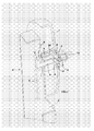
- fig. 1 is a perspective exploded view of the central portion of a handwheel according to the invention and of the locking means characterising it;
- fig. 2 is a perspective view of the handwheel of fig. 1, with some parts of the assembly removed, mounted onto a wall of a sliding cupboard, in a working position;
- fig. 3 is a perspective view similar to that of fig. 2 with the handwheel in a locking position.
- the manoeuvring handwheel 1 according to the invention - represented as a simple disc handwheel but which might be any other type of handwheel - is mounted rotating with the shaft 6, with which the bottom 5 of the handwheel is integral (in a known manner).
- the handwheel 1 is associated to a structure S (fig. 1) to carry out the control or the adjustment for which it is intended.
- the structure S is the side wall of a sliding cupboard A, which the handwheel 1 is associated to.
- the manoeuvring shaft 6 controls, in a known manner, through a gear wheel and a chain drive T, the movements of said cupboard A on the rails of the sliding filing system.
- the handwheel 1 incorporates in the middle a mushroom-shaped element 2 projecting outwards, which can be comfortably gripped with one hand.
- the element 2 is mounted sliding, according to the axis of rotation of the handwheel shaft 6.
- the mushroom-shaped element 2 carries inside two pins 3, protruding parallel to the shaft 6 and diametrically opposite on either side of said shaft 6.
- Said pins 3 are intended to engage in holes 5a provided therefor on the bottom 5 of the seat 4 provided for the mushroom-shaped element 2 in the middle of the handwheel 1.
- each hole 7 is paired with another hole 7 in a diametrically opposite position.
- the distance between the centres of said opposite holes is equal to that between the two pins 3 of the mushroom-shaped element 2 and therefore there are always two holes 7 in different angular positions, capable of receiving said pins 3.
- a key lock 8 incorporated in the mushroom-shaped element 2.
- This key lock 8, which may be operated acting on a key 10, comprises a short arm 9 projecting perpendicularly to the axis of shaft 6; with said arm 9 cooperates a talon 11, obtained in a single piece with - and rising from - the bottom 5 of the seat 4.
- this locking can be made stable acting onto the key 10, which causes the short arm 9 to engage under the talon 11 (position in fig. 3), so as to prevent further axial movements of the element 2 and therefore the undesired disengagement of the pins 3 from the holes 7.
- the opportunity to remove the key 10 represents a further element of safety.
- Figs. 2 and 3 show very clearly the operation of the handwheel with locking means according to the invention, when it is mounted on the side wall S of a sliding cupboard A, fig. 2 showing the working position and fig. 3 the locking position of the handwheel.
- the operator can rotate the handwheel 1, thereby opening a space between the cupboards, to access the files or the part thereof he is allowed to access by means of said key.
- the operator Before walking in the space between the cupboards for his activities, the operator, with a modest pressure, lowers the mushroom-shaped element 2 and rotates the key 10.
- the pins 3 thus engage the holes 7 on the side wall of the cupboard A and the key lock 8 causes the short arm 9 to rotate engaging with the talon 11; in this way the pins 3 cannot be disengaged from the holes 7 without acting on the key (which is normally removed by the operator who locks the handwheel). Further handling of one or more of the sliding cupboards (and also of all the cupboards) by any other operator can thereby be prevented.
- the operator inserts again the key 10 into the barrel of the key lock 8, rotates the short arm 9 disengaging it from the talon 11 and can, at this point, lift again the mushroom-shaped element 2; the cupboard or a group of cupboards or all the cupboards are thus again available for everybody.
- the operator "in charge”, after having locked the sliding cupboard, can lower the mushroom-shaped element equipped with the key into the seat of the handwheel 1 mounted on the sliding cupboard A, locking the same (or a part thereof, if groups of cupboards with different degrees of confidentiality are provided).
- the short arm 9 of the key lock 8 is driven to engage under the talon 11 thereby effecting a final locking of the cupboard.
- the operator can remove and keep the key, thereby ensuring that nobody can open groups of cupboards or all the cupboards and consequently that strangers or unauthorised persons can access the files or areas thereof outside working hours and until his next intervention.
- the locking system with a key lock can be used on a single handwheel, on all the handwheels of the cupboards of a sliding filing system or on a part thereof, according to the desired degree of security and confidentiality of the documents kept in the corresponding cupboards.
- the handwheel can be a spoke handwheel instead of a disc handwheel, with or without manoeuvring handle;
- the locking means can be mounted on the handwheel in a different position from the illustrated central one (which position, however, appears to be the most functional);
- the mushroom-shaped element can comprise a different number of locking pins, whose shape can vary. All these variants are naturally fully entitled to be included in the scope of protection of the present invention.
Landscapes
- Physics & Mathematics (AREA)
- General Physics & Mathematics (AREA)
- Engineering & Computer Science (AREA)
- Automation & Control Theory (AREA)
- Lock And Its Accessories (AREA)
- Power Steering Mechanism (AREA)
- Rehabilitation Tools (AREA)
- Golf Clubs (AREA)
- Casings For Electric Apparatus (AREA)
Applications Claiming Priority (2)
| Application Number | Priority Date | Filing Date | Title |
|---|---|---|---|
| ITMI20030335U | 2003-07-17 | ||
| IT000335U ITMI20030335U1 (it) | 2003-07-17 | 2003-07-17 | Volantino di manovra incorporante mezzi di blocco |
Publications (2)
| Publication Number | Publication Date |
|---|---|
| EP1498048A1 true EP1498048A1 (de) | 2005-01-19 |
| EP1498048B1 EP1498048B1 (de) | 2010-01-13 |
Family
ID=30012610
Family Applications (1)
| Application Number | Title | Priority Date | Filing Date |
|---|---|---|---|
| EP20040102898 Expired - Lifetime EP1498048B1 (de) | 2003-07-17 | 2004-06-23 | Betätigungshandrad mit mit Verriegelungsmittel |
Country Status (4)
| Country | Link |
|---|---|
| US (1) | US7155947B2 (de) |
| EP (1) | EP1498048B1 (de) |
| DE (1) | DE602004025070D1 (de) |
| IT (1) | ITMI20030335U1 (de) |
Cited By (2)
| Publication number | Priority date | Publication date | Assignee | Title |
|---|---|---|---|---|
| EP2050357A3 (de) * | 2007-10-18 | 2011-04-13 | Boteco S.p.A. | Betriebshandrad mit Sperrvorrichtung, insbesondere zum Betreiben von Handrädern an Rollenschränken |
| CN101673125B (zh) * | 2008-09-11 | 2012-07-04 | 宝元数控精密股份有限公司 | 磁性手轮 |
Families Citing this family (3)
| Publication number | Priority date | Publication date | Assignee | Title |
|---|---|---|---|---|
| US8056431B2 (en) * | 2008-09-08 | 2011-11-15 | Stanley Ackerman | Self-locking gear |
| US8720237B2 (en) * | 2011-10-19 | 2014-05-13 | Daws Manufacturing Company, Inc. | Rotary latch |
| US9260890B2 (en) | 2014-05-13 | 2016-02-16 | Daws Manufacturing Co., Inc. | Latch mechanism |
Citations (5)
| Publication number | Priority date | Publication date | Assignee | Title |
|---|---|---|---|---|
| US4256355A (en) * | 1976-12-22 | 1981-03-17 | Elecompack Company Ltd. | Locking and unlocking device for manually movable wheeled storage rack or the like |
| US4527680A (en) * | 1982-04-10 | 1985-07-09 | Yuji Sato | Locking device for movable storage rack |
| DE3533461A1 (de) * | 1985-09-19 | 1987-03-26 | Rexroth Mannesmann Gmbh | Drehknopf |
| US4723569A (en) * | 1985-12-09 | 1988-02-09 | Ellis (Colchester) Limited | Lock mechanisms |
| US5148754A (en) * | 1991-03-11 | 1992-09-22 | Tab Products Company | Carriage lock for a mobile storage system with rotatable actuator knob |
Family Cites Families (17)
| Publication number | Priority date | Publication date | Assignee | Title |
|---|---|---|---|---|
| US1076835A (en) * | 1912-04-29 | 1913-10-28 | Internat Locking Device Company | Locking device. |
| US1409429A (en) * | 1920-12-29 | 1922-03-14 | Tanski Stanly | Lock |
| US1539446A (en) * | 1921-06-22 | 1925-05-26 | Vincent Frederick | Steering-wheel lock |
| US1574321A (en) * | 1921-12-20 | 1926-02-23 | Vincent Frederick | Steering wheel |
| US1558637A (en) * | 1923-02-23 | 1925-10-27 | Louis R Ruthenburg | Lock for steering wheels |
| US1707458A (en) * | 1925-09-08 | 1929-04-02 | Standard Disk Wheel Company | Rim lock and operating means therefor |
| US1890896A (en) * | 1932-01-22 | 1932-12-13 | Barr William | Lockable regulating device |
| US3877261A (en) * | 1973-03-12 | 1975-04-15 | Packaging Tech Inc | Keyed fixed door lock |
| JPS542179Y2 (de) * | 1976-02-23 | 1979-01-30 | ||
| US4565078A (en) * | 1983-03-04 | 1986-01-21 | Solomon Martin D | Lock assembly |
| US4523794A (en) * | 1983-07-15 | 1985-06-18 | Spacesaver Corporation | Lock for manual mobile storage system |
| US5133265A (en) * | 1991-04-08 | 1992-07-28 | Tab Products Company | Visual indicator with aligning ridges for indicating the status of a carriage lock for a mobile storage system having a rotatable lock actuator knob |
| US5634358A (en) * | 1994-03-15 | 1997-06-03 | Fort Lock Corporation | Motorcycle ignition switch and steering lock |
| US5901590A (en) * | 1997-11-24 | 1999-05-11 | Lai; Chin-I | Interior door lock assembly with a safety device |
| US6178789B1 (en) * | 1999-03-30 | 2001-01-30 | Kason Industries, Inc. | Convertible cylinder lock |
| CA2333810A1 (en) * | 2000-02-29 | 2001-08-29 | Spacesaver Corporation | Torque limiting mechanism for a mechanical assist mobile storage system |
| US6843084B2 (en) * | 2001-05-30 | 2005-01-18 | Dave Porter | Storage compartment security system |
-
2003
- 2003-07-17 IT IT000335U patent/ITMI20030335U1/it unknown
-
2004
- 2004-06-18 US US10/871,953 patent/US7155947B2/en not_active Expired - Lifetime
- 2004-06-23 EP EP20040102898 patent/EP1498048B1/de not_active Expired - Lifetime
- 2004-06-23 DE DE200460025070 patent/DE602004025070D1/de not_active Expired - Lifetime
Patent Citations (5)
| Publication number | Priority date | Publication date | Assignee | Title |
|---|---|---|---|---|
| US4256355A (en) * | 1976-12-22 | 1981-03-17 | Elecompack Company Ltd. | Locking and unlocking device for manually movable wheeled storage rack or the like |
| US4527680A (en) * | 1982-04-10 | 1985-07-09 | Yuji Sato | Locking device for movable storage rack |
| DE3533461A1 (de) * | 1985-09-19 | 1987-03-26 | Rexroth Mannesmann Gmbh | Drehknopf |
| US4723569A (en) * | 1985-12-09 | 1988-02-09 | Ellis (Colchester) Limited | Lock mechanisms |
| US5148754A (en) * | 1991-03-11 | 1992-09-22 | Tab Products Company | Carriage lock for a mobile storage system with rotatable actuator knob |
Cited By (2)
| Publication number | Priority date | Publication date | Assignee | Title |
|---|---|---|---|---|
| EP2050357A3 (de) * | 2007-10-18 | 2011-04-13 | Boteco S.p.A. | Betriebshandrad mit Sperrvorrichtung, insbesondere zum Betreiben von Handrädern an Rollenschränken |
| CN101673125B (zh) * | 2008-09-11 | 2012-07-04 | 宝元数控精密股份有限公司 | 磁性手轮 |
Also Published As
| Publication number | Publication date |
|---|---|
| ITMI20030335U1 (it) | 2005-01-18 |
| DE602004025070D1 (de) | 2010-03-04 |
| US20050023845A1 (en) | 2005-02-03 |
| EP1498048B1 (de) | 2010-01-13 |
| US7155947B2 (en) | 2007-01-02 |
| ITMI20030335V0 (it) | 2003-07-17 |
Similar Documents
| Publication | Publication Date | Title |
|---|---|---|
| US7946141B2 (en) | Self-scrambling combination lock | |
| US9464460B2 (en) | Padlock with fully integrated dual locking mechanism with a lost code defining system | |
| US5265453A (en) | Cylinder lock | |
| DE69815655T2 (de) | Drucktastenschloss | |
| US6718803B2 (en) | Combination lock | |
| EP1837466B1 (de) | Schloss | |
| US4615191A (en) | Barrel combination lock | |
| US4998423A (en) | Ring shaped hanging lock with replaceable core | |
| CA2674105C (en) | Combination padlock | |
| US3541819A (en) | Tamper-proof axial tumbler lock | |
| US4370875A (en) | Slipping cylinder lock | |
| US5133265A (en) | Visual indicator with aligning ridges for indicating the status of a carriage lock for a mobile storage system having a rotatable lock actuator knob | |
| TWI565866B (zh) | 鎖心 | |
| AU710645B3 (en) | Pad lock with reliable change of code number | |
| CA3028650C (en) | Blade mounting and removal tool, system, and product slicer | |
| EP1498048B1 (de) | Betätigungshandrad mit mit Verriegelungsmittel | |
| US20200318390A1 (en) | Combination lock | |
| US4341099A (en) | Code changing system for combination padlocks | |
| EP0763638A1 (de) | Betätigungshandhabe | |
| US5592837A (en) | Pick resistant lock | |
| US20120174636A1 (en) | Spin-and-click combination dial lock assembly | |
| GB2254103A (en) | Locking mechanism for a valve | |
| CA2858909C (en) | Combination locks with improved code-changing features | |
| US6889460B1 (en) | Quick tactile release lock | |
| US2000111A (en) | Keyless lock mechanism |
Legal Events
| Date | Code | Title | Description |
|---|---|---|---|
| PUAI | Public reference made under article 153(3) epc to a published international application that has entered the european phase |
Free format text: ORIGINAL CODE: 0009012 |
|
| AK | Designated contracting states |
Kind code of ref document: A1 Designated state(s): AT BE BG CH CY CZ DE DK EE ES FI FR GB GR HU IE IT LI LU MC NL PL PT RO SE SI SK TR |
|
| AX | Request for extension of the european patent |
Extension state: AL HR LT LV MK |
|
| 17P | Request for examination filed |
Effective date: 20050711 |
|
| AKX | Designation fees paid |
Designated state(s): DE FR GB |
|
| RAP1 | Party data changed (applicant data changed or rights of an application transferred) |
Owner name: ELESA S.P.A. |
|
| GRAP | Despatch of communication of intention to grant a patent |
Free format text: ORIGINAL CODE: EPIDOSNIGR1 |
|
| GRAS | Grant fee paid |
Free format text: ORIGINAL CODE: EPIDOSNIGR3 |
|
| GRAA | (expected) grant |
Free format text: ORIGINAL CODE: 0009210 |
|
| AK | Designated contracting states |
Kind code of ref document: B1 Designated state(s): DE FR GB |
|
| REG | Reference to a national code |
Ref country code: GB Ref legal event code: FG4D |
|
| REF | Corresponds to: |
Ref document number: 602004025070 Country of ref document: DE Date of ref document: 20100304 Kind code of ref document: P |
|
| PLBE | No opposition filed within time limit |
Free format text: ORIGINAL CODE: 0009261 |
|
| STAA | Information on the status of an ep patent application or granted ep patent |
Free format text: STATUS: NO OPPOSITION FILED WITHIN TIME LIMIT |
|
| 26N | No opposition filed |
Effective date: 20101014 |
|
| REG | Reference to a national code |
Ref country code: FR Ref legal event code: PLFP Year of fee payment: 13 |
|
| REG | Reference to a national code |
Ref country code: FR Ref legal event code: PLFP Year of fee payment: 14 |
|
| REG | Reference to a national code |
Ref country code: FR Ref legal event code: PLFP Year of fee payment: 15 |
|
| P01 | Opt-out of the competence of the unified patent court (upc) registered |
Effective date: 20230527 |
|
| PGFP | Annual fee paid to national office [announced via postgrant information from national office to epo] |
Ref country code: FR Payment date: 20230419 Year of fee payment: 20 Ref country code: DE Payment date: 20230419 Year of fee payment: 20 |
|
| PGFP | Annual fee paid to national office [announced via postgrant information from national office to epo] |
Ref country code: GB Payment date: 20230419 Year of fee payment: 20 |
|
| REG | Reference to a national code |
Ref country code: DE Ref legal event code: R071 Ref document number: 602004025070 Country of ref document: DE |
|
| PG25 | Lapsed in a contracting state [announced via postgrant information from national office to epo] |
Ref country code: GB Free format text: LAPSE BECAUSE OF EXPIRATION OF PROTECTION Effective date: 20240622 |
|
| REG | Reference to a national code |
Ref country code: GB Ref legal event code: PE20 Expiry date: 20240622 |
|
| PG25 | Lapsed in a contracting state [announced via postgrant information from national office to epo] |
Ref country code: GB Free format text: LAPSE BECAUSE OF EXPIRATION OF PROTECTION Effective date: 20240622 |