EP1498054A2 - Cintre pour vêtements ajustable - Google Patents
Cintre pour vêtements ajustable Download PDFInfo
- Publication number
- EP1498054A2 EP1498054A2 EP04103251A EP04103251A EP1498054A2 EP 1498054 A2 EP1498054 A2 EP 1498054A2 EP 04103251 A EP04103251 A EP 04103251A EP 04103251 A EP04103251 A EP 04103251A EP 1498054 A2 EP1498054 A2 EP 1498054A2
- Authority
- EP
- European Patent Office
- Prior art keywords
- arms
- adjustable
- clothes hanger
- arm
- main
- Prior art date
- Legal status (The legal status is an assumption and is not a legal conclusion. Google has not performed a legal analysis and makes no representation as to the accuracy of the status listed.)
- Withdrawn
Links
- 238000010276 construction Methods 0.000 description 3
- 230000037303 wrinkles Effects 0.000 description 3
- 230000004048 modification Effects 0.000 description 2
- 238000012986 modification Methods 0.000 description 2
- 239000000853 adhesive Substances 0.000 description 1
- 230000001070 adhesive effect Effects 0.000 description 1
- 230000004075 alteration Effects 0.000 description 1
- 230000001153 anti-wrinkle effect Effects 0.000 description 1
- 230000015572 biosynthetic process Effects 0.000 description 1
- 239000004744 fabric Substances 0.000 description 1
- 239000003292 glue Substances 0.000 description 1
- 239000002991 molded plastic Substances 0.000 description 1
- 239000004033 plastic Substances 0.000 description 1
Images

Classifications
-
- A—HUMAN NECESSITIES
- A47—FURNITURE; DOMESTIC ARTICLES OR APPLIANCES; COFFEE MILLS; SPICE MILLS; SUCTION CLEANERS IN GENERAL
- A47G—HOUSEHOLD OR TABLE EQUIPMENT
- A47G25/00—Household implements used in connection with wearing apparel; Dress, hat or umbrella holders
- A47G25/14—Clothing hangers, e.g. suit hangers
- A47G25/20—Clothing hangers, e.g. suit hangers with devices for preserving the shape of the clothes
-
- A—HUMAN NECESSITIES
- A47—FURNITURE; DOMESTIC ARTICLES OR APPLIANCES; COFFEE MILLS; SPICE MILLS; SUCTION CLEANERS IN GENERAL
- A47G—HOUSEHOLD OR TABLE EQUIPMENT
- A47G25/00—Household implements used in connection with wearing apparel; Dress, hat or umbrella holders
- A47G25/14—Clothing hangers, e.g. suit hangers
- A47G25/44—Slidable hangers ; Adjustable hangers
- A47G25/441—Slidable hangers ; Adjustable hangers having adjustable width
- A47G25/442—Slidable hangers ; Adjustable hangers having adjustable width to support shouldered garments
-
- A—HUMAN NECESSITIES
- A47—FURNITURE; DOMESTIC ARTICLES OR APPLIANCES; COFFEE MILLS; SPICE MILLS; SUCTION CLEANERS IN GENERAL
- A47G—HOUSEHOLD OR TABLE EQUIPMENT
- A47G25/00—Household implements used in connection with wearing apparel; Dress, hat or umbrella holders
- A47G25/14—Clothing hangers, e.g. suit hangers
- A47G25/40—Collapsible hangers
-
- A—HUMAN NECESSITIES
- A47—FURNITURE; DOMESTIC ARTICLES OR APPLIANCES; COFFEE MILLS; SPICE MILLS; SUCTION CLEANERS IN GENERAL
- A47G—HOUSEHOLD OR TABLE EQUIPMENT
- A47G25/00—Household implements used in connection with wearing apparel; Dress, hat or umbrella holders
- A47G25/14—Clothing hangers, e.g. suit hangers
- A47G25/44—Slidable hangers ; Adjustable hangers
Definitions
- the present invention relates to clothes hangers, and more particularly, to an adjustable clothes hanger with improved anti-wrinkle performance.
- Clothes hangers of fixed construction have the disadvantage that clothing of different styles and shapes and sizes do not all fit on the hanger equally well. As a result, clothes which are misfit to the shape or size of the hanger, hang in a deformed manner which causes wrinkling and misshaping of the cloth.
- the following are exemplary of the prior art; U.S. Pat. Nos. 923,786; 2,436,314, 2,494,711; 2,504,562; 2,679,958, 2,716,512; 2,900,117; 2,944,711; 3,039,662; 3,874,572 and 4,717,053 and United Kingdom Patent 887,020.
- U.S. Patent No. 5,085,358 to Lam discloses a clothes hanger of the type in which the hanger arms for supporting clothing are adjustable in length.
- the clothes hanger includes elongated main arms each having a top side. Locator elements comprising a series of recesses are formed in the bottom surface extending along the length of each main arm.
- the clothes hanger also has adjustable arms that have top walls and that define channels for slidably and pivotally interfitting with the elongated main arms.
- top sides of the main arms and the top walls of the adjustable arms are not continuous and flat, in that there is a ridge that is formed where the top sides meet the top walls. Such a ridge may cause clothes that are hung on this type of hanger to form a wrinkle. Accordingly, it would be an improvement to provide an adjustable hanger that has a more continuous and flat top side to prevent wrinkling of clothes.
- a clothes hanger includes an attachment member and first and second main arms extending from the attachment member. Each main arm forms an adjustment element.
- the clothes hanger also includes first and second adjustable arms and first and second cover arms.
- the first and second adjustable arms are each movably connected with one respective main arm.
- Each adjustable arm includes a locator element engageable with a respective adjustment element.
- the first and second cover arms are each connected with a respective adjustable arm and a respective main arm.
- a clothes hanger includes an attachment member and first and second main arms extending from the attachment member. Each main arm forms an adjustment element and a primary track.
- the clothes hanger also includes first and second adjustable arms each movably and pivotally connected with one respective main arm.
- Each adjustable arm includes a locator element engageable with a respective adjustment element and a primary sliding member received in a respective primary track.
- a clothes hanger includes a first main arm connected with a second main arm. Each main arm forms an adjustment element and a primary track.
- the clothes hanger also includes first and second adjustable arms each movably and pivotally connected with one respective main arm. Each adjustable arm includes a locator element engageable with a respective adjustment element and a primary sliding member received in each primary track.
- the clothes hanger preferably comprises a junction connected with the first and second main arms.
- the clothes hanger preferably comprises first and second cover arms each connected with a respective adjustable arm and a respective main arm.
- the first and second cover arms of the clothes hanger are each pivotally connected with a respective main arm and movably connected with a respective adjustable arm.
- each adjustable arm forms a secondary track, and the first and second cover arms each includes a secondary sliding member each movably connected within a respective secondary track.
- the clothes hanger preferably comprises a cross bar connected between the first and second main arms.
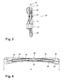
- FIG. 1 is a front perspective view of an adjustable clothes hanger, in accordance with one embodiment.
- FIG. 2 is a front view of the adjustable clothes hanger shown in FIG. 1, in accordance with one embodiment.
- FIG. 3 is a side perspective view of the adjustable clothes hanger shown in FIG. 1, in accordance with one embodiment.
- FIG. 4 is a top view of the adjustable clothes hanger shown in FIG. 1, in accordance with one embodiment.
- the present invention relates to an adjustable clothes hanger for hanging garments.
- the clothes hanger includes first and second main arms connected with each other, wherein each main arm forms an adjustment element.
- each main arm forms a primary track as well.
- the clothes hanger also includes first and second adjustable arms each movably and pivotally connected with one respective main arm, wherein each adjustable arm includes a locator element engageable with a respective adjustment element.
- each adjustable arm includes a primary sliding member received in each primary track.
- the adjustable clothes hanger includes cover arms to provide a continuous surface for the garments to rest upon, and therefore reducing the amount of wrinkles in the garments once the garments have been placed on the adjustable clothes hanger.
- an adjustable clothes hanger 20 in accordance with the present invention includes an attachment member 24 and first and second main arms 28, 30 each having an inner end 33 and an outer end 34.
- the adjustable clothes hanger 20 also includes cover arms 52, 54, as described below.
- the main arm inner ends 33 are mounted proximate to one another as by a junction 35 with the main arms 28, 30 diverging symmetrically therefrom by an included angle of preferably between 120 and 170 degrees, and more preferably between 140 and 160 degrees.
- the attachment member 24 is placed centrally atop the junction 35.
- the attachment member 24 may include any device or member that can be used to attach the clothes hanger 20 to another member, including: a mechanical device, such a hook 14, a hook and loop type fastener such as VELCROTM, a snap-fit member, a loop, and a clamp; an adhesive device such as glue; and other such devices.
- a mechanical device such as a hook 14, a hook and loop type fastener such as VELCROTM, a snap-fit member, a loop, and a clamp
- an adhesive device such as glue
- Each main arm 28, 30 forms a number of sides.
- the main arms 28, 30 form four sides, a top side 72, a bottom side 74, a forward side 76, and a rear side 78.
- the four sides may be generally rectangular in cross section, wherein the forward and rear sides 76, 78 are generally parallel and the top and bottom sides 72, 74 are also generally parallel.
- Each main arm 28, 30 forms an adjustment element 32 that preferably includes a series of recesses 37 formed in a side, such as the top side 72, extending along a length of each main arms 28, 30.
- a hook 84 which extends inwardly.
- a cross bar 80 extends generally between the outer ends 34, being attached thereto by attachment members 81.
- the attachment members 81 removably attach the cross bar 80 each main arm 28, 30.
- the attachment member 81 may be snap-fit members 82, or any other such devices, that may be used to removably attach the cross bar 80.
- each main arm 28, 30 also forms a primary track 36 for receiving a primary sliding member 60 of an adjustable arm 40, 42, as described below.
- the forward side 76, rear side 78, top side 72, and bottom side 74 extend along the length of each main arm 28, 30 between the inner end 33 and the outer end 34 except for interruption of the top side 72 by interposition of the recesses 37 as now to be described. While the recesses 37 in the current embodiment are formed on the top side 72, the recesses 37 may be formed on any side 72, 74, 76, 78 of the main arms 28, 30. In one embodiment, the recesses 37 are formed in the primary track 36. Forming recesses 37 in the primary track allows the adjustable arms 40, 42 to lift out of the adjustment element 32 without having to pivot.
- the recesses 37 of the illustrated embodiment are upwardly open formed by walls having three segments, opposed lateral segments 37a and 37b and an upper segment 37c.
- the size of the recesses 37 and in particular the space between lateral segments 37a and 37b, as will be apparent, is based on a determination of how finely it is desired to adjust the length of the hanger arms, that is, the effective hanger length provided by the combination of the main arms 28, 30 and adjustable arms 40, 42 connected with the main arms 28, 30, as described below. Reducing the distance between recesses 37 will allow finer adjustment and increasing the distance between recesses 37 will allow coarser adjustment.
- the length of the series of recesses 37 between the inner ends 33 and outer ends 34 of the main arms 28, 30 is determined by the length of the adjustable arms 40, 42 and the desired fully extended effective length of the clothes hanger 20.
- the depth of the recesses 37 is chosen to provide secure positioning as well as straight alignment of the adjustable arms 40, 42 on the main arms 28, 30.
- each adjustable arm 40, 42 includes a locator element 48 engageable with a respective adjustment element 32, and more particularly, engageable with a respective recess 37, as illustrated in FIG. 2.
- the adjustable arms 40, 42 have a body 46 preferably having a U-shaped cross section that is downwardly open, formed from a front side wall 49 and a rear side wall 50 and a top wall 51, which present opposed inner side surfaces and a top inner surface.
- Top wall 51 defines a secondary track 64 for slidably and pivotally interfitting with a secondary sliding member 68 of each cover arm 52, 54, as described below.
- the adjustable arms 40, 42 have the locator element 48 comprising a protrusion 53 formed at the top inner surface 97 of the adjustable arms 40, 42.
- the adjustable arms 40, 42 include a primary sliding member 60 each movably connected with a respective primary track 36. More preferably, the primary sliding member 60 is movably and pivotally connected with a respective primary track 36 of one main arm 28, 30. In this manner, the primary sliding member 60 allows for sliding and pivoting one of the adjustable arms 40, 42 such that the respective locator element 48 may move in and out of engagement with the respective adjustment element 32.
- the adjustable arms 40, 42 are also equipped with a shoulder pad 47 which is shaped to support the shoulder of an item of clothing.
- the shoulder pad 47 is integrally formed with each adjustable arm 40, 42 at an outer end thereof.
- the adjustable arms 40, 42 are preferably formed of molded rigid plastic, as are the main arms 28, 30, the attachment member 24, the junction 35, and the cover arms 52, 54. While in the above described structure, the primary sliding member 60 is pressed into holes formed in the body 46 of the adjustable arms 40, 42, the entire adjustable arms 40, 42, including the primary sliding member 60, could be constructed of one piece of molded plastic. In order to enable assembly of the one piece adjustable arms 40, 42 of this configuration onto the main arms 28, 30, the primary track 36 formed in each main arm 28, 30 would have to be open at some point along the length of the primary track 36, so as to allow the primary sliding member 60 to slide directly into the primary track 36.
- the first and second cover arms 52, 54 are each pivotally connected with a respective main arm 28, 30 and movably connected with a respective adjustable arm 40, 42.
- the cover arms 52, 54 cover at least a portion of the top side 72 of each main arm 28, 30 and at least a portion of the top wall 51 of each adjustable arm 40, 42 to provide a continuous surface 55 for a garment to rest upon, and therefore reducing the amount of, or preventing the formation of, wrinkles in a garment once the garment has been placed on the adjustable clothes hanger 20.
- the cover arms 52, 54 also cover a portion of the secondary track 64 on each adjustable arm 40, 42.
- the cover arms 52, 54 include the secondary sliding member 68 each movably connected with a respective secondary track 64.
- the secondary sliding member 68 is movably and pivotally connected with a respective secondary track 64 of one adjustable arm 40, 42.
- the secondary sliding member 68 allows for sliding and pivoting one of the cover arms 52, 54 relative to a respective adjustable arm 40, 42.
- the cover arms 52, 54 include a pivoting member 44 that is pivotally connected with a respective main arm 28, 30.
- the pivoting member 44 may be one of a variety of devices which allow for pivoting between two elements, such as, a pin, a snap-fit arrangement, a wheel, a cylinder, and a gear.
- the adjustable arms 40, 42 extend beyond the outer end 34 of the main arms 28, 30 thereby providing an extended effective length "C" of the clothes hanger 20 for supporting an item of clothing.
- the adjustable arms 40, 42 are each held in place by co-action of the primary sliding member 60, the locator element 48 and the adjustment element 32, which prevent longitudinal movement and downward pivoting of the adjustable arms 40, 42.
- Contact of the top wall 51 and, more specifically, the top inner surface 97 with the top side 72 of the main arms 28, 30 prevents downward pivoting.
- Contact of the front side wall 49 and the rear side wall 50 with the forward side 76 and the rear side 78 respectively of the main arms 28, 30 prevents twisting of the adjustable arms 40, 42.
- the adjustable arms 40, 42 are upward pivoted as shown in FIGS. 1-4 so that the locator element 48 pivots out of the adjustment element 32.
- the adjustable arms 40, 42, and more specifically, the primary sliding member 60 can slide along the main arms 28, 30, and more specifically, the primary track 36, to a new selected point, and can then be down-pivoted so that the locator element 48 rests in a new selected recess 37.
- the first and second cover arms 52, 54 each pivot with respect to a respective main arm 28, 30 and move or slide with respect to a respective adjustable arm 40, 42 so that when the adjustable arms 40, 42 are moved from one point to another, the cover arms are able to still cover at least a portion of the top side 72 of each main arm 28, 30 and at least a portion of the top wall 51 of each adjustable arm 40, 42 to provide a continuous surface 55 for a garment to rest upon.
- the construction just described requires at least one separately constructed part in order to assemble the adjustable arms 40, 42 onto the clothes hanger 20.
- the primary sliding member 60 would be made separately and pressed into holes 61 in the front side walls 49 and rear side wall 50 after mounting of the adjustable arms 40, 42 onto the main arms 28, 30.
- a number of alternative constructions are possible, including allowing the attachment member 24, the junction 35, and the main arms 28, 30 to be made of one piece.
Landscapes
- Holders For Apparel And Elements Relating To Apparel (AREA)
Applications Claiming Priority (2)
| Application Number | Priority Date | Filing Date | Title |
|---|---|---|---|
| US622161 | 2003-07-17 | ||
| US10/622,161 US6964360B2 (en) | 2003-07-17 | 2003-07-17 | Adjustable clothes hanger |
Publications (2)
| Publication Number | Publication Date |
|---|---|
| EP1498054A2 true EP1498054A2 (fr) | 2005-01-19 |
| EP1498054A3 EP1498054A3 (fr) | 2005-04-13 |
Family
ID=33477125
Family Applications (1)
| Application Number | Title | Priority Date | Filing Date |
|---|---|---|---|
| EP04103251A Withdrawn EP1498054A3 (fr) | 2003-07-17 | 2004-07-08 | Cintre pour vêtements ajustable |
Country Status (8)
| Country | Link |
|---|---|
| US (1) | US6964360B2 (fr) |
| EP (1) | EP1498054A3 (fr) |
| JP (1) | JP2005034643A (fr) |
| KR (1) | KR20050009222A (fr) |
| CN (1) | CN1575701A (fr) |
| AU (1) | AU2004202910A1 (fr) |
| BR (1) | BRPI0402736A (fr) |
| MX (1) | MXPA04006941A (fr) |
Cited By (2)
| Publication number | Priority date | Publication date | Assignee | Title |
|---|---|---|---|---|
| DE202007010741U1 (de) | 2007-08-02 | 2008-12-11 | Schwan-Stabilo Cosmetics Gmbh & Co. Kg | Vorrichtung zum Speichern und Auftragen eines flüssigen, gelartigen oder pastösen Produkts |
| WO2020092685A1 (fr) * | 2018-10-31 | 2020-05-07 | Lou Hansell, LLC | Cintre |
Families Citing this family (25)
| Publication number | Priority date | Publication date | Assignee | Title |
|---|---|---|---|---|
| JP3836103B2 (ja) * | 2003-11-28 | 2006-10-18 | マルソー産業株式会社 | 衣料用ハンガー |
| US7222761B1 (en) * | 2004-02-19 | 2007-05-29 | Andrea Licwinko | Hanger apparatus |
| US7644844B1 (en) | 2006-06-12 | 2010-01-12 | Bonner James D | Clothes hanger |
| US8028868B2 (en) * | 2008-01-25 | 2011-10-04 | Ingenious Designs, Llc | Garment arrangement system |
| USD584518S1 (en) | 2008-01-25 | 2009-01-13 | Ingenious Designs Llc | Garment bar |
| US20100299954A1 (en) | 2009-06-01 | 2010-12-02 | Brian Joseph Roselle | Fabric Refreshing Cabinet Device |
| US8931667B2 (en) * | 2008-09-24 | 2015-01-13 | The Procter & Gamble Company | Methods and apparatuses for dispensing fluids |
| MX2011010127A (es) * | 2009-03-27 | 2011-10-11 | Procter & Gamble | Sistema dosificador de fluidos para dispositivo de gabinete para renovar telas. |
| US9410281B2 (en) | 2009-05-01 | 2016-08-09 | Whirlpool Corporation | Fabric treating systems and accessories |
| WO2010141439A1 (fr) * | 2009-06-01 | 2010-12-09 | The Procter & Gamble Company | Dispositif d'armoire à rafraîchir les tissus de façon à augmenter la rigidité à la flexion |
| KR101333508B1 (ko) | 2009-06-01 | 2013-11-28 | 더 프록터 앤드 갬블 캄파니 | 수동적 열 관리 시스템을 포함하는 직물 재생 캐비닛 장치 |
| US8857678B1 (en) * | 2013-05-29 | 2014-10-14 | Yi-Ming Tseng | Hanger for supporting garment and device for enhancing use of hanger |
| US9186009B2 (en) | 2013-06-06 | 2015-11-17 | Erik Laibe | Hanger strap and shoulder covers |
| US9402495B2 (en) | 2013-06-18 | 2016-08-02 | Erik Laibe | Adjustable hanger |
| USD723810S1 (en) | 2013-10-02 | 2015-03-10 | Whirlpool Corporation | Hanger assembly |
| US20160166098A1 (en) * | 2014-12-13 | 2016-06-16 | Annie Varghese-Abraham | Clothing hanger with outfit organizer features |
| CN105411333B (zh) * | 2015-12-30 | 2018-02-16 | 周胡静 | 衣架 |
| US10786102B2 (en) * | 2016-03-03 | 2020-09-29 | Kyle L. Baltz | Single hand operated collapsing hanger |
| CN107280416A (zh) * | 2017-08-11 | 2017-10-24 | 安徽信息工程学院 | 一种可固定衣架 |
| US11478097B2 (en) * | 2018-09-07 | 2022-10-25 | Brian Curci | Collapsible hanger cover |
| US20200237130A1 (en) * | 2019-01-25 | 2020-07-30 | Jose Varelas | Adjustable clothes hanger assembly |
| USD1039845S1 (en) * | 2023-04-15 | 2024-08-27 | Zhiyong Zhou | Telescopic foldable clothes hanger |
| US12185855B2 (en) | 2023-05-19 | 2025-01-07 | Jack Whyte | Adjustable clothes hanger assembly |
| USD1073332S1 (en) * | 2023-06-20 | 2025-05-06 | Minjia Ye | Retractable hanger |
| TWI890586B (zh) * | 2024-09-11 | 2025-07-11 | 國立勤益科技大學 | 防風衣架 |
Citations (8)
| Publication number | Priority date | Publication date | Assignee | Title |
|---|---|---|---|---|
| US923786A (en) | 1907-03-23 | 1909-06-01 | Charles Linkins | Coat-hanger. |
| US2436314A (en) | 1945-11-10 | 1948-02-17 | Lesavoy Isadore Lawrence | Garment hanger |
| US2494711A (en) | 1946-06-28 | 1950-01-17 | Kusher Hyman | Garment hanger |
| US2504562A (en) | 1947-04-17 | 1950-04-18 | Cleo E Melcher | Coat hanger |
| US2679958A (en) | 1953-03-20 | 1954-06-01 | Massa Gerald | Garment hanger |
| US2716512A (en) | 1953-09-22 | 1955-08-30 | Henry L Needles | Adjustable coat hanger |
| US2900117A (en) | 1956-01-11 | 1959-08-18 | Veltry Dominick | Adjustable garment hanger |
| US2944711A (en) | 1959-05-25 | 1960-07-12 | Philip G Sage | Garment hanger structure |
Family Cites Families (8)
| Publication number | Priority date | Publication date | Assignee | Title |
|---|---|---|---|---|
| US2484711A (en) * | 1944-05-15 | 1949-10-11 | Walter Johnson | Coin-controlled switch |
| US2724533A (en) * | 1953-07-27 | 1955-11-22 | Hansen Clarence | Adjustable garment hanger |
| US2900711A (en) * | 1956-08-29 | 1959-08-25 | American Brake Shoe Co | Method of making brake shoes |
| US3039662A (en) * | 1959-01-22 | 1962-06-19 | Robert A Strong | Garment hanging means |
| US3874572A (en) * | 1972-10-13 | 1975-04-01 | Mary M Mcclenning | Collapsible hanger |
| US4717053A (en) * | 1987-02-19 | 1988-01-05 | Wang Kuo Ru | Extendible and foldable garment hanger |
| US5085358A (en) * | 1990-10-11 | 1992-02-04 | Lam Peter A | Adjustable clothes hanger |
| US5082152A (en) * | 1990-12-26 | 1992-01-21 | Chen Shing Huei | Garment hanger with adjustable clamping crossbar |
-
2003
- 2003-07-17 US US10/622,161 patent/US6964360B2/en not_active Expired - Fee Related
-
2004
- 2004-06-28 AU AU2004202910A patent/AU2004202910A1/en not_active Abandoned
- 2004-07-08 EP EP04103251A patent/EP1498054A3/fr not_active Withdrawn
- 2004-07-08 JP JP2004201624A patent/JP2005034643A/ja not_active Abandoned
- 2004-07-14 BR BR0402736-1A patent/BRPI0402736A/pt not_active Application Discontinuation
- 2004-07-15 MX MXPA04006941A patent/MXPA04006941A/es unknown
- 2004-07-16 CN CNA2004100699830A patent/CN1575701A/zh active Pending
- 2004-07-16 KR KR1020040055438A patent/KR20050009222A/ko not_active Withdrawn
Patent Citations (8)
| Publication number | Priority date | Publication date | Assignee | Title |
|---|---|---|---|---|
| US923786A (en) | 1907-03-23 | 1909-06-01 | Charles Linkins | Coat-hanger. |
| US2436314A (en) | 1945-11-10 | 1948-02-17 | Lesavoy Isadore Lawrence | Garment hanger |
| US2494711A (en) | 1946-06-28 | 1950-01-17 | Kusher Hyman | Garment hanger |
| US2504562A (en) | 1947-04-17 | 1950-04-18 | Cleo E Melcher | Coat hanger |
| US2679958A (en) | 1953-03-20 | 1954-06-01 | Massa Gerald | Garment hanger |
| US2716512A (en) | 1953-09-22 | 1955-08-30 | Henry L Needles | Adjustable coat hanger |
| US2900117A (en) | 1956-01-11 | 1959-08-18 | Veltry Dominick | Adjustable garment hanger |
| US2944711A (en) | 1959-05-25 | 1960-07-12 | Philip G Sage | Garment hanger structure |
Cited By (3)
| Publication number | Priority date | Publication date | Assignee | Title |
|---|---|---|---|---|
| DE202007010741U1 (de) | 2007-08-02 | 2008-12-11 | Schwan-Stabilo Cosmetics Gmbh & Co. Kg | Vorrichtung zum Speichern und Auftragen eines flüssigen, gelartigen oder pastösen Produkts |
| WO2020092685A1 (fr) * | 2018-10-31 | 2020-05-07 | Lou Hansell, LLC | Cintre |
| US11457757B2 (en) | 2018-10-31 | 2022-10-04 | Lou Hansell, LLC | Clothing hanger |
Also Published As
| Publication number | Publication date |
|---|---|
| US6964360B2 (en) | 2005-11-15 |
| MXPA04006941A (es) | 2005-04-21 |
| BRPI0402736A (pt) | 2005-03-29 |
| EP1498054A3 (fr) | 2005-04-13 |
| AU2004202910A1 (en) | 2005-02-03 |
| JP2005034643A (ja) | 2005-02-10 |
| US20050011917A1 (en) | 2005-01-20 |
| CN1575701A (zh) | 2005-02-09 |
| KR20050009222A (ko) | 2005-01-24 |
Similar Documents
| Publication | Publication Date | Title |
|---|---|---|
| US6964360B2 (en) | Adjustable clothes hanger | |
| US5085358A (en) | Adjustable clothes hanger | |
| US20180035774A1 (en) | Universal Arrangement for Suitcases Having Sliding Internal Frame to Hang Garment Hangers | |
| US6220489B1 (en) | Folding clothes hanger | |
| US20130320051A1 (en) | Garment hanger with adjustable shoulder section and non-slip crease free horizontal pants section | |
| US5950884A (en) | Suspender hanging assembly | |
| US20080257920A1 (en) | Adjustable arms for garment hanger | |
| KR200345248Y1 (ko) | 옷걸이 | |
| US20180184829A1 (en) | Garment Hanger | |
| US2514820A (en) | Clothes hanger | |
| US2504562A (en) | Coat hanger | |
| KR101045398B1 (ko) | 폭 조절이 가능한 바지 걸이 | |
| WO1986006600A1 (fr) | Cintre extensible | |
| CN201189063Y (zh) | 一种伸缩衣架 | |
| US3260427A (en) | Clothes hanger hold down clamp | |
| JP3238161U (ja) | ハンガーに着脱できる折り畳み式肩パッド | |
| US20200138219A1 (en) | Clothes Hangers and Clips Used Therewith | |
| US20060011672A1 (en) | Adjustable extension for a clothes hanger | |
| US2153551A (en) | Garment hanger | |
| US2491077A (en) | Clothes hanger | |
| JP2000333813A (ja) | 掛け皺防止手段を備えた衣服用ハンガーおよび掛け皺防止用アタッチメント | |
| US2849169A (en) | Safety dress hanger | |
| KR200419886Y1 (ko) | 철선옷걸이용 어깨받이 | |
| KR20160004006U (ko) | 길이 가변식 옷걸이 | |
| KR20240001825A (ko) | 옷걸이 |
Legal Events
| Date | Code | Title | Description |
|---|---|---|---|
| PUAI | Public reference made under article 153(3) epc to a published international application that has entered the european phase |
Free format text: ORIGINAL CODE: 0009012 |
|
| AK | Designated contracting states |
Kind code of ref document: A2 Designated state(s): AT BE BG CH CY CZ DE DK EE ES FI FR GB GR HU IE IT LI LU MC NL PL PT RO SE SI SK TR |
|
| AX | Request for extension of the european patent |
Extension state: AL HR LT LV MK |
|
| PUAL | Search report despatched |
Free format text: ORIGINAL CODE: 0009013 |
|
| AK | Designated contracting states |
Kind code of ref document: A3 Designated state(s): AT BE BG CH CY CZ DE DK EE ES FI FR GB GR HU IE IT LI LU MC NL PL PT RO SE SI SK TR |
|
| AX | Request for extension of the european patent |
Extension state: AL HR LT LV MK |
|
| 17P | Request for examination filed |
Effective date: 20051005 |
|
| AKX | Designation fees paid |
Designated state(s): DE FR GB IT SE |
|
| STAA | Information on the status of an ep patent application or granted ep patent |
Free format text: STATUS: THE APPLICATION IS DEEMED TO BE WITHDRAWN |
|
| 18D | Application deemed to be withdrawn |
Effective date: 20090203 |