EP1498086B1 - Vorrichtung zum Plazieren eines Kanals in Flüssigkeitsverbindung mit einem Zielgefäss - Google Patents
Vorrichtung zum Plazieren eines Kanals in Flüssigkeitsverbindung mit einem Zielgefäss Download PDFInfo
- Publication number
- EP1498086B1 EP1498086B1 EP04394044A EP04394044A EP1498086B1 EP 1498086 B1 EP1498086 B1 EP 1498086B1 EP 04394044 A EP04394044 A EP 04394044A EP 04394044 A EP04394044 A EP 04394044A EP 1498086 B1 EP1498086 B1 EP 1498086B1
- Authority
- EP
- European Patent Office
- Prior art keywords
- fistula device
- fistula
- elongate
- delivery
- sheath
- Prior art date
- Legal status (The legal status is an assumption and is not a legal conclusion. Google has not performed a legal analysis and makes no representation as to the accuracy of the status listed.)
- Expired - Lifetime
Links
- 206010016717 Fistula Diseases 0.000 title claims description 128
- 230000003890 fistula Effects 0.000 title claims description 128
- 238000004891 communication Methods 0.000 title claims description 9
- 239000012530 fluid Substances 0.000 title description 6
- 230000000149 penetrating effect Effects 0.000 claims description 16
- 210000005242 cardiac chamber Anatomy 0.000 claims description 10
- 238000004873 anchoring Methods 0.000 claims description 7
- 210000004351 coronary vessel Anatomy 0.000 description 26
- 230000003902 lesion Effects 0.000 description 21
- 210000004369 blood Anatomy 0.000 description 19
- 239000008280 blood Substances 0.000 description 19
- 238000000034 method Methods 0.000 description 18
- 210000004165 myocardium Anatomy 0.000 description 15
- 230000002861 ventricular Effects 0.000 description 13
- 206010012601 diabetes mellitus Diseases 0.000 description 12
- 238000010586 diagram Methods 0.000 description 12
- 210000001367 artery Anatomy 0.000 description 11
- 230000017531 blood circulation Effects 0.000 description 9
- 230000000452 restraining effect Effects 0.000 description 7
- 208000019622 heart disease Diseases 0.000 description 6
- 238000002399 angioplasty Methods 0.000 description 5
- 229940079593 drug Drugs 0.000 description 5
- 239000003814 drug Substances 0.000 description 5
- QVGXLLKOCUKJST-UHFFFAOYSA-N atomic oxygen Chemical compound [O] QVGXLLKOCUKJST-UHFFFAOYSA-N 0.000 description 4
- 230000008901 benefit Effects 0.000 description 4
- 210000004204 blood vessel Anatomy 0.000 description 4
- 210000002889 endothelial cell Anatomy 0.000 description 4
- HLXZNVUGXRDIFK-UHFFFAOYSA-N nickel titanium Chemical compound [Ti].[Ti].[Ti].[Ti].[Ti].[Ti].[Ti].[Ti].[Ti].[Ti].[Ti].[Ni].[Ni].[Ni].[Ni].[Ni].[Ni].[Ni].[Ni].[Ni].[Ni].[Ni].[Ni].[Ni].[Ni] HLXZNVUGXRDIFK-UHFFFAOYSA-N 0.000 description 4
- 229910001000 nickel titanium Inorganic materials 0.000 description 4
- 229910052760 oxygen Inorganic materials 0.000 description 4
- 239000001301 oxygen Substances 0.000 description 4
- 201000001320 Atherosclerosis Diseases 0.000 description 3
- 210000002808 connective tissue Anatomy 0.000 description 3
- 239000007943 implant Substances 0.000 description 3
- 210000005240 left ventricle Anatomy 0.000 description 3
- 238000011068 loading method Methods 0.000 description 3
- 238000001356 surgical procedure Methods 0.000 description 3
- 210000001519 tissue Anatomy 0.000 description 3
- 210000005166 vasculature Anatomy 0.000 description 3
- 206010002383 Angina Pectoris Diseases 0.000 description 2
- 210000000709 aorta Anatomy 0.000 description 2
- 230000003143 atherosclerotic effect Effects 0.000 description 2
- 230000015572 biosynthetic process Effects 0.000 description 2
- 210000001772 blood platelet Anatomy 0.000 description 2
- 210000002302 brachial artery Anatomy 0.000 description 2
- 230000000747 cardiac effect Effects 0.000 description 2
- 230000008859 change Effects 0.000 description 2
- 230000006378 damage Effects 0.000 description 2
- 230000003205 diastolic effect Effects 0.000 description 2
- 238000006073 displacement reaction Methods 0.000 description 2
- 208000014674 injury Diseases 0.000 description 2
- NOESYZHRGYRDHS-UHFFFAOYSA-N insulin Chemical compound N1C(=O)C(NC(=O)C(CCC(N)=O)NC(=O)C(CCC(O)=O)NC(=O)C(C(C)C)NC(=O)C(NC(=O)CN)C(C)CC)CSSCC(C(NC(CO)C(=O)NC(CC(C)C)C(=O)NC(CC=2C=CC(O)=CC=2)C(=O)NC(CCC(N)=O)C(=O)NC(CC(C)C)C(=O)NC(CCC(O)=O)C(=O)NC(CC(N)=O)C(=O)NC(CC=2C=CC(O)=CC=2)C(=O)NC(CSSCC(NC(=O)C(C(C)C)NC(=O)C(CC(C)C)NC(=O)C(CC=2C=CC(O)=CC=2)NC(=O)C(CC(C)C)NC(=O)C(C)NC(=O)C(CCC(O)=O)NC(=O)C(C(C)C)NC(=O)C(CC(C)C)NC(=O)C(CC=2NC=NC=2)NC(=O)C(CO)NC(=O)CNC2=O)C(=O)NCC(=O)NC(CCC(O)=O)C(=O)NC(CCCNC(N)=N)C(=O)NCC(=O)NC(CC=3C=CC=CC=3)C(=O)NC(CC=3C=CC=CC=3)C(=O)NC(CC=3C=CC(O)=CC=3)C(=O)NC(C(C)O)C(=O)N3C(CCC3)C(=O)NC(CCCCN)C(=O)NC(C)C(O)=O)C(=O)NC(CC(N)=O)C(O)=O)=O)NC(=O)C(C(C)CC)NC(=O)C(CO)NC(=O)C(C(C)O)NC(=O)C1CSSCC2NC(=O)C(CC(C)C)NC(=O)C(NC(=O)C(CCC(N)=O)NC(=O)C(CC(N)=O)NC(=O)C(NC(=O)C(N)CC=1C=CC=CC=1)C(C)C)CC1=CN=CN1 NOESYZHRGYRDHS-UHFFFAOYSA-N 0.000 description 2
- 230000007774 longterm Effects 0.000 description 2
- 210000002540 macrophage Anatomy 0.000 description 2
- 230000035515 penetration Effects 0.000 description 2
- 239000007787 solid Substances 0.000 description 2
- 239000000126 substance Substances 0.000 description 2
- 230000009466 transformation Effects 0.000 description 2
- 230000008733 trauma Effects 0.000 description 2
- SNICXCGAKADSCV-JTQLQIEISA-N (-)-Nicotine Chemical compound CN1CCC[C@H]1C1=CC=CN=C1 SNICXCGAKADSCV-JTQLQIEISA-N 0.000 description 1
- 208000018380 Chemical injury Diseases 0.000 description 1
- 206010008479 Chest Pain Diseases 0.000 description 1
- 206010018910 Haemolysis Diseases 0.000 description 1
- HTTJABKRGRZYRN-UHFFFAOYSA-N Heparin Chemical compound OC1C(NC(=O)C)C(O)OC(COS(O)(=O)=O)C1OC1C(OS(O)(=O)=O)C(O)C(OC2C(C(OS(O)(=O)=O)C(OC3C(C(O)C(O)C(O3)C(O)=O)OS(O)(=O)=O)C(CO)O2)NS(O)(=O)=O)C(C(O)=O)O1 HTTJABKRGRZYRN-UHFFFAOYSA-N 0.000 description 1
- 206010020772 Hypertension Diseases 0.000 description 1
- 102000004877 Insulin Human genes 0.000 description 1
- 108090001061 Insulin Proteins 0.000 description 1
- FFFHZYDWPBMWHY-VKHMYHEASA-N L-homocysteine Chemical compound OC(=O)[C@@H](N)CCS FFFHZYDWPBMWHY-VKHMYHEASA-N 0.000 description 1
- 238000008214 LDL Cholesterol Methods 0.000 description 1
- 208000026139 Memory disease Diseases 0.000 description 1
- 208000002193 Pain Diseases 0.000 description 1
- 208000013738 Sleep Initiation and Maintenance disease Diseases 0.000 description 1
- 229910000831 Steel Inorganic materials 0.000 description 1
- 206010064110 Sternitis Diseases 0.000 description 1
- 238000009825 accumulation Methods 0.000 description 1
- 230000009471 action Effects 0.000 description 1
- 230000002776 aggregation Effects 0.000 description 1
- 238000004220 aggregation Methods 0.000 description 1
- 230000036528 appetite Effects 0.000 description 1
- 235000019789 appetite Nutrition 0.000 description 1
- 210000005249 arterial vasculature Anatomy 0.000 description 1
- 238000010009 beating Methods 0.000 description 1
- 230000036760 body temperature Effects 0.000 description 1
- 230000022900 cardiac muscle contraction Effects 0.000 description 1
- 210000000170 cell membrane Anatomy 0.000 description 1
- 230000024203 complement activation Effects 0.000 description 1
- 238000010276 construction Methods 0.000 description 1
- 230000008602 contraction Effects 0.000 description 1
- 230000008878 coupling Effects 0.000 description 1
- 238000010168 coupling process Methods 0.000 description 1
- 238000005859 coupling reaction Methods 0.000 description 1
- 230000006735 deficit Effects 0.000 description 1
- 230000006866 deterioration Effects 0.000 description 1
- 230000000694 effects Effects 0.000 description 1
- 239000013013 elastic material Substances 0.000 description 1
- 229920001971 elastomer Polymers 0.000 description 1
- 239000000806 elastomer Substances 0.000 description 1
- 230000003511 endothelial effect Effects 0.000 description 1
- 210000000497 foam cell Anatomy 0.000 description 1
- 230000006870 function Effects 0.000 description 1
- 210000004013 groin Anatomy 0.000 description 1
- 210000005003 heart tissue Anatomy 0.000 description 1
- 238000010438 heat treatment Methods 0.000 description 1
- 230000008588 hemolysis Effects 0.000 description 1
- 229960002897 heparin Drugs 0.000 description 1
- 229920000669 heparin Polymers 0.000 description 1
- 210000000987 immune system Anatomy 0.000 description 1
- 230000006872 improvement Effects 0.000 description 1
- 206010022437 insomnia Diseases 0.000 description 1
- 229940125396 insulin Drugs 0.000 description 1
- 210000000265 leukocyte Anatomy 0.000 description 1
- 150000002632 lipids Chemical class 0.000 description 1
- 210000004072 lung Anatomy 0.000 description 1
- 229910000734 martensite Inorganic materials 0.000 description 1
- 201000001231 mediastinitis Diseases 0.000 description 1
- 239000012528 membrane Substances 0.000 description 1
- 206010027175 memory impairment Diseases 0.000 description 1
- 230000009245 menopause Effects 0.000 description 1
- 238000002324 minimally invasive surgery Methods 0.000 description 1
- 230000004048 modification Effects 0.000 description 1
- 238000012986 modification Methods 0.000 description 1
- 210000001616 monocyte Anatomy 0.000 description 1
- 210000003205 muscle Anatomy 0.000 description 1
- 208000010125 myocardial infarction Diseases 0.000 description 1
- 229960002715 nicotine Drugs 0.000 description 1
- SNICXCGAKADSCV-UHFFFAOYSA-N nicotine Natural products CN1CCCC1C1=CC=CN=C1 SNICXCGAKADSCV-UHFFFAOYSA-N 0.000 description 1
- 230000037361 pathway Effects 0.000 description 1
- 230000003334 potential effect Effects 0.000 description 1
- 230000000750 progressive effect Effects 0.000 description 1
- 230000001681 protective effect Effects 0.000 description 1
- 230000001568 sexual effect Effects 0.000 description 1
- 210000000329 smooth muscle myocyte Anatomy 0.000 description 1
- 239000010959 steel Substances 0.000 description 1
- 230000008403 visual deficit Effects 0.000 description 1
Images




Classifications
-
- A—HUMAN NECESSITIES
- A61—MEDICAL OR VETERINARY SCIENCE; HYGIENE
- A61F—FILTERS IMPLANTABLE INTO BLOOD VESSELS; PROSTHESES; DEVICES PROVIDING PATENCY TO, OR PREVENTING COLLAPSING OF, TUBULAR STRUCTURES OF THE BODY, e.g. STENTS; ORTHOPAEDIC, NURSING OR CONTRACEPTIVE DEVICES; FOMENTATION; TREATMENT OR PROTECTION OF EYES OR EARS; BANDAGES, DRESSINGS OR ABSORBENT PADS; FIRST-AID KITS
- A61F2/00—Filters implantable into blood vessels; Prostheses, i.e. artificial substitutes or replacements for parts of the body; Appliances for connecting them with the body; Devices providing patency to, or preventing collapsing of, tubular structures of the body, e.g. stents
- A61F2/02—Prostheses implantable into the body
- A61F2/24—Heart valves ; Vascular valves, e.g. venous valves; Heart implants, e.g. passive devices for improving the function of the native valve or the heart muscle; Transmyocardial revascularisation [TMR] devices; Valves implantable in the body
- A61F2/2493—Transmyocardial revascularisation [TMR] devices
-
- A—HUMAN NECESSITIES
- A61—MEDICAL OR VETERINARY SCIENCE; HYGIENE
- A61F—FILTERS IMPLANTABLE INTO BLOOD VESSELS; PROSTHESES; DEVICES PROVIDING PATENCY TO, OR PREVENTING COLLAPSING OF, TUBULAR STRUCTURES OF THE BODY, e.g. STENTS; ORTHOPAEDIC, NURSING OR CONTRACEPTIVE DEVICES; FOMENTATION; TREATMENT OR PROTECTION OF EYES OR EARS; BANDAGES, DRESSINGS OR ABSORBENT PADS; FIRST-AID KITS
- A61F2/00—Filters implantable into blood vessels; Prostheses, i.e. artificial substitutes or replacements for parts of the body; Appliances for connecting them with the body; Devices providing patency to, or preventing collapsing of, tubular structures of the body, e.g. stents
- A61F2/95—Instruments specially adapted for placement or removal of stents or stent-grafts
-
- A—HUMAN NECESSITIES
- A61—MEDICAL OR VETERINARY SCIENCE; HYGIENE
- A61B—DIAGNOSIS; SURGERY; IDENTIFICATION
- A61B17/00—Surgical instruments, devices or methods
- A61B17/00234—Surgical instruments, devices or methods for minimally invasive surgery
- A61B2017/00238—Type of minimally invasive operation
- A61B2017/00243—Type of minimally invasive operation cardiac
- A61B2017/00247—Making holes in the wall of the heart, e.g. laser Myocardial revascularization
-
- A—HUMAN NECESSITIES
- A61—MEDICAL OR VETERINARY SCIENCE; HYGIENE
- A61B—DIAGNOSIS; SURGERY; IDENTIFICATION
- A61B18/00—Surgical instruments, devices or methods for transferring non-mechanical forms of energy to or from the body
- A61B2018/00315—Surgical instruments, devices or methods for transferring non-mechanical forms of energy to or from the body for treatment of particular body parts
- A61B2018/00345—Vascular system
- A61B2018/00351—Heart
- A61B2018/00392—Transmyocardial revascularisation
-
- A—HUMAN NECESSITIES
- A61—MEDICAL OR VETERINARY SCIENCE; HYGIENE
- A61F—FILTERS IMPLANTABLE INTO BLOOD VESSELS; PROSTHESES; DEVICES PROVIDING PATENCY TO, OR PREVENTING COLLAPSING OF, TUBULAR STRUCTURES OF THE BODY, e.g. STENTS; ORTHOPAEDIC, NURSING OR CONTRACEPTIVE DEVICES; FOMENTATION; TREATMENT OR PROTECTION OF EYES OR EARS; BANDAGES, DRESSINGS OR ABSORBENT PADS; FIRST-AID KITS
- A61F2/00—Filters implantable into blood vessels; Prostheses, i.e. artificial substitutes or replacements for parts of the body; Appliances for connecting them with the body; Devices providing patency to, or preventing collapsing of, tubular structures of the body, e.g. stents
- A61F2/02—Prostheses implantable into the body
- A61F2/04—Hollow or tubular parts of organs, e.g. bladders, tracheae, bronchi or bile ducts
- A61F2/06—Blood vessels
- A61F2/064—Blood vessels with special features to facilitate anastomotic coupling
Definitions
- the present invention concerns improvements in and relating to a device for placing a fistula device in fluid communication with a target vessel.
- the device of the invention is particularly for use in the treatment of heart disease.
- conduit as used herein is to be understood to include a conduit, shunt or stent and the like.
- Heart disease as referred to herein is caused by the formation of atherosclerotic lesions within coronary arteries.
- Atherosclerosis involves changes to the intima arterial vessel wall.
- Atherosclerosis is characterized by a progressive accumulation of plaque about the arterial wall and associated loss of elasticity.
- Artery walls consist of three layers: a layer of connective tissue, a second layer of smooth muscle cells and elastic connective tissue, and a third layer of endothelial cells.
- the endothelial cells are flattened and elongated and they overlap and are aligned in the direction of the blood flow. They have cell membrane surfaces which provides them with an "anti-stick" characteristic so as to avoid the build-up of substances on the inner surface of the blood vessel lumen.
- fatty streaks interfere with normal laminar blood flow, particularly at the site of blood vessel branches and bifurcations. They also continue to aggravate the surrounding tissue and provide sites for further thrombocyte adhesion. Over time, fatty streaks grow and connective tissue forms thereby progressively narrowing the lumen and consequently progressively restricting blood flow distally of the occlusion. Atherosclerosis may lead to myocardial infarction and angina pectoris and also contributes to the occurrences of strokes.
- the blood vessel walls of a typical sufferer become thinned. If a balloon angioplasty procedure is indicated, this thinning of the walls presents two serious consequences. Firstly, since the vessel walls are thinner, they are mechanically weaker than healthy vessels and consequently they are more likely to rupture and sustain trauma. The second consequence of diabetes is that sufferers are more likely to suffer follow - on post balloon angioplasty complications.
- CABG coronary artery bypass graft
- the function of the methods and devices of the invention is to re-establish and maintain an adequate supply of oxygenated blood to heart tissue to areas formerly starved of oxygen. These regions of oxygen starved tissue are typically distal of an atherosclerotic lesion.
- the devices and methods described herein source oxygenated blood from a chamber of the heart, for example from the left ventricle (LV) and redirect this blood via a connecting conduit (shunt) to a portion of the left anterior descending coronary artery (LAD) or circumflex artery lying distal of the lesion.
- LV left ventricle
- shunt connecting conduit
- United States Patent Specification No. US 6,123,682 discloses a closed chest coronary bypass implant (conduit) for forming a channel directly from the left ventricle of the heart into a coronary artery distal to an obstruction or narrowing.
- the implant can be used in an open-chest procedure, closed-chest procedure or alternatively, by catheter access to the coronary arterial vasculature and chambers of the heart via two incision sites, one in the groin and one in the right superior-anterior chest.
- the implant disclosed is an L-shaped hollow stent which may be rigid or may have varying flexibilities.
- the device disclosed includes a capacitance pressure reservoir for storing pressurized blood during systole, for delivery to the heart muscles during diastole when pressures are reduced.
- a channel is ablated through both the chambers of the heart and the coronary artery wall using an ablating tip.
- WO 00/21461 discloses methods and devices for delivering a conduit into a heart wall to place a coronary vessel in communication with a heart chamber and for removing tissue from the vessel or heart wall to facilitate such communication.
- WO 00/6607 discloses methods and devices for placing a conduit in fluid communication with a target vessel.
- the device includes a handle, a shaft assembly and a conduit having a vessel coupling.
- WO 00/6609 also discloses methods and devices for forming a fistula device to place a target vessel in fluid communication with a source of blood, such as the aorta or a heart chamber.
- US 2003/0097095 discloses a catheter for delivery or retrieval of a medical device such as a filter or a stent.
- the catheter has an outer shaft with a pod providing a medical device reception space at the distal end.
- An inner shaft comprises a solid pod with a longitudinally extending surface pathway for a guidewire.
- the inner shaft defines an abutment surface at its distal end for deployment of the device.
- the outer shaft has an exit port at which the guidewire exits the catheter in a rapid exchange manner.
- United States Patent Specification No. US 2003/0109886 discloses a delivery catheter for rapid exchange delivery of a stent through a vasculature over a guidewire, and for rapid exchange deployment of the stent at a desired site in the vasculature.
- the catheter comprises a hypotube, a distal sheath which defines an internal reception space for the stent, and a push wire.
- the catheter body is fixedly attached to the seath by means of a junction piece.
- the catheter At the distal end of the wire, the catheter comprises a tubular inner core and a coiled spring which acts as an abutment means for engagement with the stent in the reception space upon retraction of the sheath to facilitate deployment of the stent
- the guidewire passes proximally from the inner core, through the junction piece, and out of the junction piece through a proximal guidewire opening.
- the stent delivery device comprises an outer sheath and an inner tubular member which distally ends in a tongue having an arcuate cross section.
- the stent delivery device further comprises a housing having a lumen extending longitudinally therethrough, the lumen holding the inner tubular member.
- a guide pin attached to the outer sheath is slidably disposed within the hosing wherein the guide pin may be longitudinally displaced with respect to the lumen.
- an endoscope mounting plate may be slidably disposed along the housing. Detents may be used to releaseably prevent a proximal displacement of the guide pin within the lumen of the housing as well as to releaseably prevent the proximal displacement of the endoscope mounting plate with respect to the housing.
- United States Patent Specification No. US-B-6 221 081 discloses a stent delivery catheter.
- the stent delivery catheter comprises an outer sheath, a peel-away sheath, and an inner sheath.
- the stent delivery catheter comprises an outer sheath and an inner tubular member which distally ends in a tongue having an arcuate cross suction.
- the present invention seeks to alleviate the disadvantages of the known devices by providing an improved device for placing a conduit in fluid communication with a target vessel.
- the present invention accordingly provides a delivery apparatus for deploying a fistula device, the apparatus comprising an elongate cover member having a proximal end and a distal end; an elongate support member provided inside the elongate cover member with the elongate cover member and the elongate support member being moveable with respect to each other; and the apparatus further comprising a fistula device supported by the support member, characterised in that the delivery apparatus is for delivering the fistula device into a wall of a patient's heart to place the fistula device in communication with a heart chamber, the delivery apparatus including means for urging the fistula device through the wall of the heart; the apparatus further comprising a removable retaining sheath overlying at least a portion of said fistula device, said fistula device transitioning from a collapsed state to an expanded state when said retaining sheath is removed; the fistula device and/or the retaining sheath including a penetrating tip for penet
- the means for urging the fistula device through the wall of the heart comprises the short limb of the Shaped member and wherein said L-shaped member urges said fistula device through said wall when said support member is pulled in a proximal direction.
- the generally L-shaped member is provided at the distal end of the elongate support member.
- the second elongate member of the generally L-shaped member abuts the fistula device at the distal end of the fistula device.
- the elongate support member is substantially straight over its length.
- the apparatus further comprises a rod coupled to said second member and the inner rod extending at least partially into the fistula device.
- the cover member and the support member are preferably tubular.
- the support member ideally includes a chambered edge to protect the penetrating tip.
- the fistule device may comprise anchoring means to prevent the fistula device from being displaced when the retaining sheath is removed.
- the fistula device may be self-expainding, or balloon expandable, or heat-expanded.
- the apparatus further comprises a pull-wire coupled to the retaining sheath for removing the retaining sheath in a proximal direction.
- the apparatus further comprises a rip-chord coupled to the retaining sheath for ripping the retraining sheath to release the fistule device.
- the retraining sheath is bio-resorbable.
- the fistula device comprises a stent which is moveable between a collapsed condition when covered by the retaining sheath and an expanded condition when the sheath is removed.
- the elongate cover member may comprise an outer tube which covers the elongate support member and the latter is in the form of an inner tube.
- the fistula device is preferably moveable between a storage mode in which the fistula device is contained inside the delivery apparatus, with the fistula device lying alongside the elongate cover member at one elongate side of the fistula device and with the elongate support member at the other elongate side of fistula device; and a delivery mode in which the elongate cover member is moved in a proximal direction to release the conduit from the delivery apparatus.
- Some of the prior art devices require loading of a delivery device by firstly using a puncture wire to perforate the artery wall and myocardium and then pushing the delivery system containing the fistula device e.g. shunt, stent or conduit over the puncture wire and into position.
- Other prior art devices have a penetrating tip to facilitate penetration of the heart wall.
- the delivery apparatus of the present invention has the advantage that the apparatus is loaded by pulling it into position i.e. the conduit is released from the delivery apparatus by pulling the elongate cover member in a proximal direction. Delivery by using this pulling action allows for greater control of the loading procedure since the forces required to puncture the myocardium and artery wall are most easily generated in this way.
- This loading method also has the advantage of naturally directing the resulting blood flow from the underlying heart chamber distally, and lessens the possibility of a jet of blood impinging directly onto the artery wall.
- the delivery apparatus of the invention has the further advantage that it is steerable and therefore allows the fistula device to be torqued, thereby facilitating ease of positioning within the coronary artery.
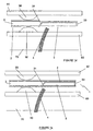
- a first embodiment of the delivery apparatus for delivering a fistula device 4 to a target vessel is indicated generally by reference number 1.
- the delivery apparatus 1 comprises an elongate cover member (an outer tube) 2 and an elongate support member (an inner tube) 3, as well as a fistula device 4 and a retaining sheath 5.
- the fistula device 4 is covered by the retaining sheath 5 which maintains the fistula device in a collapsed condition. In use, when the sheath 5 is removed, the fistula device 4 assumes an expanded condition.
- the sheath 5 has a penetrating tip 6 at the proximal end thereof.
- Penetrating tip 6 can alternatively be provided on the fistula device 4.
- the elongate support member 3 is of a generally elongate profile with a chambered edge 31 provided at a point on one elongate side thereof and a generally "L"-shaped member 32 provided towards the distal end of the elongate support member 3.
- the short limb 33 of the generally "L"-shaped member 32 provides a cover for the distal end of the sheath 5 and fistula device 4 and the chamfered edge 31 provides a protective cover for the perforating tip 6 at the proximal end of the sheath 5.
- the lesion or obstruction is indicated generally by reference numeral 50 and the coronary artery walls are indicated generally by reference numeral 60 and the myocardium by reference number 70.
- the delivery apparatus 1 is located in the coronary artery in the position as shown in Figure 1(a) .
- the elongate cover member is generally in the form of a restraining sheath and this elongate cover member 2 is positioned over the entire length of the elongate support member 3.
- the sheath-covered fistula device 4 is enveloped between the elongate support member 3 and the elongate cover member 2.
- the elongate cover member 2 is then withdrawn in a proximal direction along the coronary vessel so that the generally L-shaped member 32 of the elongate support member 3 is exposed.
- the sheath 5 is still covering the fistula device 4 thereby maintaining the fistula device 4 in the collapsed condition. Since the sheath 5 with fistula device 4 is not now covered by the elongate cover member 2, the sheath-covered fistula device 4 is released from the delivery apparatus 1 and springs outwardly from the elongate support member 3 in an arcuate manner, urging the tip of the fistula device 4 into the wall 60 of the coronary artery.
- the entire delivery apparatus 1 is then pulled proximally by the surgeon, so that the short limb 33 of the L-shaped member 32 urges the sheath-covered fistula device 4 through the coronary artery wall and the myocardium 70 and into the underlying heart chamber as shown in Figure 1(c) .
- the penetration of the fistula device 4 through the coronary artery wall 60 and myocardium 70 is facilitated by the penetrating tip 6 of the sheath 5 being firstly urged through the coronary artery wall 60 and myocardium 70 thereby creating a channel through which the rest of the fistula device 4 can pass easily.
- the fistula device 4 is still encased in the retaining delivery sheath 5 so that the fistula device 4 is maintained in the collapsed condition.
- the tip of the fistula device 4 is anchored in the myocardium by anchoring means so as to prevent it from being pulled out of the myocardium while the sheath 5 is being removed.
- anchoring means is described hereinbelow with reference to Figures 4 and 5 .
- the outer tube is advanced forward to its initial position in which it covers the retaining sheath 5 and the distal end of the elongate support member 3. Finally, the delivery apparatus 1 is then withdrawn from the coronary artery.
- the delivery apparatus may include a small reservoir for the collection and storage of oxygenated blood during systole (i.e. the period of contraction of the heart during each cardiac cycle) from the underlying chamber and the delivery of this blood to the coronary artery during diastole (i.e. the period of relaxation of the heart during each cardiac cycle).
- systole i.e. the period of contraction of the heart during each cardiac cycle
- diastole i.e. the period of relaxation of the heart during each cardiac cycle.
- the sheath 5 covers the fistula device 4 and maintains it in a collapsed configuration as described above.
- the penetrating tip 6 provided at the distal end of the sheath 5 is preferably made from a grade of ferritic steel having magnetic properties.
- An inner rod 37 is contained within the collapsed fistula 4 for part of the proximal portion thereof.
- the fistula device 4 is crimped onto the inner rod 37 at this proximal region. This prevents the fistula device 4 from moving when the sheath 5 is withdrawn.
- the sheath 5 must now be withdrawn from over the fistula device 4 by pulling it into the chamber of the heart and this necessities the use of a second device which is loaded inside of the heart chamber.
- This positioning of the second device within the heart chamber is preferably carried out percutaneously using an extractor catheter 40 which may be passed through the brachial artery in the arm.
- a wire loop 39 is used to firmly attach to the penetrating tip 6 of the sheath 5 and the magnetic attraction between the tip penetrating and the loop 39 can be used to locate and connect the extractor catheter 40 and the penetrating tip 6 of the sheath 5.
- the fistula device springs open, and the deployed portion of the fistula device then acts as the anchor to prevent the fistula device from being pulled through the myocardium as the sheath is removed.
- the fistula device opens, it lifts away from the inner rod 37 thus removing the physical connection between the fistula device 4 and delivery apparatus 1.
- the loop 39 is used to pull the sheath 5 off the fistula device 4 and pull it inside the extractor catheter 40 allowing it to be easily withdrawn from the patient's body through the chambers of the heart, aorta and finally brachial artery.
- the elongate cover member 2 is pushed back over the distal portion of the delivery apparatus 1, thereby shielding any jagged edges as the delivery apparatus 1 is being withdrawn through the coronary artery.
- the fistula device 4' includes a shoulder portion 38 which further assists in anchoring the fistula device 4' in the myocardium when the sheath 5' is being removed.
- the delivery apparatus in this embodiment is indicated generally by reference numeral 400. Like items are indicated with like numerals.
- the delivery apparatus 400 is shown during initial delivery.
- the apparatus 400 is enveloped within a restraining sheath 402.
- the apparatus 400 includes a penetrating (cannulating) tip 406 provided on the fistula device 404 and a retaining delivery sheath 405 on the fistula device 404.
- the apparatus 400 also includes a guide wire 450, a push rod 414 for the ventricular fistula device 404, and a delivery sheath pull wire 415 for the retaining delivery sheath 405.
- the cover member restraining sheath 402 is provided with a window 412.
- the ventricular fistula device 404 in the retaining delivery sheath 405 is deployed to penetrate the myocardium by advancing the restraining sheath 412 distally so that the window 412 aligns with the ventricular fistula device 405.
- the cannulating tip 406 is urged through the vessel and heart wall.
- the delivery sheath pull-wire 415 in the direction of the arrow A as indicated in Figure 5 the delivery sheath 405 is moved proximally off the ventricular fistula device, the latter being held in position by the ventricular fistula device pushrod 414.
- the delivery sheath 405 and cannulating tip 406 are recaptured by pulling the restraining sheath 412 proximally once more.
- the Ventricular fistula device pushrod 414 is shown embedded into the catheter shaft.
- the catheter shaft is bilumenal construction. Either the pushrod 414 or the pull-wire 415 or both are manufactured of a highly elastic material such as Nitinol.
- a balloon expandable ventricular fistula device may be employed.
- One lumen of the bilumenal shaft carries the inflation media/fluid.
- the distal cannulating tip can be retracted through it.
- the restraining sleeve has a window to release the Ventricular fistula device/sheath, and is moved distally for release and moved proximally for recapture.
- the restraining sheath (412 in Figures 4 and 5 ), could be a short distal sheath anchored to a pulling wire for reduced device profile.
- Each of the following 3 alternative methods of deployment of the delivery apparatus are further possible alternative methods of deploying the Ventricular fistula device and address the issue of anchoring the tip of the fistula device in the myocardium so that the fistula device is not pulled out of the heart wall when the sheath is removed.
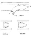
- FIG. 6a The normal velocity profile of the steady-state blood flow in the coronary artery is shown in Figure 6a . This velocity profile is changed by directing a 'jet' of high pressure blood down the centre of the artery. In largely concentric lesions, this serves to increase the total volumetric flow of blood to the distal portion of the artery, consequently supplying a greater amount of oxygen to the affected muscle region.
- a potential drawback of this design is the potential effect of the blood flow on the lesion.
- the altered sheer stress on the wall of the artery will undoubtedly lead to growth of the lesion over time.
- the rate at which the lesion grows, and the age of the patient may determine whether using the apparatus in this embodiment is an appropriate method of treatment.
- volumetric flow rate Q ⁇ VdA. Placing the fistula device proximal to the lesion attempts to change the distribution of V with respect to radial distance from centre of artery and thereby get a high flow rate down the artery.
- the delivery apparatus 1 may be loaded from inside the Heart Chamber out to the Coronary Artery.
- the embodiment of the apparatus is an attempt to avoid the issue of crossing the lesion 50.
- a guidewire 80 is advanced past the lesion 50 and magnetic means are employed to communicate between the tip of this guidewire 80 and the tip 6" of the fistula device 4" inside the heart chamber.
- the magnetic attraction between the tip of the guidewire 80 and the tip 6" helps guide the fistula device 4" through the heart wall and safely into the coronary artery distal of the lesion 50.
- the delivery apparatus may include a tunnel device 90 to aid the flow of blood across the lesion 50 in order to open it slightly.
- the device is essentially functioning as a solid stent.
- the tunnel device 90 may also be used to aid the passage of the delivery apparatus 1 across the lesion 50.
Landscapes
- Health & Medical Sciences (AREA)
- Engineering & Computer Science (AREA)
- Cardiology (AREA)
- Biomedical Technology (AREA)
- Life Sciences & Earth Sciences (AREA)
- Transplantation (AREA)
- Heart & Thoracic Surgery (AREA)
- Vascular Medicine (AREA)
- Oral & Maxillofacial Surgery (AREA)
- Animal Behavior & Ethology (AREA)
- General Health & Medical Sciences (AREA)
- Public Health (AREA)
- Veterinary Medicine (AREA)
- Surgical Instruments (AREA)
- Medical Preparation Storing Or Oral Administration Devices (AREA)
- Infusion, Injection, And Reservoir Apparatuses (AREA)
- Media Introduction/Drainage Providing Device (AREA)
Claims (20)
- Abgabevorrichtung zum Einbringen einer Fisteleinrichtung, wobei die Vorrichtung ein längliches Abdeckelement (2) mit einem proximalen Ende und einem distalen Ende umfasst; ein in dem länglichen Abdeckelement (2) angebrachtes längliches Stützelement (3), wobei das längliche Abdeckelement (2) und das längliche Stützelement (3) in Bezug zueinander bewegbar sind; und wobei die Vorrichtung weiter eine von dem Stützelement (3) getragene Fisteleinrichtung (4) umfasst,
dadurch gekennzeichnet, dass die Abgabevorrichtung zur Zufuhr der Fisteleinrichtung (4) in eine Herzwand eines Patienten dient, um die Fisteleinrichtung (4) in Kommunikation mit einer Herzkammer zu plazieren, wobei die Abgabevorrichtung Mittel (32) beinhaltet, um die Fisteleinrichtung (4) durch die Herzwand zu treiben; wobei die Vorrichtung weiter eine abnehmbare Rückhalteumhüllung (5) umfasst, die über mindestens einem Teil der Fisteleinrichtung (4) liegt, wobei die Fisteleinrichtung von einem zusammengefalteten Zustand in einen expandierten Zustand übergeht, wenn die Rückhalteumhüllung (5) entfernt wird; wobei die Fisteleinrichtung und/oder die Rückhalteumhüllung eine Durchstoßspitze (6) zum Durchstoßen der Herzwand beinhaltet, um die Passage der Fisteleinrichtung (4) durch diese zu erleichtern; und wobei das längliche Stützelement (3) ein erstes längliches Element und ein zweites Element (33), das wesentlich kürzer als das erste längliche Element (33) ist, umfasst, wobei das erste und zweite Element ein L-förmiges Element (32) bilden; und wobei im Gebrauch das längliche Abdeckelement (2) in einer proximalen Richtung bewegt wird, um zuzulassen, dass die Fisteleinrichtung (4) aus der Abgabevorrichtung freigegeben wird, und um die Fisteleinrichtung (4) zu einer gewünschten Stelle in der Herzwand zuzuführen. - Abgabevorrichtung, wie in Anspruch 1 beansprucht, wobei das Mittel (32) zum Treiben der Fisteleinrichtung durch die Herzwand den kurzen Arm (33) des L-förmigen Elements (32) umfasst und wobei das L-förmige Element (32) die Fisteleinrichtung (4) durch die Wand treibt, wenn das Stützelement (3) in eine proximale Richtung gezogen wird.
- Abgabevorrichtung, wie in einem der Ansprüche 1 oder 2 beansprucht, wobei das generell L-förmige Element (32) am distalen Ende des länglichen Stützelements angebracht ist.
- Abgabevorrichtung, wie in einem der vorgenannten Ansprüche beansprucht, wobei das zweite längliche Element (33) des generell L-förmigen Elements (32) am distalen Ende der Fisteleinrichtung an der Fisteleinrichtung (4) anliegt.
- Abgabevorrichtung, wie in einem der vorgenannten Ansprüche beansprucht, wobei das längliche Stützelement (3) über seine Länge im Wesentlichen gerade ist.
- Vorrichtung nach einem der vorgenannten Ansprüche, weiter einen an das zweite Element (33) gekoppelten Stab umfassend, und wobei der innere Stab sich mindestens teilweise in die Fisteleinrichtung (4) erstreckt.
- Vorrichtung nach einem der vorgenannten Ansprüche, wobei das Abdeckelement (2) röhrenförmig ist.
- Vorrichtung nach Anspruch 7, wobei das Stützelement (3) röhrenförmig ist.
- Vorrichtung nach einem der vorgenannten Ansprüche, wobei das Stützelement (3) eine abgefaste Kante (31) beinhaltet, um die Durchstoßspitze (6) zu schützen.
- Vorrichtung nach einem der vorgenannten Ansprüche, wobei die Fisteleinrichtung (4) Verankerungsmittel umfasst, um ein Verschieben der Fisteleinrichtung (4) beim Entfernen der Rückhalteumhüllung zu verhindern.
- Vorrichtung nach einem der vorgenannten Ansprüche, wobei die Fisteleinrichtung (4) selbstexpandierend ist.
- Vorrichtung nach einem der Ansprüche 1 bis 10, wobei die Fisteleinrichtung (4) ballonexpandierbar ist.
- Vorrichtung nach einem der Ansprüche 1 bis 10, wobei die Fisteleinrichtung (4) wärmeexpandiert wird.
- Vorrichtung nach einem der vorgenannten Ansprüche, weiter einen mit der Rückhalteumhüllung gekoppelten Zugdraht zum Entfernen der Rückhalteumhüllung in einer proximalen Richtung umfassend.
- Vorrichtung nach Anspruch 14, weiter eine mit der Rückhalteumhüllung gekoppelte Reißleine (39) zum Aufreißen der Rückhalteumhüllung zwecks Freigabe der Fisteleinrichtung (4) umfassend.
- Vorrichtung nach Anspruch 15, weiter einen mit der Fisteleinrichtung (4) gekoppelten Schiebestab zum in Position Halten der Fisteleinrichtung beim Entfernen der Rückhalteumhüllung (5) umfassend.
- Vorrichtung nach Anspruch 14, wobei die Rückhalteumhüllung (5) biologisch resorbierbar ist.
- Abgabevorrichtung, wie in einem der vorgenannten Ansprüche beansprucht, wobei die Fisteleinrichtung (4) einen Stent (4) umfasst, der zwischen einem zusammengefalteten Zustand, wenn er von der Rückhalteumhüllung (5) bedeckt ist, und einem expandierten Zustand, wenn die Umhüllung (5) entfernt ist, bewegbar ist.
- Abgabevorrichtung, wie in einem der vorgenannten Ansprüche beansprucht, wobei das längliche Abdeckelement eine äußere Röhre umfasst, die das längliche Stützelement abdeckt, und letzteres in Form einer inneren Röhre vorliegt.
- Abgabevorrichtung, wie in einem der vorgenannten Ansprüche beansprucht, wobei die Fisteleinrichtung (4) bewegbar ist zwischen einer Lagerform, worin die Fisteleinrichtung (4) in der Abgabevorrichtung enthalten ist, wobei die Fisteleinrichtung entlang dem länglichen Abdeckelement (3) an einer länglichen Seite der Fisteleinrichtung liegt und wobei das längliche Stützelement an der anderen länglichen Seite der Fisteleinrichtung liegt; und einer Abgabeform, wobei das längliche Abdeckelement (3) in einer proximalen Richtung bewegt wird, um die Verbindungsleitung aus der Abgabevorrichtung freizugeben.
Applications Claiming Priority (2)
| Application Number | Priority Date | Filing Date | Title |
|---|---|---|---|
| IE20030531A IES20030531A2 (en) | 2003-07-17 | 2003-07-17 | Methods and devices for placing a fistula device in fluid communication with a target vessel |
| IE20030531 | 2003-07-17 |
Publications (2)
| Publication Number | Publication Date |
|---|---|
| EP1498086A1 EP1498086A1 (de) | 2005-01-19 |
| EP1498086B1 true EP1498086B1 (de) | 2008-11-05 |
Family
ID=33463006
Family Applications (1)
| Application Number | Title | Priority Date | Filing Date |
|---|---|---|---|
| EP04394044A Expired - Lifetime EP1498086B1 (de) | 2003-07-17 | 2004-07-16 | Vorrichtung zum Plazieren eines Kanals in Flüssigkeitsverbindung mit einem Zielgefäss |
Country Status (4)
| Country | Link |
|---|---|
| US (1) | US7727268B2 (de) |
| EP (1) | EP1498086B1 (de) |
| DE (1) | DE602004017545D1 (de) |
| IE (1) | IES20030531A2 (de) |
Cited By (15)
| Publication number | Priority date | Publication date | Assignee | Title |
|---|---|---|---|---|
| US10856984B2 (en) | 2017-08-25 | 2020-12-08 | Neovasc Tiara Inc. | Sequentially deployed transcatheter mitral valve prosthesis |
| US10940001B2 (en) | 2012-05-30 | 2021-03-09 | Neovasc Tiara Inc. | Methods and apparatus for loading a prosthesis onto a delivery system |
| US11311376B2 (en) | 2019-06-20 | 2022-04-26 | Neovase Tiara Inc. | Low profile prosthetic mitral valve |
| US11357622B2 (en) | 2016-01-29 | 2022-06-14 | Neovase Tiara Inc. | Prosthetic valve for avoiding obstruction of outflow |
| US11389291B2 (en) | 2013-04-04 | 2022-07-19 | Neovase Tiara Inc. | Methods and apparatus for delivering a prosthetic valve to a beating heart |
| US11413139B2 (en) | 2011-11-23 | 2022-08-16 | Neovasc Tiara Inc. | Sequentially deployed transcatheter mitral valve prosthesis |
| US11419720B2 (en) | 2010-05-05 | 2022-08-23 | Neovasc Tiara Inc. | Transcatheter mitral valve prosthesis |
| US11464631B2 (en) | 2016-11-21 | 2022-10-11 | Neovasc Tiara Inc. | Methods and systems for rapid retraction of a transcatheter heart valve delivery system |
| US11491006B2 (en) | 2019-04-10 | 2022-11-08 | Neovasc Tiara Inc. | Prosthetic valve with natural blood flow |
| US11497602B2 (en) | 2012-02-14 | 2022-11-15 | Neovasc Tiara Inc. | Methods and apparatus for engaging a valve prosthesis with tissue |
| US11602429B2 (en) | 2019-04-01 | 2023-03-14 | Neovasc Tiara Inc. | Controllably deployable prosthetic valve |
| US11737872B2 (en) | 2018-11-08 | 2023-08-29 | Neovasc Tiara Inc. | Ventricular deployment of a transcatheter mitral valve prosthesis |
| US11779742B2 (en) | 2019-05-20 | 2023-10-10 | Neovasc Tiara Inc. | Introducer with hemostasis mechanism |
| US11998447B2 (en) | 2019-03-08 | 2024-06-04 | Neovasc Tiara Inc. | Retrievable prosthesis delivery system |
| US12109111B2 (en) | 2015-12-15 | 2024-10-08 | Neovasc Tiara Inc. | Transseptal delivery system |
Families Citing this family (29)
| Publication number | Priority date | Publication date | Assignee | Title |
|---|---|---|---|---|
| US20070010781A1 (en) * | 2005-06-27 | 2007-01-11 | Venkataramana Vijay | Implantable aorto-coronary sinus shunt for myocardial revascularization |
| US20070010780A1 (en) * | 2005-06-27 | 2007-01-11 | Venkataramana Vijay | Methods of implanting an aorto-coronary sinus shunt for myocardial revascularization |
| US20080294235A1 (en) * | 2007-05-24 | 2008-11-27 | Inverthis Ltd. | Bypass graft device and delivery system and method |
| US20090112238A1 (en) * | 2007-10-26 | 2009-04-30 | Vance Products Inc., D/B/A Cook Urological Inc. | Fistula brush device |
| US20100082056A1 (en) * | 2008-04-04 | 2010-04-01 | Akshay Mavani | Implantable fistula closure device |
| WO2010028300A1 (en) * | 2008-09-04 | 2010-03-11 | Curaseal Inc. | Inflatable device for enteric fistula treatment |
| US11986150B2 (en) | 2009-12-15 | 2024-05-21 | Lumendi Ltd. | Method and apparatus for manipulating the side wall of a body lumen or body cavity so as to provide increased visualization of the same and/or increased access to the same, and/or for stabilizing instruments relative to the same |
| US10149601B2 (en) | 2009-12-15 | 2018-12-11 | Lumendi Ltd. | Method and apparatus for manipulating the side wall of a body lumen or body cavity so as to provide increased visualization of the same and/or increased access to the same, and/or for stabilizing instruments relative to the same |
| US10485401B2 (en) | 2009-12-15 | 2019-11-26 | Lumendi Ltd. | Method and apparatus for manipulating the side wall of a body lumen or body cavity so as to provide increased visualization of the same and/or increased access to the same, and/or for stabilizing instruments relative to the same |
| US9986893B2 (en) | 2009-12-15 | 2018-06-05 | Cornell University | Method and apparatus for manipulating the side wall of a body lumen or body cavity so as to provide increased visualization of the same and/or increased access to the same, and/or for stabilizing instruments relative to the same |
| US8979884B2 (en) | 2009-12-15 | 2015-03-17 | Cornell University | Method and apparatus for stabilizing, straightening, expanding and/or flattening the side wall of a body lumen and/or body cavity so as to provide increased visualization of the same and/or increased access to the same, and/or for stabilizing instruments relative to the same |
| US11877722B2 (en) | 2009-12-15 | 2024-01-23 | Cornell University | Method and apparatus for manipulating the side wall of a body lumen or body cavity |
| US12121209B2 (en) | 2014-02-11 | 2024-10-22 | Cornell University | Method and apparatus for providing increased visualization and manipulation of a body side wall |
| CA2817552C (en) | 2010-11-16 | 2020-03-24 | Tva Medical, Inc. | Devices and methods for forming a fistula |
| JP6122424B2 (ja) | 2011-06-16 | 2017-04-26 | キュラシール インコーポレイテッド | 瘻孔処置用デバイス及びその関連方法 |
| JP6127042B2 (ja) | 2011-06-17 | 2017-05-10 | キュラシール インコーポレイテッド | 瘻孔処置用デバイスと方法 |
| WO2014059351A1 (en) | 2012-10-11 | 2014-04-17 | Tva Medical, Inc. | Devices and methods for fistula formation |
| CA2905591C (en) | 2013-03-14 | 2023-02-28 | Tva Medical, Inc. | Fistula formulation devices and methods therefor |
| US10695534B2 (en) | 2014-03-14 | 2020-06-30 | Tva Medical, Inc. | Fistula formation devices and methods therefor |
| US10646666B2 (en) | 2014-08-27 | 2020-05-12 | Tva Medical, Inc. | Cryolipolysis devices and methods therefor |
| US10603040B1 (en) | 2015-02-09 | 2020-03-31 | Tva Medical, Inc. | Methods for treating hypertension and reducing blood pressure with formation of fistula |
| WO2016193820A1 (en) * | 2015-06-03 | 2016-12-08 | Lumendi Ltd. | Method and apparatus for manipulating the side wall of a body lumen or body cavity so as to provide increased visualization of th same and/or increased access to the same, and/or for stabilizing instruments relative to the same |
| CN108883251B (zh) | 2016-01-15 | 2021-12-07 | Tva医疗公司 | 用于推进金属丝的装置和方法 |
| US10874422B2 (en) | 2016-01-15 | 2020-12-29 | Tva Medical, Inc. | Systems and methods for increasing blood flow |
| AU2017208069B2 (en) | 2016-01-15 | 2021-11-25 | Tva Medical, Inc. | Devices and methods for forming a fistula |
| JP7219090B2 (ja) | 2016-01-15 | 2023-02-07 | ティーブイエー メディカル, インコーポレイテッド | 脈管を接着するためのシステムおよび方法 |
| CN109982652B (zh) | 2016-09-25 | 2022-08-05 | Tva医疗公司 | 血管支架装置和方法 |
| WO2020132505A2 (en) | 2018-12-20 | 2020-06-25 | Gage Shawn | Apparatus and method for implanting an arteriovenous graft |
| EP4243910A4 (de) | 2020-11-16 | 2024-12-25 | Lumendi Ltd. | Verfahren und vorrichtung zum wenden einer hohlen hülse und darauf folgender umkehr einer umgekehrten hohlen hülse |
Family Cites Families (52)
| Publication number | Priority date | Publication date | Assignee | Title |
|---|---|---|---|---|
| US5287861A (en) * | 1992-10-30 | 1994-02-22 | Wilk Peter J | Coronary artery by-pass method and associated catheter |
| US5409019A (en) * | 1992-10-30 | 1995-04-25 | Wilk; Peter J. | Coronary artery by-pass method |
| FR2726402B1 (fr) * | 1994-10-27 | 1996-12-06 | Cinch Connecteurs Sa | Perfectionnements aux connecteurs electriques |
| ATE515237T1 (de) * | 1995-10-13 | 2011-07-15 | Medtronic Vascular Inc | Vorrichtung und system bei einem interstitiellen transvaskulären eingriff |
| US6375615B1 (en) * | 1995-10-13 | 2002-04-23 | Transvascular, Inc. | Tissue penetrating catheters having integral imaging transducers and their methods of use |
| US6302875B1 (en) * | 1996-10-11 | 2001-10-16 | Transvascular, Inc. | Catheters and related devices for forming passageways between blood vessels or other anatomical structures |
| US5830224A (en) * | 1996-03-15 | 1998-11-03 | Beth Israel Deaconess Medical Center | Catheter apparatus and methodology for generating a fistula on-demand between closely associated blood vessels at a pre-chosen anatomic site in-vivo |
| US5755682A (en) * | 1996-08-13 | 1998-05-26 | Heartstent Corporation | Method and apparatus for performing coronary artery bypass surgery |
| WO1998008456A1 (en) | 1996-08-26 | 1998-03-05 | Transvascular, Inc. | Methods and apparatus for transmyocardial direct coronary revascularization |
| US5655548A (en) * | 1996-09-16 | 1997-08-12 | Circulation, Inc. | Method for treatment of ischemic heart disease by providing transvenous myocardial perfusion |
| US6026814A (en) * | 1997-03-06 | 2000-02-22 | Scimed Life Systems, Inc. | System and method for percutaneous coronary artery bypass |
| US6035856A (en) * | 1997-03-06 | 2000-03-14 | Scimed Life Systems | Percutaneous bypass with branching vessel |
| WO1998049964A1 (en) | 1997-05-08 | 1998-11-12 | C. R. Bard, Inc. | Tmr stent and delivery system |
| US6092526A (en) * | 1997-06-19 | 2000-07-25 | Scimed Life Systems, Inc. | Percutaneous chamber-to-artery bypass |
| US5908029A (en) * | 1997-08-15 | 1999-06-01 | Heartstent Corporation | Coronary artery bypass with reverse flow |
| US6102941A (en) * | 1997-10-06 | 2000-08-15 | Heartstent Corporation | Transmyocardial implant with coronary ingrowth |
| US5984956A (en) * | 1997-10-06 | 1999-11-16 | Heartstent Corporation | Transmyocardial implant |
| US6214041B1 (en) * | 1998-01-20 | 2001-04-10 | Heartstent Corporation | Transmyocardial implant with septal perfusion |
| US6651670B2 (en) | 1998-02-13 | 2003-11-25 | Ventrica, Inc. | Delivering a conduit into a heart wall to place a coronary vessel in communication with a heart chamber and removing tissue from the vessel or heart wall to facilitate such communication |
| CA2320956A1 (en) | 1998-02-13 | 1999-08-19 | Ventrica, Inc. | Methods and devices providing transmyocardial blood flow to the arterial vascular system of the heart |
| US20010041902A1 (en) | 1998-02-13 | 2001-11-15 | Michael J. Lynch | Anastomotic methods and devices for placing a target vessel in fluid communication with a source of blood |
| US6808498B2 (en) | 1998-02-13 | 2004-10-26 | Ventrica, Inc. | Placing a guide member into a heart chamber through a coronary vessel and delivering devices for placing the coronary vessel in communication with the heart chamber |
| US6076529A (en) * | 1998-04-20 | 2000-06-20 | Heartstent Corporation | Transmyocardial implant with inserted vessel |
| US6029672A (en) * | 1998-04-20 | 2000-02-29 | Heartstent Corporation | Transmyocardial implant procedure and tools |
| US6113823A (en) * | 1998-06-09 | 2000-09-05 | Heartstent Corporation | Pyrolytic carbon transmyocardial implant |
| US6063915A (en) | 1998-07-30 | 2000-05-16 | Hercules Incorporated | Carrageenan compositions and methods for their production |
| CN1209376C (zh) | 1998-07-31 | 2005-07-06 | 马铃薯及衍生产品合作销售生产阿韦贝公司 | 淀粉的氧化 |
| US6053942A (en) * | 1998-08-18 | 2000-04-25 | Heartstent Corporation | Transmyocardial implant with coronary stent |
| US6254564B1 (en) | 1998-09-10 | 2001-07-03 | Percardia, Inc. | Left ventricular conduit with blood vessel graft |
| JP2002524196A (ja) | 1998-09-10 | 2002-08-06 | パーカーディア,インコーポレイティド | 左心室血管再生用の経心筋シャントおよびその取付機構 |
| US6196230B1 (en) * | 1998-09-10 | 2001-03-06 | Percardia, Inc. | Stent delivery system and method of use |
| US6641610B2 (en) | 1998-09-10 | 2003-11-04 | Percardia, Inc. | Valve designs for left ventricular conduits |
| US6093194A (en) * | 1998-09-14 | 2000-07-25 | Endocare, Inc. | Insertion device for stents and methods for use |
| US6162231A (en) | 1998-09-14 | 2000-12-19 | Endocare, Inc. | Stent insertion device |
| US6197050B1 (en) * | 1998-09-14 | 2001-03-06 | Heartstent Corporation | Transmyocardial implant with compliance collar |
| JP2002527141A (ja) | 1998-10-13 | 2002-08-27 | ベントリカ, インコーポレイテッド | 心筋を横切る冠状動脈バイパスの実施における使用のためのデバイスおよび方法 |
| EP1150611A1 (de) | 1999-01-15 | 2001-11-07 | Ventrica, Inc. | Methode und gerät zum überbrücken eines verstopfteb zielgefässes durch die verbindung des gefässes mit einer blut enthaltenden herzkammer |
| US6193726B1 (en) * | 1999-01-15 | 2001-02-27 | Heartstent Corporation | Insertion tool for transmyocardial implant |
| CA2360587A1 (en) | 1999-01-15 | 2000-07-20 | Darin C. Gittings | Methods and devices for forming vascular anastomoses |
| US7025773B2 (en) * | 1999-01-15 | 2006-04-11 | Medtronic, Inc. | Methods and devices for placing a conduit in fluid communication with a target vessel |
| US6231597B1 (en) * | 1999-02-16 | 2001-05-15 | Mark E. Deem | Apparatus and methods for selectively stenting a portion of a vessel wall |
| WO2000066009A1 (en) | 1999-05-03 | 2000-11-09 | Ventrica, Inc. | Methods and devices for forming a conduit between a target vessel and a blood source |
| EP1180976A1 (de) | 1999-05-03 | 2002-02-27 | Ventrica Inc. | Verfahren und vorrichtung zum platzieren eines kanals in flüssigkeitsverbindung mit einem zielgefäss |
| US6182668B1 (en) * | 1999-05-13 | 2001-02-06 | Heartstent Corporation | Transmyocardial implant with induced tissue flap |
| US6302892B1 (en) | 1999-08-04 | 2001-10-16 | Percardia, Inc. | Blood flow conduit delivery system and method of use |
| JP2003510143A (ja) | 1999-08-04 | 2003-03-18 | パーカーディア インコーポレイテッド | 直接的冠状血管再生方法及び装置 |
| US6253768B1 (en) | 1999-08-04 | 2001-07-03 | Percardia, Inc. | Vascular graft bypass |
| US6638237B1 (en) | 1999-08-04 | 2003-10-28 | Percardia, Inc. | Left ventricular conduits and methods for delivery |
| US6113630A (en) * | 1999-08-13 | 2000-09-05 | Heartstent Corporation | Transmyocardial implant with minimized coronary insertion |
| US6605053B1 (en) | 1999-09-10 | 2003-08-12 | Percardia, Inc. | Conduit designs and related methods for optimal flow control |
| US20030109886A1 (en) * | 2001-06-27 | 2003-06-12 | Martin Keegan | Catheter |
| US7789860B2 (en) * | 2001-06-27 | 2010-09-07 | Salviac Limited | Catheter for delivery and/or retrieval of a medical device |
-
2003
- 2003-07-17 IE IE20030531A patent/IES20030531A2/xx not_active IP Right Cessation
-
2004
- 2004-07-07 US US10/887,541 patent/US7727268B2/en active Active
- 2004-07-16 EP EP04394044A patent/EP1498086B1/de not_active Expired - Lifetime
- 2004-07-16 DE DE602004017545T patent/DE602004017545D1/de not_active Expired - Lifetime
Cited By (25)
| Publication number | Priority date | Publication date | Assignee | Title |
|---|---|---|---|---|
| US12611303B2 (en) | 2010-05-05 | 2026-04-28 | Neovasc Tiara Inc. | Transcatheter mitral valve prosthesis |
| US11419720B2 (en) | 2010-05-05 | 2022-08-23 | Neovasc Tiara Inc. | Transcatheter mitral valve prosthesis |
| US11413139B2 (en) | 2011-11-23 | 2022-08-16 | Neovasc Tiara Inc. | Sequentially deployed transcatheter mitral valve prosthesis |
| US12053369B2 (en) | 2011-11-23 | 2024-08-06 | Neovasc Tiara Inc. | Sequentially deployed transcatheter mitral valve prosthesis |
| US12138159B2 (en) | 2012-02-14 | 2024-11-12 | Neovasc Tiara Inc. | Methods and apparatus for engaging a valve prosthesis with tissue |
| US11497602B2 (en) | 2012-02-14 | 2022-11-15 | Neovasc Tiara Inc. | Methods and apparatus for engaging a valve prosthesis with tissue |
| US11617650B2 (en) | 2012-05-30 | 2023-04-04 | Neovasc Tiara Inc. | Methods and apparatus for loading a prosthesis onto a delivery system |
| US11389294B2 (en) | 2012-05-30 | 2022-07-19 | Neovasc Tiara Inc. | Methods and apparatus for loading a prosthesis onto a delivery system |
| US10940001B2 (en) | 2012-05-30 | 2021-03-09 | Neovasc Tiara Inc. | Methods and apparatus for loading a prosthesis onto a delivery system |
| US11389291B2 (en) | 2013-04-04 | 2022-07-19 | Neovase Tiara Inc. | Methods and apparatus for delivering a prosthetic valve to a beating heart |
| US12109111B2 (en) | 2015-12-15 | 2024-10-08 | Neovasc Tiara Inc. | Transseptal delivery system |
| US12193932B2 (en) | 2016-01-29 | 2025-01-14 | Neovasc Tiara Inc. | Prosthetic valve for avoiding obstruction of outflow |
| US11357622B2 (en) | 2016-01-29 | 2022-06-14 | Neovase Tiara Inc. | Prosthetic valve for avoiding obstruction of outflow |
| US11464631B2 (en) | 2016-11-21 | 2022-10-11 | Neovasc Tiara Inc. | Methods and systems for rapid retraction of a transcatheter heart valve delivery system |
| US12201524B2 (en) | 2016-11-21 | 2025-01-21 | Neovasc Tiara Inc. | Methods and systems for rapid retraction of a transcatheter heart valve delivery system |
| US11793640B2 (en) | 2017-08-25 | 2023-10-24 | Neovasc Tiara Inc. | Sequentially deployed transcatheter mitral valve prosthesis |
| US10856984B2 (en) | 2017-08-25 | 2020-12-08 | Neovasc Tiara Inc. | Sequentially deployed transcatheter mitral valve prosthesis |
| US11737872B2 (en) | 2018-11-08 | 2023-08-29 | Neovasc Tiara Inc. | Ventricular deployment of a transcatheter mitral valve prosthesis |
| US11998447B2 (en) | 2019-03-08 | 2024-06-04 | Neovasc Tiara Inc. | Retrievable prosthesis delivery system |
| US11602429B2 (en) | 2019-04-01 | 2023-03-14 | Neovasc Tiara Inc. | Controllably deployable prosthetic valve |
| US12036117B2 (en) | 2019-04-10 | 2024-07-16 | Neovasc Tiara Inc. | Prosthetic valve with natural blood flow |
| US11491006B2 (en) | 2019-04-10 | 2022-11-08 | Neovasc Tiara Inc. | Prosthetic valve with natural blood flow |
| US11779742B2 (en) | 2019-05-20 | 2023-10-10 | Neovasc Tiara Inc. | Introducer with hemostasis mechanism |
| US11931254B2 (en) | 2019-06-20 | 2024-03-19 | Neovasc Tiara Inc. | Low profile prosthetic mitral valve |
| US11311376B2 (en) | 2019-06-20 | 2022-04-26 | Neovase Tiara Inc. | Low profile prosthetic mitral valve |
Also Published As
| Publication number | Publication date |
|---|---|
| US7727268B2 (en) | 2010-06-01 |
| EP1498086A1 (de) | 2005-01-19 |
| US20050033401A1 (en) | 2005-02-10 |
| IES20030531A2 (en) | 2005-09-21 |
| DE602004017545D1 (de) | 2008-12-18 |
Similar Documents
| Publication | Publication Date | Title |
|---|---|---|
| EP1498086B1 (de) | Vorrichtung zum Plazieren eines Kanals in Flüssigkeitsverbindung mit einem Zielgefäss | |
| US20250249164A1 (en) | Methods for routing a guidewire from a first vessel and through a second vessel in lower extremity vasculature | |
| JP5527850B2 (ja) | 組織貫通装置及びその方法 | |
| EP1765451B1 (de) | Vorrichtungen für die erzeugung einer arteriovenösen fistel | |
| JP6294950B2 (ja) | ステントレス支持構造 | |
| EP2012708B1 (de) | Gerät zur aufrechterhatlung des flüssigkeitsflusses durch körpergänge | |
| JP5458099B2 (ja) | 血管壁に接近させる弁を有する血管器具 | |
| JP4874502B2 (ja) | 内腔内プロテーゼを送達するための装置ならびにその作製および使用方法 | |
| US20060282161A1 (en) | Valve annulus reduction system | |
| EP3590477A1 (de) | Systeme zur bereitstellung oder aufrechterhaltung des flüssigkeitsflusses durch körpergänge | |
| EP1637083A2 (de) | Biegsames Transmyokardimplantat zur Induktion der Angiogenese | |
| WO2004098393A2 (en) | Delivery system for endoluminal implant | |
| JP2009527316A (ja) | 最小侵襲性血管内治療装置 | |
| JP2001503291A (ja) | 経静脈心筋灌流を提供することによって虚血性心臓疾患を処置するための装置 | |
| JP2001527440A (ja) | 心筋貫通性直接的冠血管再形成のための方法及び装置 | |
| EP1500382B1 (de) | Stents und Stenteinbringungssysteme | |
| CN111712217B (zh) | 用以置换二尖瓣的装置及其使用方法 | |
| CN116916832A (zh) | 柔性分流植入物 | |
| US20070010781A1 (en) | Implantable aorto-coronary sinus shunt for myocardial revascularization | |
| IES84653Y1 (en) | Methods and devices for placing a fistula device in fluid communication with a target vessel | |
| WO2026020001A1 (en) | Medical system | |
| US20070010780A1 (en) | Methods of implanting an aorto-coronary sinus shunt for myocardial revascularization | |
| WO2007002616A2 (en) | Implantable aorto-coronary sinus shunt for myocardial revascularization and method of usng the same | |
| WO2018208622A1 (en) | Devices and methods for treating an artery |
Legal Events
| Date | Code | Title | Description |
|---|---|---|---|
| PUAI | Public reference made under article 153(3) epc to a published international application that has entered the european phase |
Free format text: ORIGINAL CODE: 0009012 |
|
| AK | Designated contracting states |
Kind code of ref document: A1 Designated state(s): AT BE BG CH CY CZ DE DK EE ES FI FR GB GR HU IE IT LI LU MC NL PL PT RO SE SI SK TR |
|
| AX | Request for extension of the european patent |
Extension state: AL HR LT LV MK |
|
| 17P | Request for examination filed |
Effective date: 20050610 |
|
| AKX | Designation fees paid |
Designated state(s): DE FR GB IE IT |
|
| 17Q | First examination report despatched |
Effective date: 20061103 |
|
| RTI1 | Title (correction) |
Free format text: DEVICES FOR PLACING A FISTULA DEVICE IN FLUID COMMUNICATION WITH A TARGET VESSEL |
|
| GRAP | Despatch of communication of intention to grant a patent |
Free format text: ORIGINAL CODE: EPIDOSNIGR1 |
|
| RIN1 | Information on inventor provided before grant (corrected) |
Inventor name: THORNTON, RONAN Inventor name: FRANCIS, RICHARD Inventor name: CUNNIFFE, BRENDAN Inventor name: DUFFY, NIALL, C/O MEDTRONIC Inventor name: COYLE, NOEL |
|
| GRAS | Grant fee paid |
Free format text: ORIGINAL CODE: EPIDOSNIGR3 |
|
| GRAA | (expected) grant |
Free format text: ORIGINAL CODE: 0009210 |
|
| AK | Designated contracting states |
Kind code of ref document: B1 Designated state(s): DE FR GB IE IT |
|
| REG | Reference to a national code |
Ref country code: GB Ref legal event code: FG4D |
|
| REG | Reference to a national code |
Ref country code: IE Ref legal event code: FG4D |
|
| REF | Corresponds to: |
Ref document number: 602004017545 Country of ref document: DE Date of ref document: 20081218 Kind code of ref document: P |
|
| PLBE | No opposition filed within time limit |
Free format text: ORIGINAL CODE: 0009261 |
|
| STAA | Information on the status of an ep patent application or granted ep patent |
Free format text: STATUS: NO OPPOSITION FILED WITHIN TIME LIMIT |
|
| 26N | No opposition filed |
Effective date: 20090806 |
|
| GBPC | Gb: european patent ceased through non-payment of renewal fee |
Effective date: 20090716 |
|
| PG25 | Lapsed in a contracting state [announced via postgrant information from national office to epo] |
Ref country code: GB Free format text: LAPSE BECAUSE OF NON-PAYMENT OF DUE FEES Effective date: 20090716 |
|
| PG25 | Lapsed in a contracting state [announced via postgrant information from national office to epo] |
Ref country code: IT Free format text: LAPSE BECAUSE OF NON-PAYMENT OF DUE FEES Effective date: 20090716 |
|
| PGFP | Annual fee paid to national office [announced via postgrant information from national office to epo] |
Ref country code: DE Payment date: 20140729 Year of fee payment: 11 Ref country code: IE Payment date: 20140728 Year of fee payment: 11 |
|
| PGFP | Annual fee paid to national office [announced via postgrant information from national office to epo] |
Ref country code: FR Payment date: 20140717 Year of fee payment: 11 |
|
| REG | Reference to a national code |
Ref country code: DE Ref legal event code: R119 Ref document number: 602004017545 Country of ref document: DE |
|
| REG | Reference to a national code |
Ref country code: IE Ref legal event code: MM4A |
|
| PG25 | Lapsed in a contracting state [announced via postgrant information from national office to epo] |
Ref country code: DE Free format text: LAPSE BECAUSE OF NON-PAYMENT OF DUE FEES Effective date: 20160202 |
|
| REG | Reference to a national code |
Ref country code: FR Ref legal event code: ST Effective date: 20160331 |
|
| PG25 | Lapsed in a contracting state [announced via postgrant information from national office to epo] |
Ref country code: FR Free format text: LAPSE BECAUSE OF NON-PAYMENT OF DUE FEES Effective date: 20150731 |
|
| PG25 | Lapsed in a contracting state [announced via postgrant information from national office to epo] |
Ref country code: IE Free format text: LAPSE BECAUSE OF NON-PAYMENT OF DUE FEES Effective date: 20150716 |