EP1498188A2 - Anordnung zum axialen Antrieb eines Zufuhrschlauchs - Google Patents
Anordnung zum axialen Antrieb eines Zufuhrschlauchs Download PDFInfo
- Publication number
- EP1498188A2 EP1498188A2 EP04075739A EP04075739A EP1498188A2 EP 1498188 A2 EP1498188 A2 EP 1498188A2 EP 04075739 A EP04075739 A EP 04075739A EP 04075739 A EP04075739 A EP 04075739A EP 1498188 A2 EP1498188 A2 EP 1498188A2
- Authority
- EP
- European Patent Office
- Prior art keywords
- supply hose
- hose
- arrangement according
- driving
- driving wheels
- Prior art date
- Legal status (The legal status is an assumption and is not a legal conclusion. Google has not performed a legal analysis and makes no representation as to the accuracy of the status listed.)
- Granted
Links
Images


Classifications
-
- B—PERFORMING OPERATIONS; TRANSPORTING
- B65—CONVEYING; PACKING; STORING; HANDLING THIN OR FILAMENTARY MATERIAL
- B65H—HANDLING THIN OR FILAMENTARY MATERIAL, e.g. SHEETS, WEBS, CABLES
- B65H51/00—Forwarding filamentary material
- B65H51/02—Rotary devices, e.g. with helical forwarding surfaces
- B65H51/04—Rollers, pulleys, capstans, or intermeshing rotary elements
- B65H51/08—Rollers, pulleys, capstans, or intermeshing rotary elements arranged to operate in groups or in co-operation with other elements
- B65H51/10—Rollers, pulleys, capstans, or intermeshing rotary elements arranged to operate in groups or in co-operation with other elements with opposed coacting surfaces, e.g. providing nips
-
- B—PERFORMING OPERATIONS; TRANSPORTING
- B05—SPRAYING OR ATOMISING IN GENERAL; APPLYING FLUENT MATERIALS TO SURFACES, IN GENERAL
- B05B—SPRAYING APPARATUS; ATOMISING APPARATUS; NOZZLES
- B05B13/00—Machines or plants for applying liquids or other fluent materials to surfaces of objects or other work by spraying, not covered by groups B05B1/00 - B05B11/00
- B05B13/02—Means for supporting work; Arrangement or mounting of spray heads; Adaptation or arrangement of means for feeding work
- B05B13/04—Means for supporting work; Arrangement or mounting of spray heads; Adaptation or arrangement of means for feeding work the spray heads being moved during spraying operation
-
- B—PERFORMING OPERATIONS; TRANSPORTING
- B05—SPRAYING OR ATOMISING IN GENERAL; APPLYING FLUENT MATERIALS TO SURFACES, IN GENERAL
- B05B—SPRAYING APPARATUS; ATOMISING APPARATUS; NOZZLES
- B05B15/00—Details of spraying plant or spraying apparatus not otherwise provided for; Accessories
Definitions
- the present invention concerns an arrangement of the type described in the introduction to claim 1.
- the guide tube is provided with longitudinal slits, and is equipped with a cartridge that is arranged to be displaceable forwards and backwards along this.
- the cartridge is equipped with one or several spray nozzles.
- the cartridge is connected to a supply hose for pressure medium or spray medium, such as water, air, cleaning fluid, paint, sand, etc.
- the cartridge is displaced forwards and backwards in the guide tube with the aid of the supply hose, which is in turn driven with the aid of two pairs of friction wheels on each side of the supply hose.
- the arrangement of driving the supply hose with friction wheels as described above involves a number of disadvantages and problems.
- a drive device with two pairs of driving wheels is also revealed in GB 2037392.
- the driving wheels have the form of friction wheels that grip around the hose to feed the hose forwards.
- the driving arrangement is mounted in this case in an apparatus for flushing drains in which the hose is to be fed into the drain and subsequently withdrawn. Continuous driving inwards and outwards is not relevant in this case.
- US 4592282 shows feeding of hose-formed explosive into a drilled hole using a similar driving arrangement with pairs of wheels. Also in this case, a continuous driving arrangement for continuous forwards and backwards feed is not concerned.
- a hose-feed apparatus is also revealed in US 4240017 with pairs of driving wheels, one driving roller that grips against the hose and against a tension roller.
- a cleaning apparatus for drains in which a hose is fed out is revealed in the Japanese patent 2001-300458.
- Three obliquely placed rotation wheels are used to achieve rotation of the hose in this case.
- Each rotation wheel is placed at an oblique angle of 45° degrees to the direction of feed of the hose, and the rotation wheel exerts a contact force against the hose along a pressure line (an edge). This results in heavy wear on the hose.
- the principal aim of the present invention is to achieve an arrangement adapted for continuous forwards and backwards driving of a supply hose, which arrangement wholly or partially solves the disadvantages and problems described above.
- This is achieved according to the invention through an arrangement that displays the features specified in claim 1. Wear of the supply hose that arises when using previously known solutions can be significantly reduced in accordance with the invention.
- the arrangement for axial driving of a supply hose for pressure medium or spray medium in the form of fluid, gaseous or solid, granule-formed or powder-formed, material according to the invention is characterised in that the arrangement has three driving wheels with concave jacket surfaces, which jacket surfaces make contact in a congruent manner with the supply hose and surround the hose around at least 100° degrees of the circumference of the supply hose.
- the present invention has a greater total area of contact with the supply hose, divided into sections, which gives higher friction against the driving wheels. This means that the contact pressure between the driving wheels and the supply hose can be relatively low. This in turn means that wear of the supply hose is reduced.
- the driving wheels should be manufactured, at least in their concave jacket surfaces, from a polymer material with a coefficient of friction, ⁇ >0.8 and preferably ⁇ >0.9, between any driving wheel and the supply hose. Furthermore, the driving wheels should be manufactured, at least in their concave jacket surface, from a polymer material with a hardness that is equal to, or preferably, lower than, the hardness of the supply hose.
- a driving wheel costs less than SEK 100, which is to be compared with SEK 5,000 - SEK 15,000 for a supply hose.
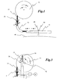
- Figure 1 shows a guide tube 41 placed along an object (not shown) that is to be sprayed.
- a forwardly and backwardly displaceable cartridge 42 is located in the guide tube 41, which cartridge is provided with one or several spray nozzles 43.
- the cartridge 42 is connected to a supply hose 11 for pressure medium or spray medium in the form of fluid, gaseous or solid, granule-formed or powder-formed material, such as, for example, water, air, cleaning fluid, paint, sand, etc.
- the cartridge 42 is driven along the guide tube 41 by the supply hose 11.
- the supply hose 11 is, in turn, driven forwards and backwards along its axial direction by means of three driving wheels 21 (one driving wheel is hidden in Figure 1).
- the driving wheels 21 will be described in more detail below, see Figures 2a and 2b.
- the supply hose 11 is driven in a forwards direction (f) it is dispensed from a hose magazine 31, and when it is driven in a backwards direction (b) it is collected onto the hose magazine 31.
- the hose magazine will be described in more detail below, see Figure 3.
- a scraper 12 is arranged between the driving wheels 21 and the guide tube 41, which scraper comprises at least one sealing arrangement (not shown in the drawing), which surrounds and seals the supply hose 11.
- a first aim of the scraper 12 is to scrape away any material/deposits from the supply hose 11 such that the friction between it and the driving wheels 21 is not degraded in such a manner that slipping occurs between the driving wheels 21 and the supply hose 11.
- a second aim of the scraper 12 is to make possible introduction into a pressurised vessel.
- a third aim of the scraper 12 is to make possible deflection of the supply hose 11 at an angle. Material/deposits may arise on the supply hose 11, since the present invention is used to clean a drum filter in the paper pulp industry.
- a drum filter is a drum with a perforated strainer plate on the jacket surface, which surface rotates during operation. Furthermore, the drum filter is placed into a vessel with added weak liquor and lime sludge (which contains slaked lime). The water-part of the contents of the vessel are sucked through the strainer plate by applying a vacuum to the inside of the drum, by which means what is known as a "precoat layer" is formed. i.e. material of the contents of the vessel.
- the guide tube 41 is applied along the drum.
- a cartridge 42 is moved, forwards and backwards with the aid of a supply hose 11 into the guide tube 41. Water under pressure is supplied through the supply hose 11 and is spayed through spray nozzles 43 for removal of precoat and for cleaning the strainer plate of the drum. Part of this material may thus become attached to the supply hose 11.
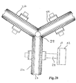
- FIGs 2a and 2b show an embodiment of the arrangement according to the invention for achieving an axial driving motion of the supply hose 11.
- the arrangement is characterised in that it comprises three driving wheels 21, where each driving wheel has a concave jacket surface 27 congruent with the supply hose 11.
- the concave jacket surface 27 surrounds the supply hose 11 around at least 100° degrees of the circumference of the supply hose 11.
- At least one of the driving wheels 21a is driven to rotate by driving means, preferably a motor.
- Figure 21 b shows an embodiment in which the axis 24 of the driving wheel 21 a is driven by a motor 52, preferably through a gear 51.
- the gear 51 is a drive belt between the axle 24 and the motor 52.
- each driving wheel 21 The outer sides of each driving wheel 21 are in physical contact with each other 29 in such a manner that the driving wheel 21a drives the other two driving wheels 21 b and 21 c through its rotation.
- An embodiment is shown in Figures 2a and 2b in which the outer jacket surfaces of the driving wheels 21 are provided with teeth 28 that enter into a shape-determined engagement with the teeth of a neighbouring driving wheel, and ensure that no slippage occurs between the driving wheels 21 when under driven rotation.
- Another embodiment (not shown) has instead of teeth plane surfaces with a high coefficient of friction ⁇ >0.8, preferably ⁇ >0.9, between the driving wheels 21 at their surfaces of contact 29.
- Figure 2a is shows an embodiment of the invention where the contact pressure between the driving wheels 21 and the supply hose 11 is controlled with the aid of three individually sprung elements 25, which are arranged to interact with the mounting of each driving wheel 21 through levers 23.
- the sprung element 25 is pressed upwards against the lever 23 such that the driving wheels are pressed in towards the supply hose 11. Since the mounting of the driving wheels is jointed 26 the bearings of the driving wheel will not be damaged if any radial unevenness or deformations are present in the supply hose 11, caused by a high working pressure in the supply hose 11.
- Figure 2a shows a preferred embodiment in which the sprung element 25 is constituted by a pneumatic cylinder in which the piston rod 25 makes contact with the lever 23.
- the driving wheel 21, or solely the concave jacket surfaces (27), are manufactured from a polymer material with a hardness that is equal to the hardness of the supply line 11, or preferably, lower than the hardness of the supply line 11.
- the coefficient of friction between the concave jacket surfaces 27 of the driving wheels 21 should be ⁇ >0.8 and preferably ⁇ >0.9.
- Figure 3 shows a hose magazine 31 onto which the supply hose 11 is rolled on and off.
- the supply hose 11 is driven in the forwards direction (f)
- the supply hose 11 is dispensed from the hose magazine, which in this case rotates in the direction (f) of unrolling.
- the supply hose 11 is driven in the backwards direction (b)
- the supply hose 11 is collected onto the hose magazine 31, which in this case rotates in the direction (b) of collection.
- a pulley wheel 32 is located at the centre of the hose magazine, arranged fixed relative to the hose magazine and rotating with it, onto which pulley a tension strap 33 is arranged.
- the tension strap 33 passes over a sprung element 34 and the tension strap is at its outer end fixed attached to an attachment 36, fixed in space.
- the sprung element has a low level (Fx) of force when the supply hose is driven in the forwards direction (f), and it has a high level (Fx) of force when the supply hose is driven in the backwards direction (b).
- Fx low level
- Fx high level
- the tension strap 33 is in this case wound up onto the pulley 32, which rotates with the hose magazine 31, and this means that the tension strap 33 presses down onto the sprung element 34.
- the tension strap 33 is maintained extended all the time, and ensures that the hose magazine 31 does not rotate too rapidly, rather that the supply hose 11 is maintained extended between the driving wheels 21 and the hose magazine 31.
- the driving wheels 21 drive the supply hose 11 in the backwards direction (b)
- the hose magazine is caused to rotate in the direction (b) of collection in that the sprung element 34 has a high level (Fx) of force directed in the direction (b) of collection such that the tension strap 33 rolls off from the pulley 32 which then starts to rotate with the hose magazine in the collection direction (b).
- the sprung element 34 which has a high level (Fx) of force, maintains the tension strap 33 extended and ensures that the hose magazine does not rotate too slowly, rather that the supply hose 11 is maintained extended between the driving wheels 21 and the hose magazine 31.
- Fx high level
- the sprung element 34 is constituted by a pneumatic cylinder in which the tension strap 33 makes contact with the piston rod 34.
- a sensor (s) detects whether the supply hose 11 is being driven in the forwards direction (i.e. the direction of dispensing (f) for the hose magazine) or in the backwards direction (i.e. the direction of collection (b) for the hose magazine).
- the signal from the sensor (s) is sent to a pressure valve (v) which is in turn connected to a pressure source (p).
- a pressure valve v
- the pressure valve (v) is opened, which causes a low level of force in the pneumatic cylinder.
- the pressure valve (v) is closed, which causes a high level of force in the pneumatic cylinder.
- FIG. 4 is shows a cross-section of an embodiment of a guide tube 41 placed along an object that is to be sprayed (not shown in the drawing).
- the guide tube 41 is manufactured from a polymer material and comprises a extended guide track 44 having the shape of a keyhole.
- a forwardly and backwardly displaceable cartridge 42 is arranged in the guide track 44.
- the cartridge 42 is equipped with one or several spray nozzles 43, and is connected to a supply hose 11.
- the cartridge 42 is displaced forwards and backwards in the guide tube 41 with the aid of the supply hose 11.
- the guide tube 41 is fixed and surrounded by an aluminium profile 45. It is appropriate in one embodiment in which water is used as application medium that the cartridge 42 is provided with lubrication channels 47 that provide a calibrated leakage flow of fluid that maintains the guide track 44 clean and reduces friction between the cartridge 42 and the guide track 44.
Landscapes
- Nozzles (AREA)
- Catching Or Destruction (AREA)
- Flexible Shafts (AREA)
- Electrical Discharge Machining, Electrochemical Machining, And Combined Machining (AREA)
- Spray Control Apparatus (AREA)
- Reciprocating Pumps (AREA)
- Earth Drilling (AREA)
- Coating Apparatus (AREA)
Applications Claiming Priority (2)
| Application Number | Priority Date | Filing Date | Title |
|---|---|---|---|
| SE0302076A SE525533C2 (sv) | 2003-07-14 | 2003-07-14 | Anordning för axiell drivning av tillförselslang |
| SE0302076 | 2003-07-14 |
Publications (3)
| Publication Number | Publication Date |
|---|---|
| EP1498188A2 true EP1498188A2 (de) | 2005-01-19 |
| EP1498188A3 EP1498188A3 (de) | 2007-11-21 |
| EP1498188B1 EP1498188B1 (de) | 2009-02-25 |
Family
ID=27764996
Family Applications (1)
| Application Number | Title | Priority Date | Filing Date |
|---|---|---|---|
| EP04075739A Expired - Lifetime EP1498188B1 (de) | 2003-07-14 | 2004-03-02 | Anordnung zum axialen Antrieb eines Zufuhrschlauchs |
Country Status (5)
| Country | Link |
|---|---|
| US (1) | US7401718B2 (de) |
| EP (1) | EP1498188B1 (de) |
| AT (1) | ATE423627T1 (de) |
| DE (1) | DE602004019604D1 (de) |
| SE (1) | SE525533C2 (de) |
Cited By (2)
| Publication number | Priority date | Publication date | Assignee | Title |
|---|---|---|---|---|
| CN106986240A (zh) * | 2017-05-11 | 2017-07-28 | 安徽理工大学 | 一种电动三路同步收放线装置 |
| CN111884129A (zh) * | 2020-08-26 | 2020-11-03 | 杨禹 | 一种建筑施工用电缆架设装置 |
Families Citing this family (6)
| Publication number | Priority date | Publication date | Assignee | Title |
|---|---|---|---|---|
| SG137753A1 (en) * | 2006-05-24 | 2007-12-28 | Inventio Ag | Elevator with frictional drive |
| US20080288004A1 (en) * | 2007-05-16 | 2008-11-20 | Genesis Biosystems Corporation | Tissue suspension device |
| WO2010132098A1 (en) * | 2009-05-10 | 2010-11-18 | Baker Solar, Inc. | Wafer handling device system and method |
| CN111570166A (zh) * | 2020-05-25 | 2020-08-25 | 安徽阜南县向发工艺品有限公司 | 一种木质地板表面喷漆设备及其工作方法 |
| CN118002385B (zh) * | 2024-04-01 | 2024-06-14 | 河北恒泰管道工程有限公司 | 一种防腐保温钢管喷涂装置 |
| CN119551766A (zh) * | 2024-11-22 | 2025-03-04 | 隶润科技(上海)有限公司 | 一种反渗透膜元件的水样探测系统及方法 |
Citations (5)
| Publication number | Priority date | Publication date | Assignee | Title |
|---|---|---|---|---|
| GB2037392A (en) | 1978-12-04 | 1980-07-09 | Homburg Machinehandel | Cleaning pipes |
| US4240017A (en) | 1977-07-21 | 1980-12-16 | Yoshino Kogyosho Co., Ltd. | Control method in an intermittently moving mechanism and a shift register for carrying out the method |
| US4592282A (en) | 1984-07-10 | 1986-06-03 | Luossavaara-Kiirunavaara Aktiebolag | Charging apparatus for cartridged explosives |
| SE502317C2 (sv) | 1994-09-22 | 1995-10-02 | Rolf Baerekrans | Anordning för styrning av sprutmunstycken |
| JP2001300458A (ja) | 2000-04-20 | 2001-10-30 | Yutaka Kiko Kk | 管洗浄装置及び洗浄方法 |
Family Cites Families (13)
| Publication number | Priority date | Publication date | Assignee | Title |
|---|---|---|---|---|
| US1759105A (en) * | 1928-09-07 | 1930-05-20 | Charles S Knight | Die for laying wire rope and wire-rope strands |
| NL6814678A (de) * | 1968-10-14 | 1970-04-16 | ||
| US4054128A (en) * | 1976-09-28 | 1977-10-18 | Universite De Sherbrooke | Device for carrying observation and/or manipulation instruments |
| DE2861887D1 (en) * | 1978-06-13 | 1982-07-29 | Plumettaz Sa | Cable conveyor |
| JP2750497B2 (ja) * | 1993-11-30 | 1998-05-13 | モレックス インコーポレーテッド | 複数の電線の測長装置 |
| NL194836C (nl) * | 1995-03-10 | 2003-04-03 | Allseas Group Sa | Inrichting voor het leggen van een pijpleiding op een onder water gelegen bodem. |
| US5934537A (en) * | 1997-01-22 | 1999-08-10 | Miller; James Edwin | Device for pushing or pulling using gripping |
| NL1005992C2 (nl) * | 1997-05-06 | 1998-11-09 | Itrec Bv | Tensioner. |
| WO1998051510A1 (en) * | 1997-05-15 | 1998-11-19 | Datamax Corporation | Pulley tensioner |
| EP1134174A4 (de) * | 1998-07-10 | 2002-02-06 | Takako Yasui | Förderer, fördererantrieb sowie anwendung des förderers |
| US7021510B2 (en) * | 2004-02-12 | 2006-04-04 | David Irwin Ellingson | Cable traction apparatus and method |
| US7338004B2 (en) * | 2004-10-18 | 2008-03-04 | Kurt W. Niederer | Let-off device with constant tension |
| EP1705413B1 (de) * | 2005-03-21 | 2007-07-04 | Ottmar Diehl | Rohrspanngerät |
-
2003
- 2003-07-14 SE SE0302076A patent/SE525533C2/sv not_active IP Right Cessation
-
2004
- 2004-02-23 US US10/784,455 patent/US7401718B2/en not_active Expired - Fee Related
- 2004-03-02 EP EP04075739A patent/EP1498188B1/de not_active Expired - Lifetime
- 2004-03-02 AT AT04075739T patent/ATE423627T1/de active
- 2004-03-02 DE DE602004019604T patent/DE602004019604D1/de not_active Expired - Lifetime
Patent Citations (5)
| Publication number | Priority date | Publication date | Assignee | Title |
|---|---|---|---|---|
| US4240017A (en) | 1977-07-21 | 1980-12-16 | Yoshino Kogyosho Co., Ltd. | Control method in an intermittently moving mechanism and a shift register for carrying out the method |
| GB2037392A (en) | 1978-12-04 | 1980-07-09 | Homburg Machinehandel | Cleaning pipes |
| US4592282A (en) | 1984-07-10 | 1986-06-03 | Luossavaara-Kiirunavaara Aktiebolag | Charging apparatus for cartridged explosives |
| SE502317C2 (sv) | 1994-09-22 | 1995-10-02 | Rolf Baerekrans | Anordning för styrning av sprutmunstycken |
| JP2001300458A (ja) | 2000-04-20 | 2001-10-30 | Yutaka Kiko Kk | 管洗浄装置及び洗浄方法 |
Cited By (3)
| Publication number | Priority date | Publication date | Assignee | Title |
|---|---|---|---|---|
| CN106986240A (zh) * | 2017-05-11 | 2017-07-28 | 安徽理工大学 | 一种电动三路同步收放线装置 |
| CN106986240B (zh) * | 2017-05-11 | 2018-01-30 | 安徽理工大学 | 一种电动三路同步收放线装置 |
| CN111884129A (zh) * | 2020-08-26 | 2020-11-03 | 杨禹 | 一种建筑施工用电缆架设装置 |
Also Published As
| Publication number | Publication date |
|---|---|
| DE602004019604D1 (de) | 2009-04-09 |
| SE525533C2 (sv) | 2005-03-08 |
| US20050011969A1 (en) | 2005-01-20 |
| ATE423627T1 (de) | 2009-03-15 |
| US7401718B2 (en) | 2008-07-22 |
| SE0302076D0 (sv) | 2003-07-14 |
| EP1498188A3 (de) | 2007-11-21 |
| SE0302076L (sv) | 2005-01-15 |
| EP1498188B1 (de) | 2009-02-25 |
Similar Documents
| Publication | Publication Date | Title |
|---|---|---|
| EP2139621B1 (de) | Reinigungsvorrichtung für rohre mit grossem durchmesser | |
| EP1498188B1 (de) | Anordnung zum axialen Antrieb eines Zufuhrschlauchs | |
| KR101131472B1 (ko) | 노후관로 내면 연마장치 | |
| US6158074A (en) | Pipe cleaning machine | |
| US5352298A (en) | Tank car cleaning and stripping apparatus and method | |
| EP0042207B1 (de) | Verfahren und Vorrichtung zum Innenbeschichten langer Rohre mit kleinem Durchmesser | |
| US5549305A (en) | Sootblower packing gland | |
| CA2017972C (en) | High pressure water jet cleaner and coating applicator | |
| KR20090055119A (ko) | 노후관로의 스케일 제거장치 | |
| CA2490508A1 (en) | Cleaning rolls, cylinders and printing forms by jet of frozen particles | |
| IT201800006425A1 (it) | Apparecchio per la pulizia di rulli cilindrici, macchina comprendente detto apparecchio, e metodo di pulizia | |
| US5577293A (en) | Full recovery stripping system | |
| CA2261085C (en) | High pressure reciprocating suction roll shower | |
| KR101193801B1 (ko) | 중대형 노후 상수 관로 내면의 세척장치 | |
| WO2002087794A1 (en) | Equipment for external cleaning of tubes with fluid under pressure | |
| EP3678794B1 (de) | Industrielle anlage mit einem kontaktlosen wischer | |
| GB2044133A (en) | Cleaning a coating roll | |
| JPH03229663A (ja) | 鋼管内面塗油方法及び装置 | |
| CN211707632U (zh) | 一种管道清洁机器人 | |
| KR200242526Y1 (ko) | 오일제거장치 | |
| US4433639A (en) | Application for spraying liquid chemical onto drill pipe | |
| CN110778807B (zh) | 一种耐腐蚀不锈钢管及其矫直机 | |
| KR20180116587A (ko) | 차선도포기 | |
| KR100199070B1 (ko) | 국부적 페인트 연속 제거장치 | |
| CN219632024U (zh) | 一种胶辊清理机构 |
Legal Events
| Date | Code | Title | Description |
|---|---|---|---|
| PUAI | Public reference made under article 153(3) epc to a published international application that has entered the european phase |
Free format text: ORIGINAL CODE: 0009012 |
|
| AK | Designated contracting states |
Kind code of ref document: A2 Designated state(s): AT BE BG CH CY CZ DE DK EE ES FI FR GB GR HU IE IT LI LU MC NL PL PT RO SE SI SK TR |
|
| AX | Request for extension of the european patent |
Extension state: AL HR LT LV MK |
|
| RAP1 | Party data changed (applicant data changed or rights of an application transferred) |
Owner name: METSO FIBER KARLSTAD AB |
|
| PUAL | Search report despatched |
Free format text: ORIGINAL CODE: 0009013 |
|
| AK | Designated contracting states |
Kind code of ref document: A3 Designated state(s): AT BE BG CH CY CZ DE DK EE ES FI FR GB GR HU IE IT LI LU MC NL PL PT RO SE SI SK TR |
|
| AX | Request for extension of the european patent |
Extension state: AL LT LV MK |
|
| 17P | Request for examination filed |
Effective date: 20080521 |
|
| AKX | Designation fees paid |
Designated state(s): AT BE BG CH CY CZ DE DK EE ES FI FR GB GR HU IE IT LI LU MC NL PL PT RO SE SI SK TR |
|
| GRAP | Despatch of communication of intention to grant a patent |
Free format text: ORIGINAL CODE: EPIDOSNIGR1 |
|
| GRAS | Grant fee paid |
Free format text: ORIGINAL CODE: EPIDOSNIGR3 |
|
| GRAA | (expected) grant |
Free format text: ORIGINAL CODE: 0009210 |
|
| AK | Designated contracting states |
Kind code of ref document: B1 Designated state(s): AT BE BG CH CY CZ DE DK EE ES FI FR GB GR HU IE IT LI LU MC NL PL PT RO SE SI SK TR |
|
| REG | Reference to a national code |
Ref country code: GB Ref legal event code: FG4D |
|
| REG | Reference to a national code |
Ref country code: CH Ref legal event code: EP |
|
| REG | Reference to a national code |
Ref country code: IE Ref legal event code: FG4D |
|
| REF | Corresponds to: |
Ref document number: 602004019604 Country of ref document: DE Date of ref document: 20090409 Kind code of ref document: P |
|
| REG | Reference to a national code |
Ref country code: SE Ref legal event code: TRGR |
|
| PG25 | Lapsed in a contracting state [announced via postgrant information from national office to epo] |
Ref country code: SI Free format text: LAPSE BECAUSE OF FAILURE TO SUBMIT A TRANSLATION OF THE DESCRIPTION OR TO PAY THE FEE WITHIN THE PRESCRIBED TIME-LIMIT Effective date: 20090225 Ref country code: NL Free format text: LAPSE BECAUSE OF FAILURE TO SUBMIT A TRANSLATION OF THE DESCRIPTION OR TO PAY THE FEE WITHIN THE PRESCRIBED TIME-LIMIT Effective date: 20090225 Ref country code: FI Free format text: LAPSE BECAUSE OF FAILURE TO SUBMIT A TRANSLATION OF THE DESCRIPTION OR TO PAY THE FEE WITHIN THE PRESCRIBED TIME-LIMIT Effective date: 20090225 |
|
| NLV1 | Nl: lapsed or annulled due to failure to fulfill the requirements of art. 29p and 29m of the patents act | ||
| PG25 | Lapsed in a contracting state [announced via postgrant information from national office to epo] |
Ref country code: PL Free format text: LAPSE BECAUSE OF FAILURE TO SUBMIT A TRANSLATION OF THE DESCRIPTION OR TO PAY THE FEE WITHIN THE PRESCRIBED TIME-LIMIT Effective date: 20090225 |
|
| PG25 | Lapsed in a contracting state [announced via postgrant information from national office to epo] |
Ref country code: BE Free format text: LAPSE BECAUSE OF FAILURE TO SUBMIT A TRANSLATION OF THE DESCRIPTION OR TO PAY THE FEE WITHIN THE PRESCRIBED TIME-LIMIT Effective date: 20090225 |
|
| PG25 | Lapsed in a contracting state [announced via postgrant information from national office to epo] |
Ref country code: DK Free format text: LAPSE BECAUSE OF FAILURE TO SUBMIT A TRANSLATION OF THE DESCRIPTION OR TO PAY THE FEE WITHIN THE PRESCRIBED TIME-LIMIT Effective date: 20090225 Ref country code: CZ Free format text: LAPSE BECAUSE OF FAILURE TO SUBMIT A TRANSLATION OF THE DESCRIPTION OR TO PAY THE FEE WITHIN THE PRESCRIBED TIME-LIMIT Effective date: 20090225 Ref country code: EE Free format text: LAPSE BECAUSE OF FAILURE TO SUBMIT A TRANSLATION OF THE DESCRIPTION OR TO PAY THE FEE WITHIN THE PRESCRIBED TIME-LIMIT Effective date: 20090225 Ref country code: ES Free format text: LAPSE BECAUSE OF FAILURE TO SUBMIT A TRANSLATION OF THE DESCRIPTION OR TO PAY THE FEE WITHIN THE PRESCRIBED TIME-LIMIT Effective date: 20090605 Ref country code: PT Free format text: LAPSE BECAUSE OF FAILURE TO SUBMIT A TRANSLATION OF THE DESCRIPTION OR TO PAY THE FEE WITHIN THE PRESCRIBED TIME-LIMIT Effective date: 20090812 Ref country code: MC Free format text: LAPSE BECAUSE OF NON-PAYMENT OF DUE FEES Effective date: 20090331 |
|
| REG | Reference to a national code |
Ref country code: CH Ref legal event code: PL |
|
| PG25 | Lapsed in a contracting state [announced via postgrant information from national office to epo] |
Ref country code: SK Free format text: LAPSE BECAUSE OF FAILURE TO SUBMIT A TRANSLATION OF THE DESCRIPTION OR TO PAY THE FEE WITHIN THE PRESCRIBED TIME-LIMIT Effective date: 20090225 Ref country code: RO Free format text: LAPSE BECAUSE OF FAILURE TO SUBMIT A TRANSLATION OF THE DESCRIPTION OR TO PAY THE FEE WITHIN THE PRESCRIBED TIME-LIMIT Effective date: 20090225 |
|
| PLBE | No opposition filed within time limit |
Free format text: ORIGINAL CODE: 0009261 |
|
| STAA | Information on the status of an ep patent application or granted ep patent |
Free format text: STATUS: NO OPPOSITION FILED WITHIN TIME LIMIT |
|
| GBPC | Gb: european patent ceased through non-payment of renewal fee |
Effective date: 20090525 |
|
| PG25 | Lapsed in a contracting state [announced via postgrant information from national office to epo] |
Ref country code: LI Free format text: LAPSE BECAUSE OF NON-PAYMENT OF DUE FEES Effective date: 20090331 Ref country code: IE Free format text: LAPSE BECAUSE OF NON-PAYMENT OF DUE FEES Effective date: 20090302 Ref country code: CH Free format text: LAPSE BECAUSE OF NON-PAYMENT OF DUE FEES Effective date: 20090331 Ref country code: BG Free format text: LAPSE BECAUSE OF FAILURE TO SUBMIT A TRANSLATION OF THE DESCRIPTION OR TO PAY THE FEE WITHIN THE PRESCRIBED TIME-LIMIT Effective date: 20090525 |
|
| 26N | No opposition filed |
Effective date: 20091126 |
|
| PG25 | Lapsed in a contracting state [announced via postgrant information from national office to epo] |
Ref country code: GB Free format text: LAPSE BECAUSE OF NON-PAYMENT OF DUE FEES Effective date: 20090525 |
|
| PG25 | Lapsed in a contracting state [announced via postgrant information from national office to epo] |
Ref country code: FR Free format text: LAPSE BECAUSE OF NON-PAYMENT OF DUE FEES Effective date: 20090427 Ref country code: GR Free format text: LAPSE BECAUSE OF FAILURE TO SUBMIT A TRANSLATION OF THE DESCRIPTION OR TO PAY THE FEE WITHIN THE PRESCRIBED TIME-LIMIT Effective date: 20090526 |
|
| REG | Reference to a national code |
Ref country code: FR Ref legal event code: ST Effective date: 20100930 |
|
| PG25 | Lapsed in a contracting state [announced via postgrant information from national office to epo] |
Ref country code: IT Free format text: LAPSE BECAUSE OF FAILURE TO SUBMIT A TRANSLATION OF THE DESCRIPTION OR TO PAY THE FEE WITHIN THE PRESCRIBED TIME-LIMIT Effective date: 20090225 |
|
| PG25 | Lapsed in a contracting state [announced via postgrant information from national office to epo] |
Ref country code: LU Free format text: LAPSE BECAUSE OF NON-PAYMENT OF DUE FEES Effective date: 20090302 |
|
| REG | Reference to a national code |
Ref country code: DE Ref legal event code: R081 Ref document number: 602004019604 Country of ref document: DE Owner name: METSO PAPER SWEDEN AB, SE Free format text: FORMER OWNER: METSO FIBER KARLSTAD AB, KARLSTAD, SE Effective date: 20110420 |
|
| PG25 | Lapsed in a contracting state [announced via postgrant information from national office to epo] |
Ref country code: HU Free format text: LAPSE BECAUSE OF FAILURE TO SUBMIT A TRANSLATION OF THE DESCRIPTION OR TO PAY THE FEE WITHIN THE PRESCRIBED TIME-LIMIT Effective date: 20090826 |
|
| PG25 | Lapsed in a contracting state [announced via postgrant information from national office to epo] |
Ref country code: TR Free format text: LAPSE BECAUSE OF FAILURE TO SUBMIT A TRANSLATION OF THE DESCRIPTION OR TO PAY THE FEE WITHIN THE PRESCRIBED TIME-LIMIT Effective date: 20090225 |
|
| PG25 | Lapsed in a contracting state [announced via postgrant information from national office to epo] |
Ref country code: CY Free format text: LAPSE BECAUSE OF FAILURE TO SUBMIT A TRANSLATION OF THE DESCRIPTION OR TO PAY THE FEE WITHIN THE PRESCRIBED TIME-LIMIT Effective date: 20090225 |
|
| REG | Reference to a national code |
Ref country code: AT Ref legal event code: PC Ref document number: 423627 Country of ref document: AT Kind code of ref document: T Owner name: METSO PAPER SWEDEN AKTIEBOLAG, SE Effective date: 20111223 |
|
| PGFP | Annual fee paid to national office [announced via postgrant information from national office to epo] |
Ref country code: SE Payment date: 20170321 Year of fee payment: 14 Ref country code: DE Payment date: 20170322 Year of fee payment: 14 |
|
| PGFP | Annual fee paid to national office [announced via postgrant information from national office to epo] |
Ref country code: AT Payment date: 20170322 Year of fee payment: 14 |
|
| REG | Reference to a national code |
Ref country code: DE Ref legal event code: R119 Ref document number: 602004019604 Country of ref document: DE |
|
| PG25 | Lapsed in a contracting state [announced via postgrant information from national office to epo] |
Ref country code: SE Free format text: LAPSE BECAUSE OF NON-PAYMENT OF DUE FEES Effective date: 20180303 |
|
| REG | Reference to a national code |
Ref country code: AT Ref legal event code: MM01 Ref document number: 423627 Country of ref document: AT Kind code of ref document: T Effective date: 20180302 |
|
| PG25 | Lapsed in a contracting state [announced via postgrant information from national office to epo] |
Ref country code: DE Free format text: LAPSE BECAUSE OF NON-PAYMENT OF DUE FEES Effective date: 20181002 Ref country code: AT Free format text: LAPSE BECAUSE OF NON-PAYMENT OF DUE FEES Effective date: 20180302 |