EP1498218B1 - Procédé de fabrication d'un élément fonctionnel à construction légère et élément fonctionnel à construction légère - Google Patents
Procédé de fabrication d'un élément fonctionnel à construction légère et élément fonctionnel à construction légère Download PDFInfo
- Publication number
- EP1498218B1 EP1498218B1 EP04450144A EP04450144A EP1498218B1 EP 1498218 B1 EP1498218 B1 EP 1498218B1 EP 04450144 A EP04450144 A EP 04450144A EP 04450144 A EP04450144 A EP 04450144A EP 1498218 B1 EP1498218 B1 EP 1498218B1
- Authority
- EP
- European Patent Office
- Prior art keywords
- bearing part
- recess
- main body
- light
- bearing
- Prior art date
- Legal status (The legal status is an assumption and is not a legal conclusion. Google has not performed a legal analysis and makes no representation as to the accuracy of the status listed.)
- Expired - Lifetime
Links
- 238000004519 manufacturing process Methods 0.000 title claims description 10
- 238000010276 construction Methods 0.000 title description 3
- 238000000034 method Methods 0.000 claims abstract description 10
- 238000003780 insertion Methods 0.000 claims abstract description 5
- 230000037431 insertion Effects 0.000 claims abstract description 5
- 229910052751 metal Inorganic materials 0.000 claims abstract description 5
- 239000002184 metal Substances 0.000 claims abstract description 5
- 238000005266 casting Methods 0.000 claims description 5
- 238000003825 pressing Methods 0.000 claims description 5
- FYYHWMGAXLPEAU-UHFFFAOYSA-N Magnesium Chemical compound [Mg] FYYHWMGAXLPEAU-UHFFFAOYSA-N 0.000 abstract description 3
- 229910052782 aluminium Inorganic materials 0.000 abstract description 3
- XAGFODPZIPBFFR-UHFFFAOYSA-N aluminium Chemical compound [Al] XAGFODPZIPBFFR-UHFFFAOYSA-N 0.000 abstract description 3
- 239000011777 magnesium Substances 0.000 abstract description 3
- 229910052749 magnesium Inorganic materials 0.000 abstract description 3
- 239000004411 aluminium Substances 0.000 abstract 1
- 230000002093 peripheral effect Effects 0.000 description 7
- 238000013461 design Methods 0.000 description 2
- 230000002349 favourable effect Effects 0.000 description 2
- 239000000463 material Substances 0.000 description 2
- 238000003860 storage Methods 0.000 description 2
- 229910000831 Steel Inorganic materials 0.000 description 1
- 150000001875 compounds Chemical class 0.000 description 1
- 239000002826 coolant Substances 0.000 description 1
- 238000004512 die casting Methods 0.000 description 1
- 238000012805 post-processing Methods 0.000 description 1
- 239000010959 steel Substances 0.000 description 1
- 238000012549 training Methods 0.000 description 1
- 230000007704 transition Effects 0.000 description 1
- 239000013585 weight reducing agent Substances 0.000 description 1
Images
Classifications
-
- B—PERFORMING OPERATIONS; TRANSPORTING
- B21—MECHANICAL METAL-WORKING WITHOUT ESSENTIALLY REMOVING MATERIAL; PUNCHING METAL
- B21K—MAKING FORGED OR PRESSED METAL PRODUCTS, e.g. HORSE-SHOES, RIVETS, BOLTS OR WHEELS
- B21K25/00—Uniting components to form integral members, e.g. turbine wheels and shafts, caulks with inserts, with or without shaping of the components
-
- B—PERFORMING OPERATIONS; TRANSPORTING
- B23—MACHINE TOOLS; METAL-WORKING NOT OTHERWISE PROVIDED FOR
- B23P—METAL-WORKING NOT OTHERWISE PROVIDED FOR; COMBINED OPERATIONS; UNIVERSAL MACHINE TOOLS
- B23P11/00—Connecting or disconnecting metal parts or objects by metal-working techniques not otherwise provided for
-
- B—PERFORMING OPERATIONS; TRANSPORTING
- B23—MACHINE TOOLS; METAL-WORKING NOT OTHERWISE PROVIDED FOR
- B23P—METAL-WORKING NOT OTHERWISE PROVIDED FOR; COMBINED OPERATIONS; UNIVERSAL MACHINE TOOLS
- B23P15/00—Making specific metal objects by operations not covered by a single other subclass or a group in this subclass
Definitions
- the present invention relates to a method according to the preamble of claim 1 and a lightweight functional part according to the preamble of claim 6.
- Automotive engineering is increasingly using lightweight functional parts to reduce vehicle weight. These are generally components that are to transmit or absorb mechanical loads, such as a holder for a handbrake lever, a load-bearing component of a vehicle seat or a housing for a coolant pump.
- the production of such components in the aluminum or magnesium die-casting process makes it possible to achieve a considerable weight reduction with predetermined strength properties.
- due to the specific material properties of these aluminum or magnesium components it is necessary to pay particular attention to the portions where high loads are introduced, as is the case where larger forces are introduced, such as at the locations which other components, such as levers, are mounted movably or rigidly on the functional part.
- Another important aspect in the construction of such components is the simplest possible structure, which allows cost-effective production in large quantities.
- rivets which have a partially toothed shaft area in order to achieve a safeguard against falling out.
- Examples of such rivets are in the US 6,357,955 A , of the EP 0 857 843 A , of the US 3,390,419 A , of the US 5,577,295 A or the GB 2 134 859 A described.
- These solutions are rivets intended for steel or plastic components. Compounds of this type are not readily usable for light metal components.
- a mechanically particularly favored embodiment can be achieved if the pressing in takes place until a first end face of the bearing part rests against the base surface of the recess. As a result, the control of the press-fitting process is very simplified because it is pressed to the stop.
- the bearing part is fixed in the passage opening-for example by wobble riveting-whereby the further component protrudes into an exemption of the passage opening and is thus freely movable.
- the slope of the side walls of the recess is favorably in a range between 10% and 15%.
- a mechanically particularly favorable solution provides that the bearing part has a pin which is held in the passage opening of the base body.
- forces and moments can be optimally absorbed when the pin has a first portion which is held in the passage opening of the base body with a press fit and when a second portion of the pin serves as a bearing point for the further component.
- the axial passage opening in the region of the second portion of the pin on an exemption.
- the recess has a lower inner diameter at the bottom of the recess, which is smaller than the outer diameter of the cylindrical peripheral surface of the bearing part and when the recess has an upper inner diameter in the region of the opening of the recess, which is greater than the outer diameter of the recess is particularly advantageous cylindrical peripheral surface of the bearing part. Due to the geometric design, it is possible to connect the parts together, even if they are not initially aligned exactly.
- the occurrence of impermissibly high stresses in the functional part can be avoided if the toothing of the bearing part has a depth that is greater than half the difference between the outer diameter of the cylindrical peripheral surface of the bearing part and the lower inner diameter at the bottom of the recess. In this way it is ensured that the displaced by the toothing material can at least partially penetrate into the interdental spaces, whereby a positive and frictional connection is made.
- a particularly simple production is achieved in that the recess is unprocessed, i. is produced by a casting process and any reworking is omitted.
- a mechanically particularly favored solution provides that the bearing part consists of a disc and a pin formed thereon, and that the toothing is provided on the peripheral surface of the disc. In this way, the forces can be introduced into the functional part so that only small stresses occur at the interface. The moments occurring at the teeth can be kept so small.
- the disc has an outer diameter which is at least three times as large as the dimension of the disc in the axial direction and when the disc has an outer diameter which is greater than the dimension of the bearing member in the axial direction.
- the manufacturing costs can be minimized if the bearing part is cold-pressed.
- the teeth can be made directly. Alternatively, the teeth of the bearing part can be made by knurling.
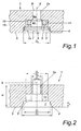
- the in Fig. 1 shown functional part has a base body 1 with a recess 2, the in Fig. 2 can be seen on an enlarged scale.
- the recess 2 has a flat base 3 and a frustoconical peripheral surface 4.
- the base 3 has a diameter D 1 , which is referred to here as the lower inner diameter.
- the recess 2 has a diameter D 2 , which is referred to herein as the upper inner diameter.
- the depth of the recess 2 is designated by t.
- the recess 2 continues in a passage opening 2a, which has a significantly smaller diameter D 4 .
- the component thickness w at this point represents the total length of the recess 2 and through opening 2a.
- a bearing part 6 is pressed, which consists of a disc 7 with an outer diameter D 3 , which has a toothing 7a at its periphery.
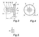
- the dimension of the disc 7 in the direction of the axis 8 is denoted by a (see Fig. 3 ).
- a first end face 15 of the bearing part 6 rests on the base 3 of the recess 2.
- the disc 7 is in the axial direction of a pin 9, which has a first portion 9a and a second portion 9b with a slightly larger diameter having.
- the second section 9b has a bearing surface 13 which serves to receive a further, here only indicated, component 10.
- the first portion 9a is fixed in the through-hole 2a, for example, by wobble riveting.
- the axial passage opening 2a has in the region of the second portion 9b of the pin 9 an exemption 11 with a diameter D5 to give the component 10 in the storage area the necessary freedom of movement.
- the diameter D6 in the transition region between the recess 2 and the exemption 11 is less than / equal to D5, so that the variant indicated by dashed lines is possible.
- the bearing part 6 is pressed from the side of a second end face 12 in the recess 2, wherein a central recess 14 in the second end face 12 serves for centering.
- the dimension b of the bearing part 6 in the direction of the axis 8 is smaller than the outer diameter D 3 of the disc 7.
- the toothing 7a has a depth s.
- a recess 16 is provided, which serves to produce a riveted joint with the base body 1.
- Typical dimensions of the individual components are: Lower inner diameter D 1 : 16.0 mm; Upper inner diameter D 2 : 17.5 mm; Diameter D 4 of the passage opening 9.0 mm; Depth t of the recess 2: 6.0 mm; Diameter D 3 of the disc 7: 17.0 mm; Depth s of toothing 7a: 0.7 mm; Dimension a of the disc 7: 5.5 mm; Dimension b of the bearing part 6: 15.0 mm;
Landscapes
- Engineering & Computer Science (AREA)
- Mechanical Engineering (AREA)
- Mounting Of Bearings Or Others (AREA)
- Body Structure For Vehicles (AREA)
- Golf Clubs (AREA)
- Forging (AREA)
- Metal Extraction Processes (AREA)
- Motor Or Generator Frames (AREA)
- Shafts, Cranks, Connecting Bars, And Related Bearings (AREA)
Claims (13)
- Procédé de fabrication d'une pièce fonctionnelle, en construction légère, ayant un corps de base (1) fabriqué par un procédé d'injection sous pression de métal léger et une pièce de palier (6) dans le corps de base (1), selon lequel
lors de la coulée on réalise une cavité (2) ayant une section conique allant en s'élargissant vers l'ouverture et se poursuivant axialement par un orifice traversant (2a) de diamètre (D4) plus petit et
la cavité (2) de la partie de palier (6) comporte de préférence un rivet, enfoncé de force, ayant une surface périphérique avec une denture (7a) qui pénètre dans la surface périphérique (4) de la cavité (2),
caractérisé en ce qu'
un autre composant (10) est mis en liaison avec la partie de palier (6) dans un dégagement (11) de l'orifice traversant (2a) du corps de base (1) avec la partie formant palier (6), pour recevoir l'autre composant (10) et la surface périphérique de la denture (7a) est pratiquement cylindrique. - Procédé selon la revendication 1,
caractérisé en ce que
l'enfoncement de force se fait jusqu'à ce qu'une première surface frontale (15) de la pièce de palier (6) s'appuie contre la surface de base (3) de la cavité (2) et
l'introduction de la pièce de palier (6) se fait initialement avec du jeu et la pièce de palier (6) vient en prise avec la surface périphérique (4) de la cavité (2) seulement pendant l'introduction. - Procédé selon l'une des revendications 1 et 2,
caractérisé en ce que
la fabrication de la pièce de palier (6) se fait par une opération de pressage à froid. - Procédé selon l'une des revendications 1 à 3,
caractérisé en ce que
lors du pressage la pièce de palier (6) est tenue de manière mobile, limitée radialement par rapport au corps de base (1) et lorsqu'on comprime, elle est centrée par une broche qui vient dans la cavité centrale (14) de la seconde face frontale (12). - Procédé selon l'une des revendications 1 à 3,
caractérisé en ce que
la pièce de palier (6) est fixée dans l'orifice traversant (2a) par exemple par des rivets de nutation et l'autre pièce (10) pénètre dans le dégagement (11) de l'orifice traversant (2a). - Pièce fonctionnelle en construction légère ayant un corps de base (1) fabriqué par un procédé d'injection sous pression de métal léger et une pièce de palier (6) installée dans le corps de base (1),
le corps de base (1) ayant au moins une cavité (2) avec une surface périphérique (4) pratiquement en forme de tronc de cône s'élargissant en direction de l'ouverture, et se poursuivant axialement par un orifice traversant (2a) de diamètre (D4) plus petit et
la pièce de palier (6) comporte de préférence un rivet dont la surface périphérique est munie d'une denture (7a) et
la surface périphérique cylindrique de la pièce de palier (6) est enfoncée de force dans la surface périphérique (4) en forme de tronc de cône de la cavité (2) du corps de base (1),
caractérisée en ce que
l'orifice traversant axial (2a) du corps de base (1) comporte un dégagement (11) pour recevoir un autre composant (10) en liaison avec la pièce de palier, et
la surface périphérique a pratiquement une forme cylindrique avec la denture (7a). - Pièce fonctionnelle en construction légère selon la revendication 6,
caractérisée en ce que
la pièce de palier (6) comporte un goujon (9) tenu dans l'orifice traversant (2a) du corps de base (1) et
le goujon (9) comporte de préférence un premier segment (9a) tenu par un ajustage pressé dans l'orifice traversant (2a) du corps de base (1) et
un second segment (9b) du goujon (9) sert de palier pour l'autre composant (10). - Pièce fonctionnelle en construction légère selon l'une des revendications 6 ou 7,
caractérisée en ce que
la cavité (2) a un diamètre intérieur, inférieur, (D1) au fond de la cavité (2) qui est inférieur du diamètre extérieur (D3) de la surface périphérique cylindrique de la pièce de palier (6) et
la cavité (2) a un diamètre intérieur, supérieur, (D2) au niveau de l'orifice de la cavité (2) et supérieur au diamètre extérieur (D3) de la surface périphérique cylindrique de la pièce de palier (6). - Pièce fonctionnelle en construction légère selon la revendication 8,
caractérisée en ce que
la denture de la pièce de palier (6) a une profondeur (s) supérieure à la demi-différence entre le diamètre extérieur (D3) de la surface périphérique cylindrique (7) de la pièce de palier (6) et le diamètre intérieur inférieur (D1) au fond de la cavité (2). - Pièce fonctionnelle en construction légère selon l'une des revendications 6 à 9,
caractérisée en ce que
la pièce de palier (6) se compose d'un disque (7) et d'un téton (9) formé sur celui-ci et
la denture (7a) est prévue sur la surface périphérique du disque (7) et
la pièce de palier (6) a une première surface frontale (5) qui s'appuie sur une surface de base (3) de la cavité (2). - Pièce fonctionnelle en construction légère selon la revendication 10,
caractérisée en ce que
le disque (7) a un diamètre extérieur (D3) qui est au moins trois fois aussi grand que la dimension (a) du disque (7) dans la direction axiale et de préférence il est supérieur à la dimension (b) de la pièce de palier (6) dans la direction axiale. - Pièce fonctionnelle en construction légère selon l'une des revendications 6 à 11,
caractérisée en ce que
la pièce de palier (6) est pressée à froid. - Pièce fonctionnelle en construction légère selon l'une des revendications 6 à 12,
caractérisée en ce qu'
à l'extrémité du téton (9) il est prévu une auxtre cavité centrale (11) servant à la réalisation d'une liaison par la forme avec l'autre pièce de palier (10).
Applications Claiming Priority (2)
| Application Number | Priority Date | Filing Date | Title |
|---|---|---|---|
| AT0112403A AT412990B8 (de) | 2003-07-17 | 2003-07-17 | Verfahren zur herstellung eines leichtbau-funktionsteils und leichtbau-funktionsteil |
| AT11242003 | 2003-07-17 |
Publications (3)
| Publication Number | Publication Date |
|---|---|
| EP1498218A2 EP1498218A2 (fr) | 2005-01-19 |
| EP1498218A3 EP1498218A3 (fr) | 2005-07-13 |
| EP1498218B1 true EP1498218B1 (fr) | 2008-05-28 |
Family
ID=33459534
Family Applications (1)
| Application Number | Title | Priority Date | Filing Date |
|---|---|---|---|
| EP04450144A Expired - Lifetime EP1498218B1 (fr) | 2003-07-17 | 2004-07-14 | Procédé de fabrication d'un élément fonctionnel à construction légère et élément fonctionnel à construction légère |
Country Status (3)
| Country | Link |
|---|---|
| EP (1) | EP1498218B1 (fr) |
| AT (2) | AT412990B8 (fr) |
| DE (1) | DE502004007263D1 (fr) |
Family Cites Families (13)
| Publication number | Priority date | Publication date | Assignee | Title |
|---|---|---|---|---|
| US3390419A (en) * | 1965-11-05 | 1968-07-02 | Lawrence Brothers | Flush mounted arrangement of a hinge pintle |
| US3734697A (en) * | 1970-07-13 | 1973-05-22 | Roth Co Roy E | Pump impeller making |
| US4220052A (en) * | 1979-05-25 | 1980-09-02 | Rexnord Inc. | Pin retention by interference fit differential |
| NO803668L (no) * | 1980-12-04 | 1982-06-07 | Raufoss Ammunisjonsfabrikker | Element av metall, samt fremgangsmaate for dets fremstilling |
| GB2134859B (en) * | 1983-02-08 | 1986-08-20 | York Technical Services Limite | Road vehicle suspensions |
| US4750851A (en) * | 1987-07-15 | 1988-06-14 | Dyneer Corporation | Self-aligning pivot bolt |
| DE3939530A1 (de) * | 1989-11-30 | 1991-06-06 | Bayerische Motoren Werke Ag | Tuerbremse fuer kraftfahrzeuge |
| DE4033216C2 (de) * | 1990-10-19 | 2000-02-17 | Teves Gmbh Alfred | Schwenklagerverbindung für eine Antriebsvorrichtung, insbesondere für eine Hubwischeranlage für Kraftfahrzeuge |
| US5577295A (en) * | 1994-09-27 | 1996-11-26 | Chrysler Corporation | Three diameter hinge pin |
| GB9702003D0 (en) * | 1997-01-31 | 1997-03-19 | Upf Group Plc | A vehicle door hinge |
| DE19731305C2 (de) * | 1997-07-14 | 2002-02-14 | Brose Fahrzeugteile | Gelenkverbindung |
| DE19938969A1 (de) * | 1999-08-17 | 2001-02-22 | Bosch Gmbh Robert | Vorrichtung zum Befestigen eines Wischarms auf einer Antriebswelle |
| US6357955B1 (en) * | 2000-01-21 | 2002-03-19 | Johnson Controls Technology Company | Self retaining clevis pin and clevis assembly |
-
2003
- 2003-07-17 AT AT0112403A patent/AT412990B8/de not_active IP Right Cessation
-
2004
- 2004-07-14 AT AT04450144T patent/ATE396823T1/de not_active IP Right Cessation
- 2004-07-14 DE DE502004007263T patent/DE502004007263D1/de not_active Expired - Lifetime
- 2004-07-14 EP EP04450144A patent/EP1498218B1/fr not_active Expired - Lifetime
Also Published As
| Publication number | Publication date |
|---|---|
| EP1498218A3 (fr) | 2005-07-13 |
| AT412990B8 (de) | 2005-10-15 |
| ATE396823T1 (de) | 2008-06-15 |
| EP1498218A2 (fr) | 2005-01-19 |
| ATA11242003A (de) | 2005-02-15 |
| DE502004007263D1 (de) | 2008-07-10 |
| AT412990B (de) | 2005-09-26 |
Similar Documents
| Publication | Publication Date | Title |
|---|---|---|
| DE69905815T2 (de) | Gehäuse für Kraftfahrzeug- Ausgleichsgetriebe | |
| EP2134931B1 (fr) | Arbre d'entraînement en plusieurs pièces | |
| DE102017104159B4 (de) | Zahnrad für eine Ausgleichswelle und eine Ausgleichswelle | |
| DE10334459A1 (de) | Führungsscheibenverbund eines Planetenträgers für ein Planetengetriebe | |
| EP3615834B1 (fr) | Dispositif de disque de frein prévu pour un frein à disque d'un vehicule, procédé | |
| EP1704339B1 (fr) | Chemin de roulement exterieur d'un roulement de roue et fixation axiale du roulement exterieur | |
| DE102015007470A1 (de) | Verfahren zum Herstellen einer Welle-Nabe-Verbindung | |
| EP1214536A1 (fr) | Procede pour la production d'un porte-satellites | |
| DE102007062363A1 (de) | Schaltgetriebe | |
| EP1281884B1 (fr) | Game d'arbres et procédé de leur fabrication | |
| DE10359645B4 (de) | Radlagermodul in einem Radträger | |
| EP1498218B1 (fr) | Procédé de fabrication d'un élément fonctionnel à construction légère et élément fonctionnel à construction légère | |
| WO2015188816A2 (fr) | Fourchette de débrayage | |
| DE102014210139A1 (de) | Bauteilverbindung mit verpresstem Bolzenelement | |
| EP3054182A1 (fr) | Procede de fabrication d'un liaison bout a bout entre un boitier articule et un composant de liaison et element de construction fabrique selon ledit procede | |
| DE10244395A1 (de) | Differentialgetriebe und Herstellungsverfahren dafür | |
| DE10129418A1 (de) | Laminierte Trägeranordnung | |
| DE102004038952B4 (de) | Lagerträger und Lageranordnung mit dem Lagerträger | |
| DE102021111620A1 (de) | Planetenträger und Verbindungsverfahren für Teile des mehrteiligen Planetenträgers sowie Planetengetriebe | |
| DE102022103696B4 (de) | Planetenträger aus symmetrischen durchstellnietverbundenen Trägerwangen und Planetengetriebe | |
| DE202017103551U1 (de) | Reibringkörper, Reibringsatz zur Anordnung an den Radsteg eines Schienenrads, sowie Schienenradbremse | |
| EP1498217B1 (fr) | Procédé de fabrication d'un élément fonctionnel à construction légère et élément fonctionnel à construction légère | |
| DE102020114322A1 (de) | Planetenträger mit integrierten Anlaufflächen | |
| WO2023227767A1 (fr) | Satellite à bride de palier améliorée | |
| WO2025219306A1 (fr) | Ensemble palier pour composant d'entraînement de mécanisme d'entraînement électrique |
Legal Events
| Date | Code | Title | Description |
|---|---|---|---|
| PUAI | Public reference made under article 153(3) epc to a published international application that has entered the european phase |
Free format text: ORIGINAL CODE: 0009012 |
|
| AK | Designated contracting states |
Kind code of ref document: A2 Designated state(s): AT BE BG CH CY CZ DE DK EE ES FI FR GB GR HU IE IT LI LU MC NL PL PT RO SE SI SK TR |
|
| AX | Request for extension of the european patent |
Extension state: AL HR LT LV MK |
|
| PUAL | Search report despatched |
Free format text: ORIGINAL CODE: 0009013 |
|
| AK | Designated contracting states |
Kind code of ref document: A3 Designated state(s): AT BE BG CH CY CZ DE DK EE ES FI FR GB GR HU IE IT LI LU MC NL PL PT RO SE SI SK TR |
|
| AX | Request for extension of the european patent |
Extension state: AL HR LT LV MK |
|
| RIC1 | Information provided on ipc code assigned before grant |
Ipc: 7B 23P 11/00 A Ipc: 7B 21K 25/00 B Ipc: 7B 23P 15/00 B Ipc: 7B 60S 1/34 B Ipc: 7F 16C 11/04 B Ipc: 7F 16B 17/00 B |
|
| 17P | Request for examination filed |
Effective date: 20051223 |
|
| AKX | Designation fees paid |
Designated state(s): AT BE BG CH CY CZ DE DK EE ES FI FR GB GR HU IE IT LI LU MC NL PL PT RO SE SI SK TR |
|
| 17Q | First examination report despatched |
Effective date: 20070213 |
|
| RTI1 | Title (correction) |
Free format text: METHOD OF MANUFACTURING A FUNCTIONAL PART OF LIGHTWEIGHT CONSTRUCTION AND FUNCTIONAL PART OF LIGHTWEIGHT CONSTRUCTION |
|
| GRAP | Despatch of communication of intention to grant a patent |
Free format text: ORIGINAL CODE: EPIDOSNIGR1 |
|
| GRAS | Grant fee paid |
Free format text: ORIGINAL CODE: EPIDOSNIGR3 |
|
| GRAA | (expected) grant |
Free format text: ORIGINAL CODE: 0009210 |
|
| AK | Designated contracting states |
Kind code of ref document: B1 Designated state(s): AT BE BG CH CY CZ DE DK EE ES FI FR GB GR HU IE IT LI LU MC NL PL PT RO SE SI SK TR |
|
| REG | Reference to a national code |
Ref country code: GB Ref legal event code: FG4D Free format text: NOT ENGLISH |
|
| REG | Reference to a national code |
Ref country code: CH Ref legal event code: EP |
|
| REF | Corresponds to: |
Ref document number: 502004007263 Country of ref document: DE Date of ref document: 20080710 Kind code of ref document: P |
|
| REG | Reference to a national code |
Ref country code: IE Ref legal event code: FG4D Free format text: LANGUAGE OF EP DOCUMENT: GERMAN |
|
| PG25 | Lapsed in a contracting state [announced via postgrant information from national office to epo] |
Ref country code: SI Free format text: LAPSE BECAUSE OF FAILURE TO SUBMIT A TRANSLATION OF THE DESCRIPTION OR TO PAY THE FEE WITHIN THE PRESCRIBED TIME-LIMIT Effective date: 20080528 |
|
| PG25 | Lapsed in a contracting state [announced via postgrant information from national office to epo] |
Ref country code: FI Free format text: LAPSE BECAUSE OF FAILURE TO SUBMIT A TRANSLATION OF THE DESCRIPTION OR TO PAY THE FEE WITHIN THE PRESCRIBED TIME-LIMIT Effective date: 20080528 Ref country code: ES Free format text: LAPSE BECAUSE OF FAILURE TO SUBMIT A TRANSLATION OF THE DESCRIPTION OR TO PAY THE FEE WITHIN THE PRESCRIBED TIME-LIMIT Effective date: 20080908 |
|
| PG25 | Lapsed in a contracting state [announced via postgrant information from national office to epo] |
Ref country code: NL Free format text: LAPSE BECAUSE OF FAILURE TO SUBMIT A TRANSLATION OF THE DESCRIPTION OR TO PAY THE FEE WITHIN THE PRESCRIBED TIME-LIMIT Effective date: 20080528 |
|
| NLV1 | Nl: lapsed or annulled due to failure to fulfill the requirements of art. 29p and 29m of the patents act | ||
| REG | Reference to a national code |
Ref country code: IE Ref legal event code: FD4D |
|
| PG25 | Lapsed in a contracting state [announced via postgrant information from national office to epo] |
Ref country code: SE Free format text: LAPSE BECAUSE OF FAILURE TO SUBMIT A TRANSLATION OF THE DESCRIPTION OR TO PAY THE FEE WITHIN THE PRESCRIBED TIME-LIMIT Effective date: 20080828 Ref country code: DK Free format text: LAPSE BECAUSE OF FAILURE TO SUBMIT A TRANSLATION OF THE DESCRIPTION OR TO PAY THE FEE WITHIN THE PRESCRIBED TIME-LIMIT Effective date: 20080528 Ref country code: IE Free format text: LAPSE BECAUSE OF FAILURE TO SUBMIT A TRANSLATION OF THE DESCRIPTION OR TO PAY THE FEE WITHIN THE PRESCRIBED TIME-LIMIT Effective date: 20080528 Ref country code: PT Free format text: LAPSE BECAUSE OF FAILURE TO SUBMIT A TRANSLATION OF THE DESCRIPTION OR TO PAY THE FEE WITHIN THE PRESCRIBED TIME-LIMIT Effective date: 20081028 Ref country code: CZ Free format text: LAPSE BECAUSE OF FAILURE TO SUBMIT A TRANSLATION OF THE DESCRIPTION OR TO PAY THE FEE WITHIN THE PRESCRIBED TIME-LIMIT Effective date: 20080528 |
|
| PG25 | Lapsed in a contracting state [announced via postgrant information from national office to epo] |
Ref country code: RO Free format text: LAPSE BECAUSE OF FAILURE TO SUBMIT A TRANSLATION OF THE DESCRIPTION OR TO PAY THE FEE WITHIN THE PRESCRIBED TIME-LIMIT Effective date: 20080528 Ref country code: SK Free format text: LAPSE BECAUSE OF FAILURE TO SUBMIT A TRANSLATION OF THE DESCRIPTION OR TO PAY THE FEE WITHIN THE PRESCRIBED TIME-LIMIT Effective date: 20080528 |
|
| REG | Reference to a national code |
Ref country code: CH Ref legal event code: PL |
|
| PG25 | Lapsed in a contracting state [announced via postgrant information from national office to epo] |
Ref country code: MC Free format text: LAPSE BECAUSE OF NON-PAYMENT OF DUE FEES Effective date: 20080731 |
|
| PLBE | No opposition filed within time limit |
Free format text: ORIGINAL CODE: 0009261 |
|
| STAA | Information on the status of an ep patent application or granted ep patent |
Free format text: STATUS: NO OPPOSITION FILED WITHIN TIME LIMIT |
|
| PG25 | Lapsed in a contracting state [announced via postgrant information from national office to epo] |
Ref country code: EE Free format text: LAPSE BECAUSE OF FAILURE TO SUBMIT A TRANSLATION OF THE DESCRIPTION OR TO PAY THE FEE WITHIN THE PRESCRIBED TIME-LIMIT Effective date: 20080528 Ref country code: BG Free format text: LAPSE BECAUSE OF FAILURE TO SUBMIT A TRANSLATION OF THE DESCRIPTION OR TO PAY THE FEE WITHIN THE PRESCRIBED TIME-LIMIT Effective date: 20080828 |
|
| 26N | No opposition filed |
Effective date: 20090303 |
|
| PG25 | Lapsed in a contracting state [announced via postgrant information from national office to epo] |
Ref country code: LI Free format text: LAPSE BECAUSE OF NON-PAYMENT OF DUE FEES Effective date: 20080731 Ref country code: CH Free format text: LAPSE BECAUSE OF NON-PAYMENT OF DUE FEES Effective date: 20080731 |
|
| PG25 | Lapsed in a contracting state [announced via postgrant information from national office to epo] |
Ref country code: IT Free format text: LAPSE BECAUSE OF FAILURE TO SUBMIT A TRANSLATION OF THE DESCRIPTION OR TO PAY THE FEE WITHIN THE PRESCRIBED TIME-LIMIT Effective date: 20080528 |
|
| PG25 | Lapsed in a contracting state [announced via postgrant information from national office to epo] |
Ref country code: AT Free format text: LAPSE BECAUSE OF NON-PAYMENT OF DUE FEES Effective date: 20080714 |
|
| PGFP | Annual fee paid to national office [announced via postgrant information from national office to epo] |
Ref country code: GB Payment date: 20090730 Year of fee payment: 6 |
|
| PG25 | Lapsed in a contracting state [announced via postgrant information from national office to epo] |
Ref country code: PL Free format text: LAPSE BECAUSE OF FAILURE TO SUBMIT A TRANSLATION OF THE DESCRIPTION OR TO PAY THE FEE WITHIN THE PRESCRIBED TIME-LIMIT Effective date: 20080528 |
|
| PG25 | Lapsed in a contracting state [announced via postgrant information from national office to epo] |
Ref country code: BE Free format text: LAPSE BECAUSE OF NON-PAYMENT OF DUE FEES Effective date: 20080731 Ref country code: LU Free format text: LAPSE BECAUSE OF NON-PAYMENT OF DUE FEES Effective date: 20080714 Ref country code: HU Free format text: LAPSE BECAUSE OF FAILURE TO SUBMIT A TRANSLATION OF THE DESCRIPTION OR TO PAY THE FEE WITHIN THE PRESCRIBED TIME-LIMIT Effective date: 20081129 Ref country code: CY Free format text: LAPSE BECAUSE OF FAILURE TO SUBMIT A TRANSLATION OF THE DESCRIPTION OR TO PAY THE FEE WITHIN THE PRESCRIBED TIME-LIMIT Effective date: 20080528 |
|
| PG25 | Lapsed in a contracting state [announced via postgrant information from national office to epo] |
Ref country code: TR Free format text: LAPSE BECAUSE OF FAILURE TO SUBMIT A TRANSLATION OF THE DESCRIPTION OR TO PAY THE FEE WITHIN THE PRESCRIBED TIME-LIMIT Effective date: 20080528 |
|
| PG25 | Lapsed in a contracting state [announced via postgrant information from national office to epo] |
Ref country code: GR Free format text: LAPSE BECAUSE OF FAILURE TO SUBMIT A TRANSLATION OF THE DESCRIPTION OR TO PAY THE FEE WITHIN THE PRESCRIBED TIME-LIMIT Effective date: 20080829 |
|
| GBPC | Gb: european patent ceased through non-payment of renewal fee |
Effective date: 20100714 |
|
| PG25 | Lapsed in a contracting state [announced via postgrant information from national office to epo] |
Ref country code: GB Free format text: LAPSE BECAUSE OF NON-PAYMENT OF DUE FEES Effective date: 20100714 |
|
| PGFP | Annual fee paid to national office [announced via postgrant information from national office to epo] |
Ref country code: FR Payment date: 20110816 Year of fee payment: 8 |
|
| REG | Reference to a national code |
Ref country code: FR Ref legal event code: ST Effective date: 20130329 |
|
| PG25 | Lapsed in a contracting state [announced via postgrant information from national office to epo] |
Ref country code: FR Free format text: LAPSE BECAUSE OF NON-PAYMENT OF DUE FEES Effective date: 20120731 |
|
| PGFP | Annual fee paid to national office [announced via postgrant information from national office to epo] |
Ref country code: DE Payment date: 20130628 Year of fee payment: 10 |
|
| REG | Reference to a national code |
Ref country code: DE Ref legal event code: R119 Ref document number: 502004007263 Country of ref document: DE |
|
| PG25 | Lapsed in a contracting state [announced via postgrant information from national office to epo] |
Ref country code: DE Free format text: LAPSE BECAUSE OF NON-PAYMENT OF DUE FEES Effective date: 20150203 |
|
| REG | Reference to a national code |
Ref country code: DE Ref legal event code: R119 Ref document number: 502004007263 Country of ref document: DE Effective date: 20150203 |