EP1498340A1 - Procede de montage de colonnes de direction - Google Patents
Procede de montage de colonnes de direction Download PDFInfo
- Publication number
- EP1498340A1 EP1498340A1 EP03746405A EP03746405A EP1498340A1 EP 1498340 A1 EP1498340 A1 EP 1498340A1 EP 03746405 A EP03746405 A EP 03746405A EP 03746405 A EP03746405 A EP 03746405A EP 1498340 A1 EP1498340 A1 EP 1498340A1
- Authority
- EP
- European Patent Office
- Prior art keywords
- column jacket
- projections
- bracket
- forming
- pair
- Prior art date
- Legal status (The legal status is an assumption and is not a legal conclusion. Google has not performed a legal analysis and makes no representation as to the accuracy of the status listed.)
- Granted
Links
Images




Classifications
-
- B—PERFORMING OPERATIONS; TRANSPORTING
- B21—MECHANICAL METAL-WORKING WITHOUT ESSENTIALLY REMOVING MATERIAL; PUNCHING METAL
- B21D—WORKING OR PROCESSING OF SHEET METAL OR METAL TUBES, RODS OR PROFILES WITHOUT ESSENTIALLY REMOVING MATERIAL; PUNCHING METAL
- B21D43/00—Feeding, positioning or storing devices combined with, or arranged in, or specially adapted for use in connection with, apparatus for working or processing sheet metal, metal tubes or metal profiles; Associations therewith of cutting devices
- B21D43/28—Associations of cutting devices therewith
- B21D43/285—Devices for handling elongated articles, e.g. bars, tubes or profiles
-
- B—PERFORMING OPERATIONS; TRANSPORTING
- B62—LAND VEHICLES FOR TRAVELLING OTHERWISE THAN ON RAILS
- B62D—MOTOR VEHICLES; TRAILERS
- B62D1/00—Steering controls, i.e. means for initiating a change of direction of the vehicle
- B62D1/02—Steering controls, i.e. means for initiating a change of direction of the vehicle vehicle-mounted
- B62D1/16—Steering columns
-
- B—PERFORMING OPERATIONS; TRANSPORTING
- B62—LAND VEHICLES FOR TRAVELLING OTHERWISE THAN ON RAILS
- B62D—MOTOR VEHICLES; TRAILERS
- B62D1/00—Steering controls, i.e. means for initiating a change of direction of the vehicle
- B62D1/02—Steering controls, i.e. means for initiating a change of direction of the vehicle vehicle-mounted
- B62D1/16—Steering columns
- B62D1/18—Steering columns yieldable or adjustable, e.g. tiltable
- B62D1/184—Mechanisms for locking columns at selected positions
-
- B—PERFORMING OPERATIONS; TRANSPORTING
- B62—LAND VEHICLES FOR TRAVELLING OTHERWISE THAN ON RAILS
- B62D—MOTOR VEHICLES; TRAILERS
- B62D1/00—Steering controls, i.e. means for initiating a change of direction of the vehicle
- B62D1/02—Steering controls, i.e. means for initiating a change of direction of the vehicle vehicle-mounted
- B62D1/16—Steering columns
- B62D1/18—Steering columns yieldable or adjustable, e.g. tiltable
- B62D1/19—Steering columns yieldable or adjustable, e.g. tiltable incorporating energy-absorbing arrangements, e.g. by being yieldable or collapsible
- B62D1/195—Yieldable supports for the steering column
-
- F—MECHANICAL ENGINEERING; LIGHTING; HEATING; WEAPONS; BLASTING
- F16—ENGINEERING ELEMENTS AND UNITS; GENERAL MEASURES FOR PRODUCING AND MAINTAINING EFFECTIVE FUNCTIONING OF MACHINES OR INSTALLATIONS; THERMAL INSULATION IN GENERAL
- F16B—DEVICES FOR FASTENING OR SECURING CONSTRUCTIONAL ELEMENTS OR MACHINE PARTS TOGETHER, e.g. NAILS, BOLTS, CIRCLIPS, CLAMPS, CLIPS OR WEDGES; JOINTS OR JOINTING
- F16B17/00—Connecting constructional elements or machine parts by a part of or on one member entering a hole in the other and involving plastic deformation
-
- F—MECHANICAL ENGINEERING; LIGHTING; HEATING; WEAPONS; BLASTING
- F16—ENGINEERING ELEMENTS AND UNITS; GENERAL MEASURES FOR PRODUCING AND MAINTAINING EFFECTIVE FUNCTIONING OF MACHINES OR INSTALLATIONS; THERMAL INSULATION IN GENERAL
- F16B—DEVICES FOR FASTENING OR SECURING CONSTRUCTIONAL ELEMENTS OR MACHINE PARTS TOGETHER, e.g. NAILS, BOLTS, CIRCLIPS, CLAMPS, CLIPS OR WEDGES; JOINTS OR JOINTING
- F16B4/00—Shrinkage connections, e.g. assembled with the parts at different temperature; Force fits; Non-releasable friction-grip fastenings
- F16B4/004—Press fits, force fits, interference fits, i.e. fits without heat or chemical treatment
Definitions
- the present invention relates to steering columns for vehicle, in particular to a method of assembling steering columns, for fixing a bracket to a column jacket by crimping joint projections which are integrally formed with the bracket main body.
- Brackets such as column brackets, tilt brackets and the like are provided on steering columns for a vehicle. Fusion welding whereby a large joint strength can be obtained, is used for fixing such brackets to the column jacket, except for a part of the brackets.
- the usage of welded brackets greatly contributes to lightening of the steering column, simplifying the processes, and decreasing the manufacturing cost. Having such advantages, on the other hand however, the usage of the weld brackets is also accompanied with disadvantages such as the deformation of the column jacket due to the heating at the time of welding, or the generation of greenhouse effect gas such as carbon dioxide due to the welding fumes.
- non-weld brackets include for example, brackets fixed using fasteners such as a rivet or pin, and brackets fixed by press fitting without fasteners therebetween.
- An object of the present invention is to provide a method of assembling steering columns which enables the brackets to be securely fixed to the column jacket using simple joint components only.
- a preferred aspect of the present invention includes the steps of forming a cylindrical column jacket, forming a pair of joint projections comprising inner surfaces in a circular arc shape conforming to an outer surface of the column jacket on a bracket, temporary fitting the projections of the bracket along the outer surface of the column jacket, and crimping the projections into the outer surface of the column jacket.
- another aspect includes the steps of forming a cylindrical column jacket, forming a pair of flat surfaces back to back on an outer surface of the cylindrical column jacket, forming a pair of joint projections comprising flat inner surfaces conforming to the pair of flat surfaces of the column jacket on a bracket, temporary fitting the projections of the bracket along the flat surface of the column jacket, and crimping the projections into the flat surface of the column jacket.
- the bracket with the joint projections integral with the main body is fixed by crimping, the number of steps and the number of components are not increased, as is the case of fitting using fasteners, and the manufacturing cost can be kept from increasing.
- the bracket is not jointed by welding, the column jacket is not deformed and the quality can be kept stable.
- welding fumes are not generated, so there can be no generation of greenhouse effect gas such as carbon dioxide.
- a tilt bracket 1 fixed to a body member is a member which supports a column jacket 3 containing a steering shaft 2.
- a distance bracket 4 is mounted in the center of the tilt bracket 1.
- the column jacket 3 is held between a pair of joint projections 4a and 4b of the distance bracket 4.
- a tilt bolt 5 being a fastening member, is provided through the tilt bracket 1 and the distance bracket 4.
- a nut 6 is screwed to a thread part at the tip of the tilt bolt 5.
- a tilt lever 7 for fastening the fastening member is engaged with the nut 6.
- the tilt lever 7 comprises a bolt 8 for fixing a part thereof to the nut 6.
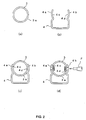
- FIG. 2(a) An electric resistance welded mild steel tube or a drawn tube is cut in a predetermined length to form a cylindrical column jacket 3 comprising a circular outer surface 3a shown in FIG. 2(a).
- a mild steel plate is prepared and press processed into the distance bracket 4 comprising the pair of joint projections 4a and 4b.
- the pair of projections 4a and 4b are symmetrically formed with respect to the center of the distance bracket extending in the same direction.
- Inner surfaces 4c and 4d of the projections 4a and 4b are formed in a circular arc shape conforming to the outer surface 3a of the column jacket 3.
- the distance bracket 4 having the projections 4a and 4b is fitted to the column jacket 3 which was previously processed.
- the inner surfaces 4c and 4d of the projections 4a and 4b are fitted along the outer surface 3a of the column jacket 3.
- they are temporary fixed using a suitable clip so that the position of both members does not change accidentally.
- the arrangement may be such that the distance bracket 4 is temporary fixed to the column jacket 3 by the spring back generated between the projections 4a and 4b.
- the outer surfaces of the projections 4a and 4b of the distance bracket 4 are crimped by applying a punch P.
- these are crimped with the punch P which is pressed toward the center of the column jacket 3 so as not to deform the circular cross-section column jacket 3.
- bracket with the joint projections integral with the main body is fixed by crimping, the number of steps and the number of components are not increased, as is the case of fitting using fasteners, and the manufacturing cost can be kept from increasing.
- the bracket is not jointed by welding, the column jacket is not deformed and the quality can be kept stable.
- welding fumes are not generated, so there can be no generation of greenhouse effect gas such as carbon dioxide.
- the cylindrical column jacket 3 was formed from a mild steel tube.
- the cylindrical column jacket may be formed from an Al-Mn alloy tube instead of a mild steel tube.
- the joint projections are formed on the mild steel distance bracket and the projections are crimped into the Al-Mn alloy column jacket.
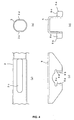
- FIG. 3 An upper bracket 9 for fixing to a body member is mounted on the column jacket 3.
- FIG. 4(a) and (b) While supporting the inner surface by a die (not shown), the opposed outer surfaces are pressed by a punch (not shown) to form a pair of flat surfaces 3c and 3d back to back.
- a mild steel plate is prepared and press processed into the upper bracket 9 comprising a pair of joint projections 9a and 9b.
- the pair of projections 9a and 9b are symmetrically formed as two sets with respect to the center of the upper bracket, so as to protrude outwards.
- Inner surfaces 9c and 9d of the projections 9a and 9b are formed in a flat shape conforming to the flat surfaces 3c and 3d of the column jacket 3.
- the upper bracket 9 having the projections 9a and 9b is fitted to the column jacket 3 which was previously processed.
- the inner surfaces 9c and 9d of the projections 9a and 9b are fitted along the flat surfaces 3c and 3d of the column jacket 3. After assembling, they are temporary fixed using a suitable clip so that the position of both members does not change accidentally.
- the outer surfaces of the projections 9a and 9b of the upper bracket 9 are crimped by applying a punch P. In the present step, these are crimped with the punch P which is pressed toward the center of the column jacket 3 so as not to deform the circular cross-section column jacket 3.
- the positioning during the crimping process is well maintained by the flat surfaces 3c and 3d of the column jacket 3 and the flat inner surfaces 9c and 9d of the projections 9a and 9b of the upper bracket 9, and hence the joint strength can be kept stable.
- cylindrical column jacket 3 was formed from a mild steel tube.
- the cylindrical column jacket may be formed from an Al-Mn alloy tube instead of a mild steel tube.
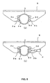
- FIG. 6(a) and (b) a lower bracket 10 for fixing to a body member is mounted on the column jacket 3.
- the lower bracket 10 comprises a pair of joint projections 10a and 10b.
- the pair of joint projections 10a and 10b are formed on the lower bracket 10 in a similar procedure to the method described in the above embodiments. That is, the pair of projections 10a and 10b are symmetrically formed with respect to the center of the lower bracket, so as to extend from the side face.
- Inner surfaces 10c and 10d of the projections 10a and 10b are formed in a circular arc shape conforming to the outer surface 3a of the column jacket 3.
- the lower bracket 10 having the projections 10a and 10b is fitted to the column jacket 3 which was previously processed.
- the inner surfaces 10c and 10d of the projections 10a and 10b are fitted along the outer surface 3a of the column jacket 3. After assembling, they are temporary fixed using a suitable clip so that the position of both members does not change accidentally.
- the outer surfaces of the projections 10a and 10b of the lower bracket 10 are crimped by applying a punch (not shown).
- FIG. 7(a) and (b) a bracket 11 for attaching a combination switch is mounted on the column jacket 3.
- the bracket 11 comprises a pair of joint projections 11a and 11b.
- the pair of projections 11a and 11b are formed on the bracket 11 in a similar procedure to the method described in the above embodiments. That is, the pair of projections 11a and 11b are symmetrically formed with respect to the center of the bracket, so as to protrude from the side face.
- Inner surfaces 11c and 11d of the projections 11a and 11b are formed in a circular arc shape conforming to the outer surface of the column jacket 3.
- the bracket 11 having the projections 11a and 11b is fitted to the column jacket 3 which was previously processed.
- the inner surfaces of the projections 11a and 11b are fitted along the outer surface of the column jacket 3. After assembling, they are temporary fixed using a suitable clip so that the position of both members does not change accidentally.
- the outer surfaces of the projections 11a and 11b of the bracket 11 are crimped by applying a punch (not shown).
- the method according to the present invention of assembling a steering column, is one where when fixing the bracket to the steering column, the bracket is fixed by crimping the joint projections which are integral with the bracket main body, which is effective in not increasing the number of steps and the number of components, and in keeping the manufacturing cost from increasing. Moreover, it is effective in that it is not necessary to strictly control the accuracy of the bracket, so that the bracket can be manufactured at low cost.
Landscapes
- Engineering & Computer Science (AREA)
- Mechanical Engineering (AREA)
- General Engineering & Computer Science (AREA)
- Chemical & Material Sciences (AREA)
- Combustion & Propulsion (AREA)
- Transportation (AREA)
- Steering Controls (AREA)
Applications Claiming Priority (3)
| Application Number | Priority Date | Filing Date | Title |
|---|---|---|---|
| JP2002114121 | 2002-04-17 | ||
| JP2002114121 | 2002-04-17 | ||
| PCT/JP2003/001782 WO2003086835A1 (fr) | 2002-04-17 | 2003-02-19 | Procede de montage de colonnes de direction |
Publications (3)
| Publication Number | Publication Date |
|---|---|
| EP1498340A1 true EP1498340A1 (fr) | 2005-01-19 |
| EP1498340A4 EP1498340A4 (fr) | 2006-04-19 |
| EP1498340B1 EP1498340B1 (fr) | 2009-04-01 |
Family
ID=29243376
Family Applications (1)
| Application Number | Title | Priority Date | Filing Date |
|---|---|---|---|
| EP03746405A Expired - Lifetime EP1498340B1 (fr) | 2002-04-17 | 2003-02-19 | Procede de montage de colonnes de direction |
Country Status (6)
| Country | Link |
|---|---|
| US (1) | US20050223838A1 (fr) |
| EP (1) | EP1498340B1 (fr) |
| JP (1) | JP4214915B2 (fr) |
| AU (1) | AU2003211225A1 (fr) |
| DE (1) | DE60326945D1 (fr) |
| WO (1) | WO2003086835A1 (fr) |
Cited By (1)
| Publication number | Priority date | Publication date | Assignee | Title |
|---|---|---|---|---|
| EP3228522A3 (fr) * | 2016-04-07 | 2018-01-17 | Jtekt Corporation | Appareil de conduite |
Families Citing this family (3)
| Publication number | Priority date | Publication date | Assignee | Title |
|---|---|---|---|---|
| US8220356B2 (en) * | 2008-04-02 | 2012-07-17 | International Truck Intellectual Property Company, Llc | Anti-separation device for use with isolator |
| JP5521321B2 (ja) * | 2008-12-10 | 2014-06-11 | トヨタ自動車株式会社 | ステアリングコラム保持装置 |
| JP5428582B2 (ja) * | 2009-06-30 | 2014-02-26 | 日本精工株式会社 | ステアリング装置 |
Family Cites Families (23)
| Publication number | Priority date | Publication date | Assignee | Title |
|---|---|---|---|---|
| FR2571011B1 (fr) * | 1984-10-01 | 1987-01-09 | Nacam | Dispositif de reglage de colonne de direction pour vehicule automobile |
| US5088768A (en) * | 1989-06-27 | 1992-02-18 | Fuji Kiko Company, Limited | Structure of impact absorbing steering apparatus |
| US5235734A (en) * | 1991-11-04 | 1993-08-17 | Itt Corporation | Collapsible steering shaft apparatus and method of making same |
| US5477750A (en) * | 1993-05-03 | 1995-12-26 | The Torrington Company | Variable length shaft assembly |
| FR2707582B1 (fr) * | 1993-07-16 | 1995-10-20 | Ecia Equip Composants Ind Auto | Corps de colonne de direction pour véhicule automobile. |
| JP3060847B2 (ja) * | 1994-08-30 | 2000-07-10 | トヨタ自動車株式会社 | 車両用ステアリング装置 |
| US5573606A (en) * | 1995-02-16 | 1996-11-12 | Gibbs Die Casting Aluminum Corporation | Aluminum alloy and method for making die cast products |
| DE19506210C1 (de) * | 1995-02-23 | 1996-06-27 | Lemfoerder Metallwaren Ag | Klemmvorrichtung für eine einstellbare Lenksäule in Kraftfahrzeugen |
| JP3317077B2 (ja) * | 1995-03-30 | 2002-08-19 | 日本精工株式会社 | チルト式ステアリング用揺動支持装置 |
| JPH08276852A (ja) | 1995-04-03 | 1996-10-22 | Nippon Seiko Kk | チルト式ステアリング装置 |
| FR2737172B1 (fr) * | 1995-07-26 | 1997-10-10 | Nacam | Systeme de guidage et de verrouillage pour colonne de direction de vehicules automobile |
| DE19629246A1 (de) * | 1996-07-19 | 1998-01-22 | Opel Adam Ag | Vorrichtung zur Verriegelung einer verstellbaren Lenksäule, insbesondere für Kraftfahrzeuge |
| EP0823296A3 (fr) * | 1996-08-03 | 2000-03-01 | Balcke-Dürr GmbH | Procédé de fabrication d'échangeurs de chaleur résistant à la corrosion |
| FR2756535B1 (fr) * | 1996-12-02 | 1999-02-19 | Ecia Equip Composants Ind Auto | Bride de fixation d'un corps de colonne de direction de vehicule automobile sur le reste de la structure de celui-ci |
| JP3791222B2 (ja) * | 1999-01-27 | 2006-06-28 | 日本精工株式会社 | チルト式ステアリング装置 |
| GB9913016D0 (en) * | 1999-06-05 | 1999-08-04 | Delphi Tech Inc | Clamping device for a steering column |
| US6647822B2 (en) * | 2000-02-23 | 2003-11-18 | Freightliner Llc | Vehicle shifter |
| US6629704B2 (en) * | 2001-03-15 | 2003-10-07 | Trw Inc. | Vehicle steering column |
| JP2003118595A (ja) * | 2001-08-06 | 2003-04-23 | Nsk Ltd | 車両用ステアリング装置及びその製造方法 |
| US6908590B2 (en) * | 2002-03-19 | 2005-06-21 | Spx Corporation | Aluminum alloy |
| DE10230284B4 (de) * | 2002-07-05 | 2008-10-16 | Daimler Ag | Verfahren und Vorrichtung zur Befestigung von Bauteilen an umfänglich geschlossensn Hohlprofilen |
| JPWO2004022410A1 (ja) * | 2002-09-04 | 2005-12-22 | 日本精工株式会社 | 車両用位置調整式ステアリングコラム装置 |
| US7325833B2 (en) * | 2002-11-11 | 2008-02-05 | Nsk Ltd. | Steering device for motor vehicle |
-
2003
- 2003-02-19 EP EP03746405A patent/EP1498340B1/fr not_active Expired - Lifetime
- 2003-02-19 AU AU2003211225A patent/AU2003211225A1/en not_active Abandoned
- 2003-02-19 WO PCT/JP2003/001782 patent/WO2003086835A1/fr not_active Ceased
- 2003-02-19 US US10/511,149 patent/US20050223838A1/en not_active Abandoned
- 2003-02-19 DE DE60326945T patent/DE60326945D1/de not_active Expired - Lifetime
- 2003-02-19 JP JP2003583815A patent/JP4214915B2/ja not_active Expired - Fee Related
Cited By (1)
| Publication number | Priority date | Publication date | Assignee | Title |
|---|---|---|---|---|
| EP3228522A3 (fr) * | 2016-04-07 | 2018-01-17 | Jtekt Corporation | Appareil de conduite |
Also Published As
| Publication number | Publication date |
|---|---|
| EP1498340B1 (fr) | 2009-04-01 |
| JP4214915B2 (ja) | 2009-01-28 |
| AU2003211225A1 (en) | 2003-10-27 |
| US20050223838A1 (en) | 2005-10-13 |
| WO2003086835A1 (fr) | 2003-10-23 |
| EP1498340A4 (fr) | 2006-04-19 |
| JPWO2003086835A1 (ja) | 2005-08-18 |
| DE60326945D1 (de) | 2009-05-14 |
Similar Documents
| Publication | Publication Date | Title |
|---|---|---|
| EP1337429B1 (fr) | Structure de joint et procede de fabrication d'une structure de joint | |
| US6188039B1 (en) | Projection welded panel spacer and method for making the same | |
| JP2016161078A (ja) | 異材接合用リベット及び異材接合方法 | |
| US6688000B2 (en) | Joining of tubular parts in a T-joint by riveting/brazing | |
| EP1545824A1 (fr) | Feuilles de metal, tubes, et autres formes similaires faisant l'objet d'un soudage resistant a la deformation | |
| EP1498340A1 (fr) | Procede de montage de colonnes de direction | |
| US20190338798A1 (en) | Component Combination of at Least Two Components and a Method for Producing a Component Combination Joined in a Form-Fitting and/or Force-Fitting Manner | |
| EP1008401A2 (fr) | Procédé de fabrication d'un bras de support | |
| US20040112872A1 (en) | Method for single sided spot welding | |
| JP2004224246A (ja) | サスペンションアーム及びその製造方法 | |
| JP6711253B2 (ja) | 異種部材接合方法 | |
| US7011350B2 (en) | Flash welded joint structure and method for making a joint structure | |
| JP2004338706A (ja) | 自動車のサブフレーム、自動車及び自動車のサブフレームの製造方法 | |
| JP6574884B2 (ja) | 異材接合用リベット、異材接合体、及び異材接合方法 | |
| US20180273095A1 (en) | Vehicle front structure and method for manufacturing same | |
| CN110582650B (zh) | 接合体、汽车用座椅框架以及接合方法 | |
| JP6426043B2 (ja) | 異材接合用リベット、異材接合体、及び異材接合方法 | |
| CN111356609B (zh) | 接合体以及汽车用座椅框架 | |
| JP2005147346A (ja) | 金具固定構造と金具固定方法 | |
| JP2019064133A (ja) | 接合継手、自動車用シートフレーム、および接合継手の製造方法 | |
| JP2014092224A (ja) | ナット付きジョイント部材の製造方法 | |
| WO2018193839A1 (fr) | Corps assemblé, structure de siège pour automobile, et procédé d'assemblage | |
| EP0736401A1 (fr) | Dispositif d'attelage et procédé pour la fabrication d'un dispositif d'attelage | |
| JPH0229895B2 (fr) | ||
| JP4165211B2 (ja) | 自在継手のヨーク |
Legal Events
| Date | Code | Title | Description |
|---|---|---|---|
| PUAI | Public reference made under article 153(3) epc to a published international application that has entered the european phase |
Free format text: ORIGINAL CODE: 0009012 |
|
| 17P | Request for examination filed |
Effective date: 20041111 |
|
| AK | Designated contracting states |
Kind code of ref document: A1 Designated state(s): AT BE BG CH CY CZ DE DK EE ES FI FR GB GR HU IE IT LI LU MC NL PT SE SI SK TR |
|
| AX | Request for extension of the european patent |
Extension state: AL LT LV MK RO |
|
| RIN1 | Information on inventor provided before grant (corrected) |
Inventor name: KOIKE, TETSUYA,C/O NSK LTD. Inventor name: HIGASHINO, KIYOHARUC/O NSK LTD. |
|
| RBV | Designated contracting states (corrected) |
Designated state(s): DE GB |
|
| A4 | Supplementary search report drawn up and despatched |
Effective date: 20060306 |
|
| RIC1 | Information provided on ipc code assigned before grant |
Ipc: B21D 39/04 20060101ALI20060228BHEP Ipc: F16B 17/00 20060101ALI20060228BHEP Ipc: B62D 1/19 20060101ALI20060228BHEP Ipc: B62D 1/16 20060101AFI20031031BHEP Ipc: B62D 1/184 20060101ALI20060228BHEP |
|
| 17Q | First examination report despatched |
Effective date: 20060726 |
|
| GRAP | Despatch of communication of intention to grant a patent |
Free format text: ORIGINAL CODE: EPIDOSNIGR1 |
|
| GRAS | Grant fee paid |
Free format text: ORIGINAL CODE: EPIDOSNIGR3 |
|
| GRAA | (expected) grant |
Free format text: ORIGINAL CODE: 0009210 |
|
| AK | Designated contracting states |
Kind code of ref document: B1 Designated state(s): DE GB |
|
| REG | Reference to a national code |
Ref country code: GB Ref legal event code: FG4D |
|
| REF | Corresponds to: |
Ref document number: 60326945 Country of ref document: DE Date of ref document: 20090514 Kind code of ref document: P |
|
| PLBE | No opposition filed within time limit |
Free format text: ORIGINAL CODE: 0009261 |
|
| STAA | Information on the status of an ep patent application or granted ep patent |
Free format text: STATUS: NO OPPOSITION FILED WITHIN TIME LIMIT |
|
| 26N | No opposition filed |
Effective date: 20100105 |
|
| GBPC | Gb: european patent ceased through non-payment of renewal fee |
Effective date: 20100219 |
|
| PG25 | Lapsed in a contracting state [announced via postgrant information from national office to epo] |
Ref country code: GB Free format text: LAPSE BECAUSE OF NON-PAYMENT OF DUE FEES Effective date: 20100219 |
|
| PGFP | Annual fee paid to national office [announced via postgrant information from national office to epo] |
Ref country code: DE Payment date: 20200204 Year of fee payment: 18 |
|
| REG | Reference to a national code |
Ref country code: DE Ref legal event code: R119 Ref document number: 60326945 Country of ref document: DE |
|
| PG25 | Lapsed in a contracting state [announced via postgrant information from national office to epo] |
Ref country code: DE Free format text: LAPSE BECAUSE OF NON-PAYMENT OF DUE FEES Effective date: 20210901 |