EP1498521A2 - Heald frame and weaving loom fitted with at least one such heald frame - Google Patents
Heald frame and weaving loom fitted with at least one such heald frame Download PDFInfo
- Publication number
- EP1498521A2 EP1498521A2 EP04356131A EP04356131A EP1498521A2 EP 1498521 A2 EP1498521 A2 EP 1498521A2 EP 04356131 A EP04356131 A EP 04356131A EP 04356131 A EP04356131 A EP 04356131A EP 1498521 A2 EP1498521 A2 EP 1498521A2
- Authority
- EP
- European Patent Office
- Prior art keywords
- frame according
- heald frame
- smooth
- fastening
- damping
- Prior art date
- Legal status (The legal status is an assumption and is not a legal conclusion. Google has not performed a legal analysis and makes no representation as to the accuracy of the status listed.)
- Granted
Links
Images


Classifications
-
- D—TEXTILES; PAPER
- D03—WEAVING
- D03C—SHEDDING MECHANISMS; PATTERN CARDS OR CHAINS; PUNCHING OF CARDS; DESIGNING PATTERNS
- D03C9/00—Healds; Heald frames
- D03C9/06—Heald frames
-
- D—TEXTILES; PAPER
- D03—WEAVING
- D03C—SHEDDING MECHANISMS; PATTERN CARDS OR CHAINS; PUNCHING OF CARDS; DESIGNING PATTERNS
- D03C9/00—Healds; Heald frames
- D03C9/06—Heald frames
- D03C9/0608—Construction of frame parts
- D03C9/0616—Horizontal upper or lower rods
- D03C9/0633—Heald bars or their connection to other frame parts
-
- D—TEXTILES; PAPER
- D03—WEAVING
- D03C—SHEDDING MECHANISMS; PATTERN CARDS OR CHAINS; PUNCHING OF CARDS; DESIGNING PATTERNS
- D03C9/00—Healds; Heald frames
- D03C9/02—Healds
-
- D—TEXTILES; PAPER
- D03—WEAVING
- D03C—SHEDDING MECHANISMS; PATTERN CARDS OR CHAINS; PUNCHING OF CARDS; DESIGNING PATTERNS
- D03C9/00—Healds; Heald frames
- D03C9/06—Heald frames
- D03C9/0691—Arrangements of means for damping or noise reduction
Definitions
- the present invention relates to a heald frame, and a loom equipped with at least one such frame.
- Such a heald frame first comprises a body, which is formed by reversible assembly of two uprights and two sleepers. In use, the amounts are substantially vertical, while the sleepers are substantially horizontal.
- Each cross supports also an attachment member, also called bar, which allows the attachment of a corresponding end of smooth of the loom.
- the invention aims more particularly at such a framework of smooth which is provided with damping means, interposed between the fastener and the rails, at the level of least one end of these.
- US-A-3,895,655 discloses a heald frame, which is provided with such vibration damping elements. These resilient elements, which are fixed on each cross, are interposed between the faces opposite these sleepers and smooth, so as to act on the ends of these latest.
- the invention proposes to carry out a frame of smooths to remedy the different disadvantages of the prior art mentioned above.
- a frame of loom comprising two uprights and two sleepers, each crossing being provided with an organ attachment adapted to receive a corresponding end at least one rail of said frame, while it is also provided damping means, integral with at least one corresponding fastening member, this at least one member fastening being formed of at least one folded sheet.
- the invention also relates to a loom equipped with at least one heald frame as defined above.
- a dobby 1 of a type known per se, is intended to lead to a heald frame 2 belonging to a loom M, according to an oscillating vertical movement represented by the arrows F 1 and F ' 1 .
- an actuating arm la of the dobby is coupled to each smooth frame 2, by means of rods and oscillating levers.
- the trade M comprises several frames, generally between six and twenty-four, of which only one is shown in FIG. 1 for the sake of clarity.
- Each frame 2 comprises a body, which is formed by the assembly of two uprights 4, 4 'and two crosspieces 6, 6 '.
- Each upper respectively 6 and 6 6 ' is equipped, in known manner, with an organ corresponding snap, or bar 8, 8 '.
- These strips 8 and 8 ' which will be described in more detail in the following, allow the fixation of the ends respectively upper and lower of different 10, belonging to the frame 2 of the loom M.
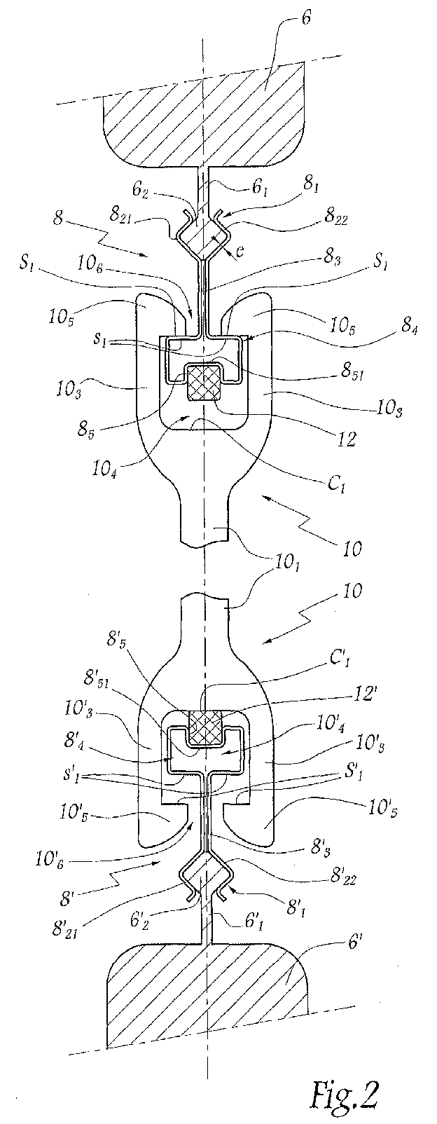
- Figure 2 illustrates the attachment of the end upper part of a rail 10 on the upper cross member 6, of the bar 8. It should be noted that the fixation of the lower end of this rail 10 on the crossbar 6 ' is done in a similar way, by means of the bar 8 '. With this in mind, the mechanical elements of the transom 6 ', of the lower bar 8' and of the lower end of the smooth 10, analogues respectively to those of the upper crossbar 6, the upper bar 8 and the upper end of the smooth 10, carry the same numbers assigned the reference "premium".
- the structure of the upper cross member 6, which is conventional, will not be described in more detail in the following.
- the underside of this crosspiece 6, facing the smooth 10, is extended by a rib 6 1 extending over the entire main dimension of this cross.
- This rib 6 1 is extended by a lug 6 2 having, in cross section, substantially a diamond shape.
- the fastening strip 8 is formed by a folded thin sheet whose thickness e is for example close to 0.7 mm. It comprises first a region 8 1 , for fixing the bar 8 on the cross member 6, by cooperation of forms.
- this fixing region is formed of two branches 8 21 and 8 22 , generally having a shape of L, the corners of which are placed opposite each other, so as to cover the aforementioned ergot 6 2 . It should also be noted that these branches 8 21 , 8 22 constitute the free ends of the folded sheet, forming the fastening bar 8.
- this lug 6 2 associated with the branches 8 21 and 8 22 , thus gives a removable character to the fixing of the bar 8 on the crossbar 6.
- the folded sheet constitutive of the bar 8 is elastic and / or prestressing.
- the two branches 8 21 and 8 22 meet, opposite the crossbar 6, an intermediate region 8 3 , of reduced cross section. It finally extended by a Region 8 4 for the attachment of the rail 10, which will be described in more detail in the following.
- This smooth 10 comprises, in a conventional manner, a filamentary element 10 1 , provided with an eyelet 10 2 , visible in Figure 1, for the passage of a not shown chain wire.
- the filiform element 10 1 extends into two main branches 3 , defining a housing 4 to receive the bar 8.
- the outlet of this housing is bordered by two teeth 5 of the rail, extending towards each other, so as to form a neck 10 6 of restricted transverse dimension.
- attachment region 8 4 has a roughly rectangular cross section, whose dimensions are significantly greater than those of the intermediate region 8 3 .
- This attachment region 8 4 forms, in its lower part opposite the crosspiece 6, a U-shaped fold 8 5 , whose core 8 51 is turned towards the cross member 6.
- This fold ensures the retention of a damping element 12, of known type, which is a flexible element made for example of a polymer material, an elastomeric material, or the like.
- a damping element which extends over substantially the entire major dimension of the cross member 6 is retained by wedging and / or bonding in the interior of the fold 8 5 in the form of U.
- the intermediate region 8 3 is received in the neck 10 6 , while the attachment region 8 4 is received in the housing 10 4 .
- the various mechanical elements being arranged symmetrically with respect to the median horizontal axis of the frame 2.
- s 1 the surfaces of the upper latching bar 8, which are adapted to come into direct abutment against the surfaces Si facing the smooth, belonging to the two teeth 10 5 .
- These direct bearing surfaces s 1 and S 1 form a traction zone, opposite to the compression zone, corresponding to the free surfaces of the damping element 12 and to those C 1 opposite the arm 10.
- Providing substantially simultaneous support on traction surfaces, lower or upper, and on compression surfaces, upper or lower, allows to work the sleepers 6 and 6 'in a configuration where the rails are substantially straight. This is favorable to the transmission of an effort of maximum compression.
- One of the two sleepers which ensures a buffer role, so absorbs a significant effort and reduces the bending of the other crossbar, ensuring then a pulling force.
- damping means 12 and 12 ' equip the bars 8 and 8 respectively. However, it can be provided to provide only one of these bars 8 or 8 'such damping means, while the other 8' or 8 is devoid of. In this case, when the single damping means 12 or 12 ', integral with the bar 8 or 8' are in contact with the compression surfaces of the end facing the bar, the other end thereof is advantageously in contact, by its traction surfaces S ' 1 or S 1 , with the other facing bar 8' or 8.
- FIG 3 illustrates a first variant of embodiment of the invention.
- the elements similar to those in Figure 2 are affected the same reference numbers, increased by 100.
- the crosspiece 106 is hollowed out with a recess 106 1 having, in cross-section, a diamond shape.
- This recess which is open towards the not shown smooth, opens outward via a neck of reduced transverse dimension.
- the bar 108 is provided with a fixing region 108 1 , which comprises two L-shaped legs 108 21 and 108 22 , forming the free ends of the folded sheet constituting the bar 108.
- the attachment region 108 1 can be introduced into the recess 106 1 , by pinching the two branches 108 21 and 108 22 , so that it penetrates through the aforementioned neck. Then, these two branches are pressed against the walls 106 2 of the recess 106 1 , by elasticity and / or prestressing of the constituent plate of the bar.
- the two branches 108 21 , 108 22 come together in an intermediate region 108 3 , of reduced section, which extends into an attachment region 108 4 .
- the latter has a generally similar profile to that of region 8 4 of Figure 2, except the fold 108 5 which has a U-shaped section with wings oppositely inclined from one another. In other words, this fold 108 5 defines a housing which has larger dimensions at the core 108 51 of the U at its outlet.
- the bar 108 is finally provided with a damping element 112, having an overall mushroom shape. It thus comprises a foot 112 1 , received in the interior volume of the fold 108 5 , and a head 112 2 bearing against the underside of the bar 108.
- the mutual connection between the bar 108 and the damping element 112 is realized thanks to a jamming by cooperation of forms and / or a collage.
- FIG 4 illustrates a second variant of embodiment of the invention.
- the elements similar to those in Figure 2 are affected the same reference numbers, increased by 200.
- the hooking region 208 4 of the bar 208 has roughly a form of rectangle. It is provided with two lower branches 208 41 , which are inclined opposite the crosspiece 206.
- Each branch 208 41 is extended by a corresponding fold 208 5 , having substantially a V shape. These two folds 208 5 are connected by a terminal link section 208 6 , roughly in the shape of a circular arc.
- damping element 212 is hollowed out, so that the walls of this recess are pressed against the outer face of the branches 208 41 , folds 208 5 and connecting section 208 6 .
- This element 212 which is therefore particularly retained at the two folds 208 5 , is fixed to the bar 208 by cooperation of shapes and / or bonding.
- the damping element 212 has lateral dimensions greater than those of the hooking region 208 4 .
- this damping element is provided with two lateral projections 212 1 , delimiting two functional sets denoted J. In service, these projections therefore extend in the vicinity of the branches 210 3 of the rail 210, so as to avoid any contact between these branches and the attachment region 208 4 of the bar 208.
- the attachment region 208 4 extends, opposite the damping element 212, by an intermediate region 208 3 , similar to those 8 3 and 108 3 described above. Unlike the previous examples, the region 208 1 for attachment to the cross member 206 is formed by a simple extension of the intermediate region 208 3 , without changing the transverse dimensions with respect to the latter.
- the two branches 208 21 and 208 22 are thus fixed permanently on the upper cross member 206, in particular by gluing or by wedging.
- FIG. 5 illustrates a third variant of embodiment of the invention.
- the elements similar to those in Figure 2 are affected the same reference numbers, increased by 300.
- the bar 308 of FIG. 5 differs from those of previous examples, in that it is formed of two plates folded apart 309 and 309 '. These latter extend, in service, in a mutually symmetrical manner with respect to Z-Z 'direction of vertical oscillation of the frames.
- the attachment region 308 4 therefore differs from those of the previous examples in that it is open opposite the cross member 306. More specifically, this attachment region 308 4 has a generally U-shape, whose wings 308 41 and 308 '41 are terminated by recessed flanges 308 5 and 308' 5 , each of which belongs to a corresponding folded sheet 309 or 309 '. These reentrant edges thus form folds of the constituent plates of the bar 308, while the damping element 312, which is generally solid, is hollowed out with two notches 312 1 and 312 ' 1 , intended to receive these edges 308. 5 and 308 ' 5 .
- the hooking region 308 4 extends into an intermediate region 308 3 , which is itself terminated by a region 308 1 , ensuring the attachment of the bar 308 to the cross member 6. More precisely, these regions respectively intermediate 308 3 and fixing 308 1 are constituted by two parallel branches 308 21 and 308 22 , each of which belongs to a corresponding folded sheet 309 or 309 '.
- FIG 6 illustrates a fourth variant of embodiment of the invention.
- the elements similar to those in Figure 2 are affected the same reference numbers, increased by 400.
- Smooth 410 of this embodiment differs from the previous examples in that it is asymmetrical. Each of its ends thus has an overall shape of C, the filiform element 410 1 being extended by a single branch 410 3 , from which respectively an intermediate tooth 410 31 and a return 410 32 extend. This tooth and this return, which are directed toward one another, define, with the branch 410 3 , two gaps 410 41 , 410 42 .
- the bar 408 comprises a zone 408 5 , folded U-shaped, in which is housed the damping element 412, which is fixed by cooperation of shapes and / or bonding.
- This damping element 412 is provided with a rib 412 1 , extending towards the filiform element 410 1 , which is received in the gap 410 41 .
- One 408 52 of the wings of the U-shaped portion 408 5 is extended by an intermediate branch 408 4 , extending along the vertical axis ZZ 'into the interstice 410 42 , so as to ensure the hooking
- This intermediate branch is extended by an end branch 408 2 , generally L-shaped.
- this end branch 408 2 comprises a section 408 41 , parallel to the intermediate branch 408 4 , as well as a terminal section 408 22 , forming a free end of the folded sheet constituting the bar 408.
- section 408 41 is separated from the walls facing the return 410 32 of the arm 410, which delimits a functional lateral play, noted j, to substantially prevent contact between these two mechanical elements.
- the terminal section 408 22 and the wing 408 52 which are generally parallel, are bent so as to have a local increase in their relative spacing. This therefore allows the fixing of the bar 408 on a lug 406 2 of the cross 406 having, in cross section, substantially a diamond shape. This mutual fixation is ensured in a manner analogous to that described with reference to the first embodiment, illustrated in FIG. 2.
- the surfaces of the latching bar 408, which are adapted to bear directly against the surfaces S 2 opposite the smooth 410 C 2 also denotes the surfaces of the beam against which the damping element 412 is able to abut by its rib 412 1 .
- the cushioning member 412 is provided opposite surfaces s2 direct support of the catching bar 408.
- FIG 7 illustrates a fifth variant of embodiment of the invention.
- the elements similar to those in Figure 2 are affected the same reference numbers, increased by 500.
- Smooth 510 of this FIG. 7 differs from that of FIG. 6 in that it has an overall section in the form of J. Thus, it is only provided with an upper return 510 32 , being devoid of a lower tooth.
- the branch 510 3 of the bar 510 is distant from the facing leg 508 4 of the bar 508, thus forming a first lateral functional game, noted J '.
- One 508 52 of the wings of the portion 508 5 U-shaped is extended by the aforementioned branch 508 4 , which is partially received in the gap 510 42 , so as to ensure the attachment of the smooth 510.
- This branch 508 4 is terminated by a return 508 41 , extending substantially 180 °, which is placed at a distance from the upper return 510 32 facing, belonging to the smooth 510, so as to form a second lateral functional game, noted j ' .
- the other 508 53 of the wings of the portion 508 5 forms a free end of the bar 508. This wing 508 53 enters a notch formed in the damping element 512.
- damping element 512 does not necessarily extend against the core 508 51 and the wing 508 52 of the portion 508 5 .
- this damping element 512 is provided with a part 512 1 , projecting laterally with respect to the arm 508 4 of the bar 508. In service, this projection 512 1 therefore bears against the branch 510 3 of the rail 510, so as to avoid any contact between this branch of the rail and the arm 508 4 opposite the bar 508.
- each of the strips 408 or 508 FIGS. 6 and 7 are indifferently suitable for use with smooth of different shapes, especially in C or J. Thus, there is only place for change the damping element 412 or 512, depending on the considered use.
- Figure 8 illustrates a sixth variant of embodiment of the invention.
- Smooth 610 of this figure 8 is similar to that 410 of Figure 6.
- this smooth 610 comprises a filiform body 610 1 extended by a main branch 610 3 , from which respectively extend an intermediate tooth 610 31 and a return 610 32 .
- This tooth and this return define, with the aforementioned main branch, two interstices 610 41 and 610 42 , while we note E the free end of this smooth 610.
- the bar 608 comprises a fixing branch 608 6 , which is permanently fixed on the cross member 606, in particular by gluing.
- This branch 608 6 is extended upwards, namely opposite the filiform body 610 1 , by a fold 608 5 , generally having a shape of U.
- this fold 608 5 ensures the retention of a damping element 612, by wedging and / or gluing.
- the securing branch 608 6 is further extended, opposite the fold 608 5 , by a first hooking branch 608 4 , which is received in the gap 610 42 .
- This branch 608 4 is extended by a first return 608 41 , parallel to the main branch 610 3 .
- This first return is itself extended by a second hooking branch 608 ' 4 , received in the gap 610 41 , which is terminated by a second return 608' 41 , directed towards the free end E of the bar.
- the damping member 612 is not placed opposite the direct bearing surfaces of the fastener against the bar. Indeed, in this figure 8, this attachment member 612 is placed opposite the free end E of the smooth 610, with respect to the filiform body 610 1 thereof.
- Figure 9 illustrates a seventh variant of embodiment of the invention.
- the smooth 710 of this FIG. 9, which is similar to that of FIG. 2, comprises a filiform body 710 1 , which extends into two main branches 710 3 , defining a housing 710 4 for receiving the bar 708.
- the outlet this housing is bordered by two teeth 710 5 of the smooth, which define a neck 710 6 of reduced transverse dimension.
- E ' the free end of this smooth, opposite the filiform body 710 1 .
- the bar 708, which is generally similar to that 8 of Figure 2, comprises an attachment region formed by two branches 708 21 and 708 22 , adapted to cap a lug 706 2 of the bar 706. At the opposite of this region the bar 708 is equipped with an attachment region 708 4 , which has a roughly rectangular cross section.
- this attachment region 708 4 is received in the housing 710 4 of the rail 710.
- this attachment region is devoid of a fold, intended to to the retention of a damping member.
- the attachment region and the attachment region are mutually connected by an intermediate region 708 3 , a portion of which is received in the neck 710 6 .
- this intermediate region does not have a constant cross section.
- two lateral projections 708 31 generally U-shaped, which extend symmetrically with respect to the main vertical axis of the bar. These two projections 708 31 define, opposite the free end E ', two folds 708 5 V-shaped, for the holding by cooperation of shapes and / or bonding two damping members 712.
- each damping member 712 is placed opposite the free end E 'of the heald 710, with respect to the filiform body 710 1 thereof .
- this free end E ' is able to bear against each of these damping members.
- a single projection 708 31 associated with a single damper 712.
- at least one damper may be fixed directly, for example by gluing, on a vertical part of the intermediate region 708 3 , which is then devoid of lateral projection.
- the invention makes it possible to achieve the objectives previously mentioned.
- the reduced section of the constituent plate of the snap bar makes it less sensitive to the problems of differential dilation, which are the shackles proposed in the art prior.
Landscapes
- Engineering & Computer Science (AREA)
- Textile Engineering (AREA)
- Looms (AREA)
- Vibration Prevention Devices (AREA)
Abstract
Ce cadre comprend deux montants et deux traverses (6), dont chacune est pourvue d'un organe d'accrochage (8) apte à recevoir une extrémité correspondante d'au moins une lisse (10), alors qu'il est prévu des moyens d'amortissement (12) solidaires d'au moins un organe d'accrochage correspondant, qui sont placés à l'opposé de surfaces (s1) d'appui direct de cet organe d'accrochage contre une lisse correspondante.This frame comprises two uprights and two crosspieces (6), each of which is provided with a fastening member (8) adapted to receive a corresponding end of at least one stringer (10), while means are provided damping means (12) integral with at least one corresponding fastening member, which are placed opposite surfaces (s 1 ) of direct support of this fastening member against a corresponding rail.
Le ou chaque organe d'accrochage (8) est formé d'au
moins une tôle repliée, qui assure la fixation des moyens
d'amortissement (12) par coopération de formes et/ou par
collage.
Description
La présente invention concerne un cadre de lisses, ainsi qu'un métier à tisser équipé d'au moins un tel cadre.The present invention relates to a heald frame, and a loom equipped with at least one such frame.
Il est connu d'équiper un métier à tisser au moyen de cadres de lisses, qui sont destinés à être commandés dans un mouvement d'oscillations verticales grâce à un dispositif approprié, tel qu'une mécanique d'armure ou une ratière.It is known to equip a loom by means of smooth frames, which are intended to be ordered in a movement of vertical oscillations thanks to a appropriate device, such as armor mechanics or dobby.
Un tel cadre de lisses comprend tout d'abord un corps, qui est formé par assemblage réversible de deux montants et de deux traverses. En service, les montants sont sensiblement verticaux, alors que les traverses sont sensiblement horizontales. Chaque traverse supporte également un organe d'accrochage, encore dénommé barrette, qui permet la fixation d'une extrémité correspondante des lisses du métier à tisser.Such a heald frame first comprises a body, which is formed by reversible assembly of two uprights and two sleepers. In use, the amounts are substantially vertical, while the sleepers are substantially horizontal. Each cross supports also an attachment member, also called bar, which allows the attachment of a corresponding end of smooth of the loom.
L'invention vise plus particulièrement un tel cadre de lisses qui est pourvu de moyens d'amortissement, interposés entre l'organe d'accrochage et les lisses, au niveau d'au moins une extrémité de celles-ci. Ainsi, lors des oscillations du cadre, certains contacts directs entre l'organe d'accrochage et les lisses sont supprimés, ce qui réduit les vibrations par rebondissement des lisses sur les barrettes et, par là, l'usure globale subie par ces différents éléments mécaniques tout en augmentant la durée d'utilisation.The invention aims more particularly at such a framework of smooth which is provided with damping means, interposed between the fastener and the rails, at the level of least one end of these. Thus, during oscillations of the frame, certain direct contacts between the shackle and the rails are removed, which reduces vibration by bouncing smooth on bars and, hence, the global wear suffered by these different mechanical elements while increasing the duration use.
US-A-3,895,655 décrit un cadre de lisses, qui est pourvu de tels éléments d'amortissement des vibrations. Ces éléments résilients, qui sont fixés sur chaque traverse, sont interposés entre les faces en regard de ces traverses et des lisses, de façon à agir sur les extrémités de ces dernières.US-A-3,895,655 discloses a heald frame, which is provided with such vibration damping elements. These resilient elements, which are fixed on each cross, are interposed between the faces opposite these sleepers and smooth, so as to act on the ends of these latest.
Cette solution connue présente cependant certains inconvénients, en ce sens qu'il est difficile de maítriser la distance séparant ces éléments amortissants et l'organe d'accrochage. Par ailleurs, l'opération de fixation de ces éléments résilients s'avère coûteuse, alors que leur présence confère une masse additionnelle importante à l'ensemble du cadre.This known solution, however, presents some disadvantages, in that it is difficult to control the distance separating these damping elements and the organ hooking. Moreover, the operation of fixing these resilient elements is costly, whereas their presence confers an important additional mass to the entire frame.
Il est également connu, par US-A-4,106,529 et US-A-4,106,530, d'insérer des éléments amortissants résilients entre les lisses et les organes d'accrochage. Ces éléments amortissants, qui sont prévus d'un côté ou des deux côtés des organes d'accrochage, peuvent être disposés de façon libre, ou bien être fixés dans des rainures ménagées sur les organes d'accrochage.It is also known from US-A-4,106,529 and US-A-4,106,530, to insert resilient damping elements between the rails and the shackles. These elements dampers, which are provided on one or both sides shackles, can be arranged so free, or be fixed in grooves on the shackles.
Cette solution alternative implique cependant d'autres inconvénients.This alternative solution, however, involves other disadvantages.
En effet, si les éléments amortissants sont montés de façon libre, leur positionnement ne se révèle pas satisfaisant. En revanche, s'ils sont reçus dans des rainures, la réalisation de l'organe d'accrochage s'en trouve difficile et coûteuse, puisque les rainures précitées présentent des dimensions très faibles et sont délicates à usiner. Par ailleurs, une telle solution contribue à alourdir notablement l'ensemble de l'organe d'accrochage.Indeed, if the damping elements are mounted free way, their positioning is not revealed satisfactory. On the other hand, if they are received in grooves, the realization of the fastening member find it difficult and expensive, since the grooves mentioned above have very small dimensions and are delicate to machine. Moreover, such a solution contributes to significantly weigh down the whole organ hooking.
Ceci étant précisé, l'invention se propose de réaliser un cadre de lisses permettant de remédier aux différents inconvénients de l'art antérieur évoqués ci-dessus.That being said, the invention proposes to carry out a frame of smooths to remedy the different disadvantages of the prior art mentioned above.
Elle se propose notamment de réaliser un tel cadre qui, tout en étant pourvu de moyens d'amortissement positionnés de façon précise, conserve une masse acceptable ainsi qu'un coût de fabrication réduit.In particular, it proposes to create such a framework which, while being provided with damping means accurately positioned, maintains an acceptable mass as well as a reduced manufacturing cost.
A cet effet, elle a pour objet un cadre de lisses pour métier à tisser, ledit cadre comprenant deux montants et deux traverses, chaque traverse étant pourvue d'un organe d'accrochage apte à recevoir une extrémité correspondante d'au moins une lisse dudit cadre, alors qu'il est également prévu des moyens d'amortissement, solidaires d'au moins un organe d'accrochage correspondant, cet au moins un organe d'accrochage étant formé d'au moins une tôle repliée.For this purpose, it relates to a frame of loom, said frame comprising two uprights and two sleepers, each crossing being provided with an organ attachment adapted to receive a corresponding end at least one rail of said frame, while it is also provided damping means, integral with at least one corresponding fastening member, this at least one member fastening being formed of at least one folded sheet.
L'invention a également pour objet un métier à tisser équipé d'au moins un cadre de lisses tel que défini ci-dessus.The invention also relates to a loom equipped with at least one heald frame as defined above.
L'invention sera mieux comprise et d'autres avantages apparaítront plus clairement à la lumière de la description qui va suivre d'un métier à tisser et de plusieurs cadres de lisses conformes à son principe, donnée uniquement à titre d'exemples non limitatifs et faite en référence aux dessins annexés, dans lesquels :
- la figure 1 est une représentation schématique de principe d'un métier à tisser conforme à l'invention ;
- la figure 2 est une vue en coupe transversale, selon la ligne II-II à la figure 1, illustrant de façon partielle un cadre de lisses appartenant au métier à tisser de la figure 1, en particulier en ce qui concerne la solidarisation mutuelle d'une traverse, d'un organe d'accrochage et d'une lisse appartenant à ce cadre ; et
- les figures 3 à 9 sont des vues en coupe transversale, analogues à cette figure 2, illustrant sept variantes de réalisation de l'invention.
- Figure 1 is a schematic representation of a weaving machine according to the invention;
- FIG. 2 is a cross-sectional view, along the line II-II in FIG. 1, partially illustrating a heald frame belonging to the loom of FIG. 1, in particular with regard to mutual bonding of FIG. a cross member, a fastening member and a rail belonging to this frame; and
- Figures 3 to 9 are cross-sectional views, similar to Figure 2, illustrating seven embodiments of the invention.
A la figure 1, une ratière 1, de type connu en soi,
est destinée à entraíner un cadre de lisses 2 appartenant à
un métier à tisser M, selon un mouvement vertical oscillant
matérialisé par les flèches F1 et F'1. A cet effet, un bras
d'actionnement la de la ratière est attelé à chaque cadre
de lisses 2, au moyen de bielles et de leviers oscillants.
Le métier M comporte plusieurs cadres, généralement entre
six et vingt-quatre, dont un seul est représenté sur la
figure 1 dans un but de clarté. In FIG. 1, a
Chaque cadre 2 comprend un corps, qui est formé par
l'assemblage de deux montants 4, 4' et de deux traverses 6,
6'. Les montants 4, 4' s'étendent globalement selon une
direction parallèle à celle Z-Z' d'oscillation verticale
des cadres, à savoir verticalement en service. Par
ailleurs, les traverses 6, 6' s'étendent selon une
direction Y-Y', qui est perpendiculaire à celle Z-Z'
précitée, à savoir horizontalement en service.Each
Chaque traverse respectivement supérieure 6 et
inférieure 6' est équipée, de façon connue, d'un organe
d'accrochage correspondant, ou barrette 8, 8'. Ces
barrettes 8 et 8', qui seront décrites plus en détail dans
ce qui suit, permettent la fixation des extrémités
respectivement supérieure et inférieure de différentes
lisses 10, appartenant au cadre 2 du métier à tisser M.Each upper respectively 6 and 6
6 'is equipped, in known manner, with an organ
corresponding snap, or
La figure 2 illustre la fixation de l'extrémité
supérieure d'une lisse 10 sur la traverse supérieure 6, au
moyen de la barrette 8. Il est à noter que la fixation de
l'extrémité inférieure de cette lisse 10 sur la traverse 6'
est réalisée de manière analogue, au moyen de la barrette
8'. Dans cet esprit, les éléments mécaniques de la traverse
inférieure 6', de la barrette inférieure 8' et de
l'extrémité inférieure de la lisse 10, analogues
respectivement à ceux de la traverse supérieure 6, de la
barrette supérieure 8 et de l'extrémité supérieure de la
lisse 10, portent les mêmes numéros affectés de la
référence « prime ».Figure 2 illustrates the attachment of the end
upper part of a
La structure de la traverse supérieure 6, qui est
classique, ne sera pas décrite plus en détail dans ce qui
suit. La face inférieure de cette traverse 6, tournée vers
la lisse 10, est prolongée par une nervure 61 s'étendant sur
toute la dimension principale de cette traverse. Cette
nervure 61 est prolongée par un ergot 62 présentant, en
coupe transversale, sensiblement une forme de losange. The structure of the
La barrette d'accrochage 8 est formée par une tôle
mince repliée, dont l'épaisseur e est par exemple voisine
de 0,7 mm. Elle comporte tout d'abord une région 81,
permettant la fixation de la barrette 8 sur la traverse 6,
par coopération de formes.The
De façon plus précise, cette région de fixation est
formée de deux branches 821 et 822, présentant globalement
une forme de L, dont les angles sont placés à l'opposé l'un
de l'autre, de façon à coiffer l'ergot précité 62. Il est
également à noter que ces branches 821, 822 constituent les
extrémités libres de la tôle repliée, formant la barrette
d'accrochage 8.More precisely, this fixing region is formed of two
L'existence de cet ergot 62, associé aux branches 821
et 822, confère ainsi un caractère amovible à la fixation de
la barrette 8 sur la traverse 6.The existence of this
A cet égard, on notera que, de façon avantageuse, la
tôle repliée constitutive de la barrette 8 est élastique
et/ou précontrainte.In this respect, it should be noted that, advantageously, the
folded sheet constitutive of the
Les deux branches 821 et 822 se rejoignent, à l'opposé
de la traverse 6, en une région intermédiaire 83, de section
transversale réduite. Celle-ci se prolonge enfin par une
région 84, destinée à l'accrochage de la lisse 10, qui sera
décrite plus en détail dans ce qui suit.The two
Cette lisse 10 comprend, de façon classique, un
élément filiforme 101, pourvu d'un oeillet 102, visible sur
la figure 1, destiné au passage d'un fil de chaíne non
représenté. A chaque extrémité de la lisse, l'élément
filiforme 101 se prolonge en deux branches principales 103,
définissant un logement 104 de réception de la barrette 8.
Le débouché de ce logement est bordé par deux dents 105 de
la lisse, s'étendant l'une vers l'autre, de façon à former
un col 106 de dimension transversale restreinte.This smooth 10 comprises, in a conventional manner, a
En revenant à la région d'accrochage 84, cette dernière
présente une section transversale à peu près rectangulaire,
dont les dimensions sont nettement supérieures à celles de
la région intermédiaire 83. Cette région d'accrochage 84
forme, dans sa partie inférieure opposée à la traverse 6,
un repli 85 en forme de U, dont l'âme 851 est tournée vers
la traverse 6.Returning to the
Ce repli assure la retenue d'un élément
d'amortissement 12, de type connu en soi, qui est un
élément souple par exemple réalisé en un matériau polymère,
en un matériau élastomère, ou analogue. Un tel élément
amortissant, qui s'étend sur sensiblement l'intégralité de
la dimension principale de la traverse 6, se trouve retenu
par coincement et/ou collage dans le volume intérieur du
repli 85 en forme de U.This fold ensures the retention of a
En configuration d'utilisation du métier à tisser M,
la région intermédiaire 83 est reçue dans le col 106, alors
que la région d'accrochage 84 est reçue dans le logement
104. Il en va de même pour ce qui est de l'extrémité
inférieure de la traverse, les différents éléments
mécaniques étant agencés de façon symétrique par rapport à
l'axe horizontal médian du cadre 2.In the configuration of use of the loom M, the
De manière plus précise, on note s 1 les surfaces de la
barrette supérieure d'accrochage 8, qui sont propres à
venir en appui direct contre les surfaces Si en regard de la
lisse, appartenant aux deux dents 105. Ces surfaces d'appui
direct s 1 et S1 forment une zone de traction, opposée à la
zone de compression, correspondant aux surfaces libres de
l'élément d'amortissement 12 et à celles C1 en regard de la
lisse 10.More specifically, we note s 1 the surfaces of the
A l'état statique, comme illustré à la figure 2,
lorsque l'extrémité supérieure de la lisse se trouve en
appui direct contre les surfaces supérieure s 1 en regard de
la barrette 8, l'extrémité inférieure de cette lisse se
trouve sensiblement en appui contre l'élément
d'amortissement inférieur 12', au niveau de ses surfaces
inférieures de compression C'1. Bien évidemment, lorsque
l'extrémité inférieure de la lisse se trouve en appui
direct, par ses surfaces de traction S'1, sur les surfaces
s'1 de la barrette inférieure 8', la partie supérieure de
cette lisse se trouve sensiblement en appui, par ses
surfaces supérieures de compression C1, contre l'élément
supérieur d'amortissement 12.In the static state, as shown in Figure 2, when the top of the boom end is in direct abutment against the upper surfaces s 1 next to the
Une telle mesure est avantageuse. En effet, les traverses respectivement supérieure 6 et inférieure 6' sont soumises en service à des vibrations, ce qui confère un caractère variable à leur écartement. Les lisses viennent en contact, respectivement avec la barrette et avec l'élément d'amortissement, tantôt par leurs surfaces de traction et tantôt par leurs surfaces de compression, les chocs sur les surfaces de compression contribuant à amortir les vibrations.Such a measure is advantageous. Indeed, respectively upper 6 and lower 6 'are subjected to vibration, which gives a high degree of variable character at their spacing. The smooth ones come in contact, respectively with the bar and with the damping element, sometimes by their surfaces of traction and sometimes by their compression surfaces, the shocks on compression surfaces helping to cushion the vibrations.
Le fait de prévoir un appui sensiblement simultané sur
les surfaces de traction, inférieure ou supérieure, et sur
les surfaces de compression, supérieure ou inférieure,
permet de faire travailler les traverses 6 et 6' dans une
configuration où les lisses sont sensiblement rectilignes.
Ceci est favorable à la transmission d'un effort de
compression maximal. L'une des deux traverses, qui assure
un rôle d'amortisseur, absorbe donc un effort important et
permet de réduire la flexion de l'autre traverse, assurant
alors un effort de traction.Providing substantially simultaneous support on
traction surfaces, lower or upper, and on
compression surfaces, upper or lower,
allows to work the
Ainsi, lors des oscillations du cadre 2, la présence
des éléments d'amortissement respectivement supérieur 12 et
inférieur 12' permet de réduire les oscillations vibrations
axiales des lisses et leurs chocs sur les barrettes. Ceci
assure donc une réduction de l'usure globale subie par ces
lisses et ces barrettes et, par conséquent, d'en augmenter
la durée d'utilisation. Thus, during oscillations of the
A la figure 2, des moyens d'amortissement 12 et 12'
équipent les barrettes respectivement supérieure 8 et
inférieure 8'. Cependant, on peut prévoir de munir
uniquement l'une de ces barrettes 8 ou 8' de tels moyens
d'amortissement, alors que l'autre 8' ou 8 en est
dépourvue. Dans ce cas, lorsque les uniques moyens
d'amortissement 12 ou 12', solidaires de la barrette 8 ou
8' sont en contact avec les surfaces de compression de
l'extrémité en regard de la lisse, l'autre extrémité de
celle-ci est avantageusement en contact, par ses surfaces
de traction S'1 ou S1, avec l'autre barrette d'accrochage en
regard 8' ou 8.In FIG. 2, damping means 12 and 12 'equip the
La figure 3 illustre une première variante de réalisation de l'invention. Sur cette figure, les éléments mécaniques analogues à ceux de la figure 2 y sont affectés des mêmes numéros de référence, augmentés de 100.Figure 3 illustrates a first variant of embodiment of the invention. In this figure, the elements similar to those in Figure 2 are affected the same reference numbers, increased by 100.
La traverse 106 est creusée d'un évidement 1061
présentant, en coupe transversale, une forme de losange.
Cet évidement, qui est ouvert en direction de la lisse non
représentée, débouche vers l'extérieur via un col, de
dimension transversale réduite.The
La barrette 108 est pourvue d'une région de fixation
1081, qui comporte deux branches 10821 et 10822 en forme de
L, formant les extrémités libres de la tôle repliée
constitutive de la barrette 108.The
La région de fixation 1081 peut être introduite dans
l'évidement 1061, par pincement des deux branches 10821 et
10822, de sorte qu'elle pénètre au travers du col précité.
Puis, ces deux branches viennent se plaquer contre les
parois 1062 de l'évidement 1061, par élasticité et/ou
précontrainte de la tôle constitutive de la barrette.The
Comme dans l'exemple de la figure 2, les deux branches
10821, 10822 se rapprochent en une région intermédiaire 1083,
de section réduite, qui se prolonge en une région
d'accrochage 1084. Cette dernière présente un profil
globalement analogue à celui de la région 84 de la figure 2,
exception faite du repli 1085 qui présente une section en
forme de U à ailes inclinées à l'opposé l'une de l'autre.
En d'autres termes, ce repli 1085 définit un logement qui
présente des dimensions plus importantes au niveau de l'âme
10851 du U qu'au niveau de son débouché.As in the example of FIG. 2, the two
La barrette 108 est enfin munie d'un élément
d'amortissement 112, présentant une forme globale de
champignon. Elle comporte ainsi un pied 1121, reçu dans le
volume intérieur du repli 1085, ainsi qu'une tête 1122
prenant appui contre la face inférieure de la barrette 108.
La liaison mutuelle entre cette barrette 108 et cet élément
amortisseur 112 est réalisée grâce à un coincement par
coopération de formes et/ou à un collage.The
La figure 4 illustre une seconde variante de réalisation de l'invention. Sur cette figure, les éléments mécaniques analogues à ceux de la figure 2 y sont affectés des mêmes numéros de référence, augmentés de 200.Figure 4 illustrates a second variant of embodiment of the invention. In this figure, the elements similar to those in Figure 2 are affected the same reference numbers, increased by 200.
La région d'accrochage 2084 de la barrette 208 présente
à peu près une forme de rectangle. Elle est pourvue de deux
branches inférieures 20841, qui sont inclinées à l'opposé de
la traverse 206.The hooking
Chaque branche 20841 est prolongée par un repli
correspondant 2085, présentant sensiblement une forme de V.
Ces deux replis 2085 sont reliés par un tronçon de liaison
terminal 2086, à peu près en forme d'arc de cercle.Each
De plus, l'élément d'amortissement 212 est évidé, de
sorte que les parois de cet évidement viennent se plaquer
contre la face extérieure des branches 20841, des replis
2085 et du tronçon de liaison 2086. Cet élément 212, qui se
trouve donc notamment retenu au niveau des deux replis 2085,
est fixé à la barrette 208 par coopération de formes et/ou
collage. In addition, the damping
Il convient de remarquer que l'élément d'amortissement
212 possède des dimensions latérales supérieures à celles
de la région d'accrochage 2084. Ainsi, cet élément
d'amortissement se trouve pourvu de deux saillies latérales
2121, délimitant deux jeux fonctionnels notés J. En service,
ces saillies s'étendent donc au voisinage des branches 2103
de la lisse 210, de manière à éviter tout contact entre ces
branches et la région d'accrochage 2084 de la barrette 208.It should be noted that the damping
La région d'accrochage 2084 se prolonge, à l'opposé de
l'élément amortisseur 212, par une région intermédiaire
2083, analogue à celles 83 et 1083 décrites ci-dessus.
Contrairement aux exemples précédents, la région 2081 de
fixation sur la traverse 206 est formée par un simple
prolongement de la région intermédiaire 2083, sans
modification des dimensions transversales par rapport à
cette dernière. Les deux branches 20821 et 20822 se trouvent
ainsi fixées de manière permanente sur la traverse
supérieure 206, notamment par collage ou par coincement.The
La figure 5 illustre une troisième variante de réalisation de l'invention. Sur cette figure, les éléments mécaniques analogues à ceux de la figure 2 y sont affectés des mêmes numéros de référence, augmentés de 300.Figure 5 illustrates a third variant of embodiment of the invention. In this figure, the elements similar to those in Figure 2 are affected the same reference numbers, increased by 300.
La barrette 308 de la figure 5 diffère de celles des
exemples précédents, en ce qu'elle est formée de deux tôles
repliées séparées 309 et 309'. Ces dernières s'étendent, en
service, de façon mutuellement symétrique par rapport à la
direction Z-Z' d'oscillation verticale des cadres.The
La région d'accrochage 3084 diffère donc de celles des
exemples précédents, en ce qu'elle est ouverte à l'opposé
de la traverse 306. De façon plus précise, cette région
d'accrochage 3084 présente globalement une forme de U, dont
les ailes 30841 et 308'41 sont terminées par des rebords
rentrants 3085 et 308'5, dont chacun appartient à une tôle
repliée correspondante 309 ou 309'. Ces rebords rentrants
forment ainsi des replis des tôles constitutives de la
barrette 308, alors que l'élément d'amortissement 312, qui
est globalement massif, est creusé de deux encoches 3121 et
312'1, destinées à la réception de ces rebords 3085 et 308'5.The
La région d'accrochage 3084 se prolonge en une région
intermédiaire 3083, qui est elle-même terminée par une
région 3081, assurant la fixation de la barrette 308 sur la
traverse 6. De façon plus précise, ces régions
respectivement intermédiaire 3083 et de fixation 3081 sont
constituées par deux branches parallèles 30821 et 30822, dont
chacune appartient à une tôle repliée correspondante 309 ou
309'.The hooking
La figure 6 illustre une quatrième variante de réalisation de l'invention. Sur cette figure, les éléments mécaniques analogues à ceux de la figure 2 y sont affectés des mêmes numéros de référence, augmentés de 400.Figure 6 illustrates a fourth variant of embodiment of the invention. In this figure, the elements similar to those in Figure 2 are affected the same reference numbers, increased by 400.
La lisse 410 de ce mode de réalisation diffère des
exemples précédents, en ce sens qu'elle est dissymétrique.
Chacune de ses extrémités présente ainsi une forme globale
de C, l'élément filiforme 4101 étant prolongé par une unique
branche 4103, à partir de laquelle s'étendent respectivement
une dent intermédiaire 41031 et un retour 41032. Cette dent
et ce retour, qui sont dirigés l'un vers l'autre,
définissent, avec la branche 4103, deux interstices 41041,
41042.Smooth 410 of this embodiment differs from the previous examples in that it is asymmetrical. Each of its ends thus has an overall shape of C, the
Par ailleurs, la barrette 408 comprend une zone 4085,
repliée en forme de U, dans laquelle est logé l'élément
d'amortissement 412, qui se trouve fixé par coopération de
formes et/ou collage. Cet élément d'amortissement 412 est
pourvu d'une nervure 4121, s'étendant vers l'élément
filiforme 4101, qui est reçue dans l'interstice 41041.Furthermore, the
L'une 40852 des ailes de la portion 4085 en forme de U
est prolongée par une branche intermédiaire 4084, s'étendant
selon l'axe vertical Z-Z' jusque dans l'interstice 41042, de
manière à assurer l'accrochage de la lisse 410. Cette
branche intermédiaire est prolongée par une branche
d'extrémité 4082, globalement en forme de L.One 408 52 of the wings of the
De façon plus précise, cette branche d'extrémité 4082
comporte un tronçon 40841, parallèle à la branche
intermédiaire 4084, ainsi qu'un tronçon terminal 40822,
formant une extrémité libre de la tôle repliée constitutive
de la barrette 408. Le tronçon 40841 est séparé des parois
en regard du retour 41032 de la lisse 410, ce qui délimite
un jeu latéral fonctionnel, noté j, permettant d'éviter
sensiblement tout contact entre ces deux éléments
mécaniques.More specifically, this
Le tronçon terminal 40822 et l'aile 40852, qui sont
globalement parallèles, sont coudés de manière à présenter
une augmentation locale de leur écartement relatif. Ceci
permet donc la fixation de la barrette 408 sur un ergot 4062
de la traverse 406 présentant, en coupe transversale,
sensiblement une forme de losange. Cette fixation mutuelle
est assurée de façon analogue à ce qui a été décrit en
référence au premier mode de réalisation, illustré à la
figure 2.The
De manière analogue au premier mode de réalisation,
décrit en référence à la figure 2, on note s 2 les surfaces
de la barrette d'accrochage 408, qui sont propres à venir
en appui direct contre les surfaces S2 en regard de la lisse
410. On note également C2 les surfaces de la lisse contre
lesquelles l'élément d'amortissement 412 est propre à venir
en butée, par sa nervure 4121. Comme on peut le constater,
l'élément d'amortissement 412 est donc prévu à l'opposé des
surfaces s 2 d'appui direct de la barrette d'accrochage 408.In a similar manner to the first embodiment, described with reference to Figure 2, we note s 2 the surfaces of the latching
Comme explicité en référence à la figure 2, lorsque
les surfaces de traction S2 de la lisse 410 se trouvent en
appui direct contre les surfaces s 2 en regard de la barrette
408, l'extrémité inférieure non représentée de cette lisse
se trouve sensiblement en appui contre l'élément
d'amortissement inférieur, également non représenté. En
outre, lorsque l'extrémité inférieure de la lisse se trouve
en appui direct, par ses surfaces inférieures de traction,
contre les surfaces en regard de la barrette inférieure non
représentée, l'extrémité supérieure de cette lisse se
trouve sensiblement en appui, par ses surfaces supérieures
de compression C2, contre l'élément supérieur
d'amortissement 412.As explained with reference to Figure 2, when the traction surfaces S 2 of the
La figure 7 illustre une cinquième variante de réalisation de l'invention. Sur cette figure, les éléments mécaniques analogues à ceux de la figure 2 y sont affectés des mêmes numéros de référence, augmentés de 500.Figure 7 illustrates a fifth variant of embodiment of the invention. In this figure, the elements similar to those in Figure 2 are affected the same reference numbers, increased by 500.
La lisse 510 de cette figure 7 diffère de celle de la
figure 6 en ce qu'elle présente une section globale en
forme de J. Ainsi, elle est uniquement pourvue d'un retour
supérieur 51032, en étant dépourvue de dent inférieure. La
branche 5103 de la lisse 510 se trouve distante de la
branche en regard 5084 de la barrette 508, en formant ainsi
un premier jeu fonctionnel latéral, noté J'.Smooth 510 of this FIG. 7 differs from that of FIG. 6 in that it has an overall section in the form of J. Thus, it is only provided with an
L'une 50852 des ailes de la portion 5085 en forme de U
est prolongée par la branche précitée 5084, qui est reçue
partiellement dans l'interstice 51042, de manière à assurer
l'accrochage de la lisse 510. Cette branche 5084 est
terminée par un retour 50841, s'étendant sensiblement à
180°, qui est placé à distance du retour supérieur 51032 en
regard, appartenant à la lisse 510, de manière à former un
second jeu fonctionnel latéral, noté j'.One 508 52 of the wings of the
L'autre 50853 des ailes de la portion 5085, en forme de
U, forme une extrémité libre de la barrette 508. Cette aile
50853 pénètre dans une encoche ménagée dans l'élément
d'amortissement 512.The other 508 53 of the wings of the
Ce dernier se trouve donc enfilé sur cette extrémité
libre 50853, une telle solidarisation pouvant être par
exemple complétée par collage. Il est à noter que, comme
illustré sur cette figure 7, l'élément d'amortissement 512
ne s'étend pas nécessairement contre l'âme 50851 et l'aile
50852 de la portion 5085.The latter is thus threaded on this
Par ailleurs, cet élément d'amortissement 512 est
pourvu d'une partie 5121, faisant saillie latéralement par
rapport à la branche 5084 de la barrette 508. En service,
cette saillie 5121 vient donc en appui contre la branche
5103 de la lisse 510, de manière à éviter tout contact entre
cette branche de la lisse et la branche 5084 en regard de la
barrette 508.Moreover, this damping
Par conséquent, le frottement latéral mutuel de la barrette et la lisse se trouve sensiblement supprimé, ce qui contribue à diminuer d'autant l'usure subie par ces deux pièces.Therefore, the mutual lateral friction of the bar and the smooth is substantially removed, this which contributes to reducing the wear and tear suffered by these two pieces.
Il est à noter que chacune des barrettes 408 ou 508
des figures 6 et 7 se prête indifféremment à une
utilisation avec des lisses de formes différentes,
notamment en C ou en J. Ainsi, il y a uniquement lieu de
changer l'élément amortissant 412 ou 512, en fonction de
l'utilisation considérée.It should be noted that each of the
La figure 8 illustre une sixième variante de réalisation de l'invention.Figure 8 illustrates a sixth variant of embodiment of the invention.
La lisse 610 de cette figure 8 est analogue à celle
410 de la figure 6. Ainsi, cette lisse 610 comprend un
corps filiforme 6101 prolongé par une branche principale
6103, à partir de laquelle s'étendent respectivement une
dent intermédiaire 61031 et un retour 61032. Cette dent et ce
retour définissent, avec la branche principale précitée,
deux interstices 61041 et 61042, alors qu'on note E
l'extrémité libre de cette lisse 610.Smooth 610 of this figure 8 is similar to that 410 of Figure 6. Thus, this smooth 610 comprises a
La barrette 608 comprend une branche de fixation 6086,
qui est fixée de manière permanente sur la traverse 606,
notamment par collage. Cette branche 6086 est prolongée vers
le haut, à savoir à l'opposé du corps filiforme 6101, par un
repli 6085, présentant globalement une forme de U. De
manière analogue à ce qui a été décrit précédemment, ce
repli 6085 assure la retenue d'un élément d'amortissement
612, par coincement et/ou collage.The
La branche de fixation 6086 est en outre prolongée, à
l'opposé du repli 6085, par une première branche
d'accrochage 6084, qui se trouve reçue dans l'interstice
61042. Cette branche 6084 se trouve prolongée par un premier
retour 60841, parallèle à la branche principale 6103. Ce
premier retour est lui-même prolongé par une seconde
branche d'accrochage 608'4, reçue dans l'interstice 61041,
qui est terminée par un second retour 608'41, dirigé vers
l'extrémité libre E de la barrette.The securing
Il est à noter que, contrairement au mode de
réalisation précédent, l'organe d'amortissement 612 n'est
pas placé à l'opposé des surfaces d'appui direct de
l'organe d'accrochage contre la lisse. En effet, sur cette
figure 8, cet organe d'accrochage 612 est placé à l'opposé
de l'extrémité libre E de la lisse 610, par rapport au
corps filiforme 6101 de celle-ci.It should be noted that, contrary to the previous embodiment, the damping
La figure 9 illustre une septième variante de réalisation de l'invention.Figure 9 illustrates a seventh variant of embodiment of the invention.
La lisse 710 de cette figure 9, qui est analogue à
celle 10 de la figure 2, comporte un corps filiforme 7101,
qui se prolonge en deux branches principales 7103,
définissant un logement 7104 de réception de la barrette
708. Le débouché de ce logement est bordé par deux dents
7105 de la lisse, qui définissent un col 7106 de dimension
transversale réduite. Enfin, on note E' l'extrémité libre
de cette lisse, opposée au corps filiforme 7101.The smooth 710 of this FIG. 9, which is similar to that of FIG. 2, comprises a
La barrette 708, qui est globalement analogue à celle
8 de la figure 2, comprend une région de fixation formée de
deux branches 70821 et 70822, propres à coiffer un ergot 7062
de la barrette 706. A l'opposé de cette région de fixation,
la barrette 708 est équipée d'une région d'accrochage 7084,
qui présente une section transversale à peu près
rectangulaire.The
En service, cette région d'accrochage 7084 est reçue
dans le logement 7104 de la lisse 710. Cependant, on notera
que, contrairement au mode de réalisation des figures 2,
cette région d'accrochage est dépourvue d'un repli, destiné
à la retenue d'un organe d'amortissement.In use, this
La région de fixation et la région d'accrochage sont
mutuellement reliées par une région intermédiaire 7083, dont
une portion est reçue dans le col 7106. On notera que,
contrairement au mode de réalisation de la figure 2, cette
région intermédiaire ne présente pas une section
transversale constante.The attachment region and the attachment region are mutually connected by an
En effet, elle est pourvue de deux saillies latérales
70831, globalement en forme de U, qui s'étendent de manière
symétrique par rapport à l'axe vertical principal de la
lisse. Ces deux saillies 70831 définissent, en regard de
l'extrémité libre E', deux replis 7085 en forme de V,
destinés à la retenue par coopération de formes et/ou par
collage de deux organes d'amortissement 712.Indeed, it is provided with two
On notera que, comme dans le mode de réalisation de la
figure 8, chaque organe d'amortissement 712 est placé à
l'opposé de l'extrémité libre E' de la lisse 710, par
rapport au corps filiforme 7101 de celle-ci. Ainsi, en
service, cette extrémité libre E' est propre à prendre
appui contre chacun de ces organes d'amortissement.It should be noted that, as in the embodiment of FIG. 8, each damping
En variante, on peut prévoir une unique saillie 70831,
associée à un unique amortisseur 712. A titre de variante
supplémentaire, on peut fixer directement, par exemple par
collage, au moins un amortisseur sur une partie verticale
de la région intermédiaire 7083, qui est alors dépourvue de
saillie latérale. As a variant, provision can be made for a
L'invention permet d'atteindre les objectifs précédemment mentionnés.The invention makes it possible to achieve the objectives previously mentioned.
En effet, l'utilisation d'une tôle repliée, en vue de la réalisation de la barrette d'accrochage, confère à cette dernière une simplicité de fabrication satisfaisante, ainsi qu'un prix de revient peu élevé. Par ailleurs, cette mesure permet de réduire la masse globale du cadre, par rapport à l'art antérieur, tout en assurant une intégration plus facile de l'élément d'amortissement, ainsi qu'une fixation commode de l'organe d'accrochage sur la traverse du cadre.Indeed, the use of a folded sheet, in order to the realization of the hanging bar, confers on this last a satisfactory manufacturing simplicity, as well that a low cost price. Moreover, this measure reduces the overall mass of the frame, compared to the prior art, while ensuring greater integration easy of the damping element, as well as a fixation convenient of the fastening member on the cross of the frame.
En outre, la section réduite de la tôle constitutive de la barrette d'accrochage rend cette dernière moins sensible aux problèmes de dilatation différentielle, que ne le sont les organes d'accrochage proposés dans l'art antérieur.In addition, the reduced section of the constituent plate of the snap bar makes it less sensitive to the problems of differential dilation, which are the shackles proposed in the art prior.
Enfin, il est à noter que, grâce à l'invention, les opérations visant à installer et à remplacer l'élément d'amortissement sont particulièrement simples et rapides à mettre en oeuvre.Finally, it should be noted that, thanks to the invention, the operations to install and replace the element depreciation rates are particularly simple and quick to enforce.
Claims (25)
Applications Claiming Priority (4)
| Application Number | Priority Date | Filing Date | Title |
|---|---|---|---|
| FR0308818 | 2003-07-18 | ||
| FR0308819A FR2857675B1 (en) | 2003-07-18 | 2003-07-18 | SMOOTH FRAME AND WORK WITH AT LEAST ONE SUCH FRAME |
| FR0308818A FR2857674B1 (en) | 2003-07-18 | 2003-07-18 | SMOOTH FRAME AND WORK WITH AT LEAST ONE SUCH FRAME |
| FR0308819 | 2003-07-18 |
Publications (3)
| Publication Number | Publication Date |
|---|---|
| EP1498521A2 true EP1498521A2 (en) | 2005-01-19 |
| EP1498521A3 EP1498521A3 (en) | 2005-04-13 |
| EP1498521B1 EP1498521B1 (en) | 2006-10-04 |
Family
ID=33477726
Family Applications (1)
| Application Number | Title | Priority Date | Filing Date |
|---|---|---|---|
| EP04356131A Expired - Lifetime EP1498521B1 (en) | 2003-07-18 | 2004-07-16 | Heald frame and weaving loom fitted with at least one such heald frame |
Country Status (6)
| Country | Link |
|---|---|
| US (1) | US7147010B2 (en) |
| EP (1) | EP1498521B1 (en) |
| JP (1) | JP4961101B2 (en) |
| KR (1) | KR20050009688A (en) |
| CN (1) | CN1576420B (en) |
| DE (1) | DE602004002625T2 (en) |
Cited By (3)
| Publication number | Priority date | Publication date | Assignee | Title |
|---|---|---|---|---|
| WO2006008043A1 (en) * | 2004-07-16 | 2006-01-26 | Picanol N.V. | Heald shaft comprising a heald support rod |
| CN1970861B (en) * | 2005-11-23 | 2011-06-08 | 普洛玛技术股份公司 | Cross-bar for heald carrying frames of weaving looms with improved attachment of the heald carrying plate |
| IT201900009114A1 (en) | 2019-06-17 | 2020-12-17 | Itema Spa | QUADRO-LICCIO FOR WEAVING FRAMES INCLUDING A DEVICE FOR BRAKING THE MOVEMENT BY INERTIA OF THE LINKS IN THE PHASES OF REVERSE OF MOTION OF THE QUADRO-LICCIO |
Families Citing this family (10)
| Publication number | Priority date | Publication date | Assignee | Title |
|---|---|---|---|---|
| DE10329219B4 (en) * | 2003-06-28 | 2007-04-05 | Groz-Beckert Kg | Shaft rod with movable strand damping element |
| FR2857675B1 (en) * | 2003-07-18 | 2006-01-13 | Staubli Sa Ets | SMOOTH FRAME AND WORK WITH AT LEAST ONE SUCH FRAME |
| BE1017334A3 (en) * | 2006-10-05 | 2008-06-03 | Picanol Nv | WEAVING FRAME WITH REINFORCEMENT PROFILE FOR A WEAVING MACHINE. |
| EP1975293B1 (en) * | 2007-03-26 | 2012-01-25 | Groz-Beckert KG | Heald bar made of sheet metal |
| FR2915754B1 (en) * | 2007-05-04 | 2009-06-12 | Staubli Faverges Sca | ROD FOR A DRAWING SYSTEM AND WOVEN WEAVING COMPRISING SUCH A LINK. |
| DE502007002277D1 (en) * | 2007-09-11 | 2010-01-21 | Groz Beckert Kg | Glued stranded rod |
| EP2730687B1 (en) * | 2012-11-08 | 2015-09-16 | Groz-Beckert KG | Heald for a weaving machine, in particular a circular loom |
| CN104153088B (en) * | 2014-08-13 | 2015-09-16 | 朱永春 | The connection device of a kind of harness cord and heald bar |
| CN104153089B (en) * | 2014-08-13 | 2016-01-06 | 朱永春 | The jockey of a kind of harness cord and heald bar |
| KR101763616B1 (en) | 2015-07-29 | 2017-08-02 | 삼성디스플레이 주식회사 | Organic luminescence emitting display device |
Family Cites Families (18)
| Publication number | Priority date | Publication date | Assignee | Title |
|---|---|---|---|---|
| DE918020C (en) * | 1951-12-15 | 1954-09-16 | Johannes Jung | Heald frame |
| US3071164A (en) * | 1957-10-28 | 1963-01-01 | Nussbaum Eugen | Slideless heddle frame |
| US3895655A (en) * | 1974-04-12 | 1975-07-22 | Rockwell International Corp | Harness frame for looms |
| DE2523321A1 (en) | 1975-05-27 | 1976-12-09 | Egelhaaf C C Fa | WEB EMPLOYEES |
| US4106529A (en) | 1976-10-22 | 1978-08-15 | Steel Heddle Manufacturing Company | Heddle frame |
| US4508145A (en) | 1982-07-06 | 1985-04-02 | Steel Heddle Mfg. Co. | Heddle frame and composite frame slat construction |
| US4643232A (en) * | 1985-12-13 | 1987-02-17 | Wagner Theodor E | Harness frame for a weaving loom |
| US4790357A (en) * | 1987-08-06 | 1988-12-13 | Steel Heddle Mfg., Inc. | Harness frame slat and heddle |
| CN2038109U (en) * | 1988-04-22 | 1989-05-24 | 安徽省蚌埠棉纺织印染总厂 | Protecting device for harness of loom |
| US4913193A (en) * | 1989-02-14 | 1990-04-03 | Steel Heddle Mfg. Co. | Light weight heddle support bar |
| IT1239916B (en) | 1990-05-15 | 1993-11-23 | Elio Carrara | LICCIRUOLO FOR LICCI PAINTINGS IN COMPOSITE MATERIALS |
| EP0504102A1 (en) * | 1991-03-14 | 1992-09-16 | Gebrüder Sulzer Aktiengesellschaft | Heddle frame slat and heddle frame for a loom |
| JP2759723B2 (en) * | 1992-07-16 | 1998-05-28 | ナンカイ工業株式会社 | Loom heald frame |
| IT237225Y1 (en) * | 1995-10-16 | 2000-09-05 | Nuova O M V S R L S R L | COMPOSITE STRUCTURE CROSSBAR FOR LICCI FRAMEWORKS OF WEAVING FRAMES |
| BE1010007A3 (en) | 1996-01-19 | 1997-11-04 | Picanol Nv | Weefkader for looms. |
| US6131619A (en) * | 1999-07-29 | 2000-10-17 | Steel Heddle Manufacturing Company | Harness frame with heddle rod slide member |
| DE19962977B4 (en) * | 1999-12-24 | 2012-03-08 | Picanol N.V. | Weave for a loom |
| IT1318130B1 (en) | 2000-07-06 | 2003-07-23 | Nuova O M V S R L | MULTI-COMPONENT CROSSBAR FOR FRAME HOLDERS WITH REDUCED NOISE OF WEAVING FRAMES. |
-
2004
- 2004-07-16 DE DE602004002625T patent/DE602004002625T2/en not_active Expired - Lifetime
- 2004-07-16 KR KR1020040055430A patent/KR20050009688A/en not_active Withdrawn
- 2004-07-16 US US10/892,501 patent/US7147010B2/en not_active Expired - Fee Related
- 2004-07-16 JP JP2004209925A patent/JP4961101B2/en not_active Expired - Fee Related
- 2004-07-16 EP EP04356131A patent/EP1498521B1/en not_active Expired - Lifetime
- 2004-07-19 CN CN2004100697820A patent/CN1576420B/en not_active Expired - Fee Related
Cited By (5)
| Publication number | Priority date | Publication date | Assignee | Title |
|---|---|---|---|---|
| WO2006008043A1 (en) * | 2004-07-16 | 2006-01-26 | Picanol N.V. | Heald shaft comprising a heald support rod |
| EP1953278A3 (en) * | 2004-07-16 | 2008-09-03 | Picanol N.V. | Heald shaft with a heald support rod |
| CN1970861B (en) * | 2005-11-23 | 2011-06-08 | 普洛玛技术股份公司 | Cross-bar for heald carrying frames of weaving looms with improved attachment of the heald carrying plate |
| IT201900009114A1 (en) | 2019-06-17 | 2020-12-17 | Itema Spa | QUADRO-LICCIO FOR WEAVING FRAMES INCLUDING A DEVICE FOR BRAKING THE MOVEMENT BY INERTIA OF THE LINKS IN THE PHASES OF REVERSE OF MOTION OF THE QUADRO-LICCIO |
| EP3754065A1 (en) | 2019-06-17 | 2020-12-23 | ITEMA S.p.A. | Heald frame for weaving looms, comprising a braking device of the heald movement by inertia during the motion reversal phases of the heald frames |
Also Published As
| Publication number | Publication date |
|---|---|
| JP4961101B2 (en) | 2012-06-27 |
| DE602004002625D1 (en) | 2006-11-16 |
| KR20050009688A (en) | 2005-01-25 |
| EP1498521B1 (en) | 2006-10-04 |
| CN1576420A (en) | 2005-02-09 |
| DE602004002625T2 (en) | 2007-08-16 |
| CN1576420B (en) | 2011-02-02 |
| EP1498521A3 (en) | 2005-04-13 |
| JP2005042293A (en) | 2005-02-17 |
| US20050011577A1 (en) | 2005-01-20 |
| US7147010B2 (en) | 2006-12-12 |
Similar Documents
| Publication | Publication Date | Title |
|---|---|---|
| EP1498521B1 (en) | Heald frame and weaving loom fitted with at least one such heald frame | |
| EP0068918B1 (en) | Spectacle frame | |
| FR2801545A1 (en) | VEHICLE SEAT BACKREST STRUCTURE | |
| FR2781741A1 (en) | Connector, between primary and secondary elements of windscreen wiper, has connection secured by means of two independently sprung retainers | |
| CH713165A2 (en) | Protection of the blades of a mechanical watch resonator in case of shock. | |
| EP1646743B1 (en) | Heald frame and weaving machine equipped with same | |
| FR2619431A1 (en) | ADVANCED TRAPEZOIDAL BELT | |
| EP0875692B1 (en) | Damping device | |
| EP2009158B1 (en) | Braking device, heald frame equipped with such a braking device and loom equipped with such a frame | |
| EP1646742B1 (en) | Healed frame and weaving machine provided with at least one said frame | |
| FR2857674A1 (en) | Loom heddle frame has heddle connectors made from folded sheet metal and fitted with shock absorbers | |
| EP1176237B1 (en) | Harness with a heedle damping device for a loom and heddle damping device | |
| FR2903425A1 (en) | LANCE, ITS MANUFACTURING METHOD, INSERTION DEVICE FOR FRAME WIRES COMPRISING SUCH A LANCE, AND A WEAVING MACHINE COMPRISING SUCH A DEVICE | |
| EP1433883B1 (en) | Heald and heald frame for weaving loom | |
| FR2757754A1 (en) | Bed batten fixing bracket | |
| FR2800623A1 (en) | INTERFACE DEVICE BETWEEN A SKI AND THE RETAINING ELEMENTS OF A SHOE ON THE SKI AND SKI THUS EQUIPPED | |
| FR3103837A1 (en) | Frame profile for making a false wall with stretched fabrics offering invisible fixing of the fabrics and false wall made with such a frame profile | |
| EP0752337B1 (en) | Motor vehicle seat | |
| FR2898160A1 (en) | DEVICE FOR FASTENING TWO PIECES, ONE PLAQUE AGAINST THE OTHER, USING A CLIPS | |
| FR3155780A1 (en) | Windshield wiper arm | |
| EP4039538A1 (en) | Comfort device for a public transport vehicle, comprising a cantilevered table | |
| CH706154A2 (en) | Compensating element to watch. | |
| FR2796300A1 (en) | Transition device between a ski and a construction for holding a shoe on the ski has two foot plates connected to each other by a bar (56) and a damping element | |
| FR2815264A1 (en) | Fastening system for alpine ski comprises rear wedge and front wedge mounted on transverse rod so that it can rock, wedges being connected by bar which prevents them from moving apart and flexible washer preventing wedges from moving nearer | |
| FR2614436A1 (en) | Spectacles frame with flexible filaments for holding the lenses |
Legal Events
| Date | Code | Title | Description |
|---|---|---|---|
| PUAI | Public reference made under article 153(3) epc to a published international application that has entered the european phase |
Free format text: ORIGINAL CODE: 0009012 |
|
| AK | Designated contracting states |
Kind code of ref document: A2 Designated state(s): AT BE BG CH CY CZ DE DK EE ES FI FR GB GR HU IE IT LI LU MC NL PL PT RO SE SI SK TR |
|
| AX | Request for extension of the european patent |
Extension state: AL HR LT LV MK |
|
| PUAL | Search report despatched |
Free format text: ORIGINAL CODE: 0009013 |
|
| AK | Designated contracting states |
Kind code of ref document: A3 Designated state(s): AT BE BG CH CY CZ DE DK EE ES FI FR GB GR HU IE IT LI LU MC NL PL PT RO SE SI SK TR |
|
| AX | Request for extension of the european patent |
Extension state: AL HR LT LV MK |
|
| RIC1 | Information provided on ipc code assigned before grant |
Ipc: 7D 03C 9/06 A Ipc: 7D 03C 9/02 B |
|
| 17P | Request for examination filed |
Effective date: 20050507 |
|
| AKX | Designation fees paid |
Designated state(s): BE CH DE FR IT LI TR |
|
| GRAP | Despatch of communication of intention to grant a patent |
Free format text: ORIGINAL CODE: EPIDOSNIGR1 |
|
| GRAS | Grant fee paid |
Free format text: ORIGINAL CODE: EPIDOSNIGR3 |
|
| GRAA | (expected) grant |
Free format text: ORIGINAL CODE: 0009210 |
|
| AK | Designated contracting states |
Kind code of ref document: B1 Designated state(s): BE CH DE FR IT LI TR |
|
| RIN1 | Information on inventor provided before grant (corrected) |
Inventor name: ILTIS, PATRICK Inventor name: FROMENT, JEAN-PAUL |
|
| REG | Reference to a national code |
Ref country code: CH Ref legal event code: EP |
|
| REF | Corresponds to: |
Ref document number: 602004002625 Country of ref document: DE Date of ref document: 20061116 Kind code of ref document: P |
|
| PLBE | No opposition filed within time limit |
Free format text: ORIGINAL CODE: 0009261 |
|
| STAA | Information on the status of an ep patent application or granted ep patent |
Free format text: STATUS: NO OPPOSITION FILED WITHIN TIME LIMIT |
|
| 26N | No opposition filed |
Effective date: 20070705 |
|
| REG | Reference to a national code |
Ref country code: FR Ref legal event code: PLFP Year of fee payment: 13 |
|
| REG | Reference to a national code |
Ref country code: FR Ref legal event code: PLFP Year of fee payment: 14 |
|
| REG | Reference to a national code |
Ref country code: FR Ref legal event code: PLFP Year of fee payment: 15 |
|
| PGFP | Annual fee paid to national office [announced via postgrant information from national office to epo] |
Ref country code: FR Payment date: 20200727 Year of fee payment: 17 |
|
| PG25 | Lapsed in a contracting state [announced via postgrant information from national office to epo] |
Ref country code: FR Free format text: LAPSE BECAUSE OF NON-PAYMENT OF DUE FEES Effective date: 20210731 |
|
| PGFP | Annual fee paid to national office [announced via postgrant information from national office to epo] |
Ref country code: TR Payment date: 20220704 Year of fee payment: 19 Ref country code: IT Payment date: 20220721 Year of fee payment: 19 Ref country code: DE Payment date: 20220727 Year of fee payment: 19 |
|
| PGFP | Annual fee paid to national office [announced via postgrant information from national office to epo] |
Ref country code: BE Payment date: 20220727 Year of fee payment: 19 |
|
| PGFP | Annual fee paid to national office [announced via postgrant information from national office to epo] |
Ref country code: CH Payment date: 20220808 Year of fee payment: 19 |
|
| REG | Reference to a national code |
Ref country code: DE Ref legal event code: R119 Ref document number: 602004002625 Country of ref document: DE |
|
| REG | Reference to a national code |
Ref country code: CH Ref legal event code: PL |
|
| REG | Reference to a national code |
Ref country code: BE Ref legal event code: MM Effective date: 20230731 |
|
| PG25 | Lapsed in a contracting state [announced via postgrant information from national office to epo] |
Ref country code: DE Free format text: LAPSE BECAUSE OF NON-PAYMENT OF DUE FEES Effective date: 20240201 Ref country code: CH Free format text: LAPSE BECAUSE OF NON-PAYMENT OF DUE FEES Effective date: 20230731 |
|
| PG25 | Lapsed in a contracting state [announced via postgrant information from national office to epo] |
Ref country code: BE Free format text: LAPSE BECAUSE OF NON-PAYMENT OF DUE FEES Effective date: 20230731 |
|
| PG25 | Lapsed in a contracting state [announced via postgrant information from national office to epo] |
Ref country code: IT Free format text: LAPSE BECAUSE OF NON-PAYMENT OF DUE FEES Effective date: 20230716 |