EP1498587B1 - Abgaskrümmer und Brennkraftmaschine mit einem Abgaskrümmer - Google Patents
Abgaskrümmer und Brennkraftmaschine mit einem Abgaskrümmer Download PDFInfo
- Publication number
- EP1498587B1 EP1498587B1 EP03076916A EP03076916A EP1498587B1 EP 1498587 B1 EP1498587 B1 EP 1498587B1 EP 03076916 A EP03076916 A EP 03076916A EP 03076916 A EP03076916 A EP 03076916A EP 1498587 B1 EP1498587 B1 EP 1498587B1
- Authority
- EP
- European Patent Office
- Prior art keywords
- coolant
- exhaust manifold
- exhaust
- inlet
- outlet
- Prior art date
- Legal status (The legal status is an assumption and is not a legal conclusion. Google has not performed a legal analysis and makes no representation as to the accuracy of the status listed.)
- Expired - Lifetime
Links
Images



Classifications
-
- F—MECHANICAL ENGINEERING; LIGHTING; HEATING; WEAPONS; BLASTING
- F01—MACHINES OR ENGINES IN GENERAL; ENGINE PLANTS IN GENERAL; STEAM ENGINES
- F01N—GAS-FLOW SILENCERS OR EXHAUST APPARATUS FOR MACHINES OR ENGINES IN GENERAL; GAS-FLOW SILENCERS OR EXHAUST APPARATUS FOR INTERNAL-COMBUSTION ENGINES
- F01N13/00—Exhaust or silencing apparatus characterised by constructional features
- F01N13/004—Exhaust or silencing apparatus characterised by constructional features specially adapted for marine propulsion, i.e. for receiving simultaneously engine exhaust gases and engine cooling water
-
- F—MECHANICAL ENGINEERING; LIGHTING; HEATING; WEAPONS; BLASTING
- F01—MACHINES OR ENGINES IN GENERAL; ENGINE PLANTS IN GENERAL; STEAM ENGINES
- F01N—GAS-FLOW SILENCERS OR EXHAUST APPARATUS FOR MACHINES OR ENGINES IN GENERAL; GAS-FLOW SILENCERS OR EXHAUST APPARATUS FOR INTERNAL-COMBUSTION ENGINES
- F01N3/00—Exhaust or silencing apparatus having means for purifying, rendering innocuous, or otherwise treating exhaust
- F01N3/02—Exhaust or silencing apparatus having means for purifying, rendering innocuous, or otherwise treating exhaust for cooling, or for removing solid constituents of, exhaust
- F01N3/04—Exhaust or silencing apparatus having means for purifying, rendering innocuous, or otherwise treating exhaust for cooling, or for removing solid constituents of, exhaust using liquids
- F01N3/043—Exhaust or silencing apparatus having means for purifying, rendering innocuous, or otherwise treating exhaust for cooling, or for removing solid constituents of, exhaust using liquids without contact between liquid and exhaust gases
- F01N3/046—Exhaust manifolds with cooling jacket
-
- F—MECHANICAL ENGINEERING; LIGHTING; HEATING; WEAPONS; BLASTING
- F01—MACHINES OR ENGINES IN GENERAL; ENGINE PLANTS IN GENERAL; STEAM ENGINES
- F01P—COOLING OF MACHINES OR ENGINES IN GENERAL; COOLING OF INTERNAL-COMBUSTION ENGINES
- F01P3/00—Liquid cooling
- F01P3/20—Cooling circuits not specific to a single part of engine or machine
- F01P3/202—Cooling circuits not specific to a single part of engine or machine for outboard marine engines
-
- F—MECHANICAL ENGINEERING; LIGHTING; HEATING; WEAPONS; BLASTING
- F01—MACHINES OR ENGINES IN GENERAL; ENGINE PLANTS IN GENERAL; STEAM ENGINES
- F01N—GAS-FLOW SILENCERS OR EXHAUST APPARATUS FOR MACHINES OR ENGINES IN GENERAL; GAS-FLOW SILENCERS OR EXHAUST APPARATUS FOR INTERNAL-COMBUSTION ENGINES
- F01N2590/00—Exhaust or silencing apparatus adapted to particular use, e.g. for military applications, airplanes, submarines
- F01N2590/02—Exhaust or silencing apparatus adapted to particular use, e.g. for military applications, airplanes, submarines for marine vessels or naval applications
-
- F—MECHANICAL ENGINEERING; LIGHTING; HEATING; WEAPONS; BLASTING
- F01—MACHINES OR ENGINES IN GENERAL; ENGINE PLANTS IN GENERAL; STEAM ENGINES
- F01P—COOLING OF MACHINES OR ENGINES IN GENERAL; COOLING OF INTERNAL-COMBUSTION ENGINES
- F01P2060/00—Cooling circuits using auxiliaries
- F01P2060/16—Outlet manifold
-
- Y—GENERAL TAGGING OF NEW TECHNOLOGICAL DEVELOPMENTS; GENERAL TAGGING OF CROSS-SECTIONAL TECHNOLOGIES SPANNING OVER SEVERAL SECTIONS OF THE IPC; TECHNICAL SUBJECTS COVERED BY FORMER USPC CROSS-REFERENCE ART COLLECTIONS [XRACs] AND DIGESTS
- Y02—TECHNOLOGIES OR APPLICATIONS FOR MITIGATION OR ADAPTATION AGAINST CLIMATE CHANGE
- Y02T—CLIMATE CHANGE MITIGATION TECHNOLOGIES RELATED TO TRANSPORTATION
- Y02T10/00—Road transport of goods or passengers
- Y02T10/10—Internal combustion engine [ICE] based vehicles
- Y02T10/12—Improving ICE efficiencies
Definitions
- the invention relates to an exhaust manifold according to the preamble of claim 1.
- the invention relates to an exhaust manifold, which is provided with a cooling jacket.
- the invention further relates to an internal combustion engine according to the preamble of claim 10.
- Marine propulsion systems are frequently mounted in environments sensitive to excessive heating. For this reason are exhaust manifolds and turbo units frequently connected to a liquid coolant system.
- US 4,977,741 A describes an exhaust system combining an exhaust manifold and exhaust elbow, where the manifold is surrounded by a first water jacket and the elbow by a second water jacket. First and second water jackets are separated by a dam containing a passage for fluid communication between them. This will permit different temperature regions to be established in the exhaust system and prevent the formation of condensate due to excessive cooling of the exhaust gases.
- US 4,214,443 which is considered to be the closest prior art, relates to a marine engine manifold in the form of an integral casting having a header, a coolant jacket, an exhaust manifold and a by-pass being controlled by a thermostatically controlled valve arranged in a valve housing. Also this arrangement will permit different temperature regions to be established in the exhaust system.
- a thermostat housing is provided for guiding the flow of the coolant medium either via a heat exchanger or directly to an inlet of a pump housing without intermediate cooling depending on the operating condition of the engine.
- the thermostat housing is normally arranged as a separate housing externally of the exhaust manifold.
- This type of coolant system configuration having an external thermostat housing prevents compact design of the coolant system since it requires that the exhaust manifold cooling jacket is connected to coolant ducts leading to the thermostat housing, which coolant ducts are arranged externally of an engine block and a cylinder head sealing the cylinder block.
- An exhaust manifold according to the invention is provided with a cooling jacket which includes a first exhaust manifold cooling jacket outlet, a second exhaust manifold cooling jacket outlet and a thermostat space at which a coolant outlet duct is forked into said first and second exhaust manifold cooling jacket outlets.
- thermostat housing By including the thermostat housing in the exhaust manifold cooling jacket, the need for externally arranged thermostat housing is eliminated.
- a particularly compact engine coolant system design is allowed by mounting exhaust manifold having an exhaust manifold cooling jacket according to the invention directly on a cylinder head provided with an integral cross over passage leading to a heat exchanger and an integral short circuit passage leading directly to a pump housing.
- the total length of ducts arranged externally of the engine is substantially reduced whereby a compact design is achieved.
- the exhaust manifold includes a set of exhaust inlet ducts arranged to form part of an exhaust outlet leading from a set of cylinders, wherein the set of inlet openings includes at least one inlet opening for each cylinder in the set of cylinders.
- the coolant jacket includes a coolant inlet duct provided with a set of inlet openings arranged to be connected to a corresponding set of outlet ports arranged on a cylinder head.
- the coolant inlet duct is provided with an outlet opening which is arranged to be connected to an inlet opening of coolant chamber arranged in a turbo charger assembly.
- the exhaust manifold cooling jacket is divided by a partitioning wall into said coolant inlet duct and coolant outlet duct.
- the coolant inlet duct and coolant outlet duct are flow connected via at least one bypass opening.
- the exhaust manifold includes a set of exhaust inlet ducts, wherein at least one bypass opening is provided per exhaust inlet duct.
- the coolant outlet duct have a larger cross section than said coolant inlet duct.
- the coolant outlet duct of the exhaust manifold cooling jacket extends between an inlet opening and the first and second outlets of said exhaust manifold cooling jacket.
- the first cooling jacket outlet is arranged to be connected to the first port of the integral coolant cross over passage arranged in a cylinder head
- the second cooling jacket outlet is arranged to be connected to a short circuit passage arranged in the cylinder head
- the inlet opening of the coolant outlet duct is arranged to be connected to an outlet opening from a coolant chamber arranged in a turbo assembly.
- the first, third, fourth, fifth, and sixth embodiments all, separately and in combination, contribute to level out the temperature distribution within the exhaust manifold.
- the second and seventh embodiments separately and in combination, contribute to allow a compact design of a coolant system, when internal combustion engine is assembled using an exhaust manifold according to the invention.
- the proposal is put forward that the coolant inlet duct be disposed above the coolant outlet duct.
- a further object of the invention is to provide an internal combustion engine having a compact layout of the coolant system.
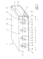
- Figure 1 show a perspective view of a cylinder head 1.
- the cylinder head 1 has a top face 1a, a bottom face 1b arranged to be connected to a cylinder block, a lateral exhaust flange face 1c arranged to be connected to an exhaust manifold, a second lateral face 1d being opposed to said lateral exhaust flange face 1c, a front face 1e and an end face 1f.
- the cylinder head 1 is provided with an integral coolant cross over passage 2 providing a first port 2a for connection to a first exhaust manifold cooling jacket outlet and extending between said first port 2a arranged at the lateral exhaust flange face 1c and a first coolant outlet 2b arranged at said second lateral face 1d, which is an inlet flange face arranged to be connected to an intake manifold 7.
- the cylinder head 1 is furthermore provided with an integral coolant short circuit passage 3 providing a second port 3a for connection to a second exhaust manifold cooling jacket outlet and extending between said second port 3a arranged at said lateral exhaust flange face 1c and a second coolant outlet 3b arranged at the bottom face 1b for connection to a coolant pump inlet.
- the cylinder head is provided with a coolant chamber 23, see fig 2, extending along a length axis 4 of the cylinder head 1.
- the coolant chamber 23 is arranged for cooling a plurality of exhaust channels 5a - 5h provided in the cylinder head 1.
- the lateral exhaust flange face 1c is provided with at least one outlet port 6a - 6d for each cylinder in said plurality of exhaust channels 5a - 5h.
- the outlet ports 6a - 6d are connected to said coolant chamber and are arranged to provide connections to a corresponding set of inlets arranged on an exhaust manifold cooling jacket.
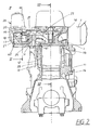
- the figures 2 - 12 show an internal combustion engine 11 in which a cylinder head 1 as described in figure 1 is used.
- the internal combustion engine is provided with several cylinders 12 for reciprocating pistons 13.
- the engine 11 has a cylinder block 14 to which a cylinder head 1 is bolted.
- An exhaust manifold assembly 40 including an exhaust manifold 17 is flanged on to an exhaust flange face 1c on the side of the cylinder head 1.
- the exhaust manifold 17 includes a set of exhaust inlet ducts arranged to form part of an exhaust outlet leading from a set of cylinders 12.
- the exhaust manifold 17 is surrounded by a cooling jacket 18.
- the cooling jacket 18 is divided by a partitioning wall 19 in the flow direction of the exhaust stream into a coolant inlet duct 20 and a coolant outlet duct 21.
- the exhaust manifold 17 communicates with at least one exhaust port 41 per cylinder 12.
- the coolant inlet duct 20 has a set of inlets 22 including at least one inlet 22a - 22d per cylinder 12, which is flow-connected to the coolant chamber 23 of the cylinder head 1 via the outlet ports 6a - 6d of the cylinder head 1.
- the coolant inlet duct 20 leads from said set of inlets 22 to an outlet opening 20a of said coolant inlet duct.
- the outlet opening 20a of the coolant inlet duct 20 is connected to an inlet opening 27 to a coolant chamber 28 arranged in a turbo charger assembly 26.
- the coolant outlet duct 21 extends between an inlet opening 21a of said coolant outlet duct via a thermostat space 32a at which the coolant outlet duct 21 is branched into a first and a second branch 21b, 21c provided with a first exhaust manifold cooling jacket outlet 21d and a second exhaust manifold cooling jacket outlet 21e.
- the coolant inlet duct 20 is connected to the coolant outlet duct 21 via at least one bypass opening 24.
- the exhaust manifold assembly 40 extends essentially along a longitudinal side of the cylinder head 1 between a front face 1e and an end face 1f.
- a thermostat space 32a is provided for a heat control valve 32, which takes the coolant stream coming in from the coolant outlet duct 21, either via a coolant cross-over passage 2 situated in the area of the front face 1e of the cylinder head 1 and the coolant outlet duct 35 to the heat exchanger 36 and, further on, to the coolant pump 37, or via a coolant short-circuiting passage 3 directly to the coolant pump 37.
- Fig. 7 shows the position of the control valve sliding sleeve 32b when the engine is warm, Fig. 8 when the engine is cold.
- the exhaust manifold 17 is connected to the turbine part 25 of a water-cooled turbocharger 26 on the side of the second end 30 of the exhaust manifold assembly 40 in the area of the end face 1f of the cylinder head 1.
- the coolant inlet 27 of the coolant chamber 28 of the turbocharger 26 is connected to the first coolant passage 20 of the exhaust manifold 17, the coolant outlet 29 to the second coolant passage 21 of the exhaust manifold 17.
- the coolant flow is indicated schematically by arrows P 1 ,P 1 .
- the coolant will flow from cylinder coolant chambers 39 in the crankcase 14 into coolant chambers 23 in the cylinder head 1, from where it passes through inlets coolant chambers 23 in the cylinder head 1, from where it passes through inlets 22 into the first coolant passage 20, upon which the coolant stream is divided.
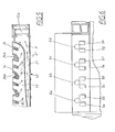
- the main stream in the first coolant passage 20, which is marked by full arrows P in Fig. 3, is passed to the turbine part 25 of the turbocharger 26, in the same flow direction as the exhaust gas in the exhaust manifold 17.
- the coolant stream flows through the coolant chambers 28 of the turbine part 25 of the turbocharger 26, and will reach the heat control valve 32 located at the front face 1e of the cylinder head 1 via the second coolant passage 21, against the flow direction of the exhaust stream.
- Secondary streams of the coolant will reach the second coolant passage 21 directly from the first coolant passage 20, via bypass openings 24. These secondary streams are entered in Fig. 3 by broken arrows P 1 . Secondary streams P 1 are controlled by predefined throttle cross-sections. Throttling may be achieved by providing precisely defined openings 24a (see Fig. 4) in the partitioning wall 19, or by restricted cross-sections 24b formed integral with the bypass openings 24, as shown in Fig. 5. With the aid of the secondary streams P 1 , a uniform temperature distribution will be obtained in the exhaust manifold assembly 40. In addition, excessive cooling of the turbine part 25 of the turbocharger 26 will be prevented.
- the heat control valve 32 will direct the coolant stream P to the coolant pump 37, either directly via a short-circuiting passage 38, or indirectly via a coolant cross-over passage 2. Once a certain, predefined coolant temperature is reached, the heat control valve 32 will open the flow path via the coolant cross-over passage 2 to a heat exchanger 36, in order to ensure sufficient cooling of the coolant. From the heat exchanger 36 the coolant will reach the coolant pump 37.
- the coolant cross-over passage 2 which departs from the exhaust flange face 1c and preferably extends to the inlet flange face 1d of an inlet manifold not shown in the drawings, is positioned at the front face 1e of the cylinder head 1, and, more preferably, cast integral therewith.
- the coolant short-circuiting passage 3 extending between the exhaust flange face 1c and the cylinder head sealing face 1d, is also cast integral with the cylinder head 1.
Landscapes
- Engineering & Computer Science (AREA)
- Chemical & Material Sciences (AREA)
- Combustion & Propulsion (AREA)
- Mechanical Engineering (AREA)
- General Engineering & Computer Science (AREA)
- Ocean & Marine Engineering (AREA)
- Exhaust Silencers (AREA)
- Cylinder Crankcases Of Internal Combustion Engines (AREA)
- Supercharger (AREA)
Claims (25)
- Abgaskrümmeranordnung (40) mit einem Abgaskrümmer (17), welcher zumindest teilweise von einem Kühlmantel (18) umgeben ist, dadurch gekennzeichnet, dass der Kühlmantel (18) einen ersten Abgaskrümmerkühlmantelauslass (21d), einen zweiten Abgaskrümmerkühlmantelauslass (21e) und einen Thermostatraum (32a) aufweist, an welchem eine Kühlmittelauslassleitung (21) in den ersten und zweiten Abgaskrümmerkühlmantelauslass (21d, 21e) verzweigt, wobei der Abgaskrümmer (17) eine Gruppe von Abgaseinlasskanälen (17a) aufweist, die zur Bildung eines Abschnitts eines Abgasauslasses angeordnet sind, der von einer Gruppe von Zylindern (12) herführt, und der Kühlmittelmantel (18) eine Kühlmitteleinlassleitung (20) besitzt, welcher mit einer Gruppe von Einlassöffnungen (22a bis 22d) versehen ist, wobei die Gruppe von Einlassöffnungen (22a bis 22d) zumindest eine Einlassöffnung (22a bis 22d) für jeden Zylinder in der Gruppe von Zylindern (12) aufweist.
- Abgaskrümmeranordnung nach Anspruch 1, dadurch gekennzeichnet, dass die Gruppe von Einlassöffnungen (22a bis 22d) mit einer korrespondierenden Gruppe von auf einem Zylinderkopf (1) angeordneten Auslassöffnungen (6a bis 6d) verbindbar angeordnet ist.
- Abgaskrümmeranordnung nach Anspruch 2, dadurch gekennzeichnet, dass die Kühlmitteleinlassleitung (20) mit einer Auslassöffnung (20a) versehen ist, welche mit einer Einlassöffnung (27) einer in einer Turboladerbaugruppe (26) angeordneten Kühlmittelkammer (28) verbindbar angeordnet ist.
- Abgaskrümmeranordnung nach einem der Ansprüche 2 bis 3, dadurch gekennzeichnet, dass der Abgaskrümmerkühlmantel (18) durch eine Trennwand (19) in die Kühlmitteleinlassleitung (20) und die Kühlmittelauslassleitung (21) aufgeteilt ist.
- Abgaskrümmeranordnung nach einem der Ansprüche 2 bis 4, dadurch gekennzeichnet, dass die Kühlmitteleinlassleitung (20) und die Kühlmittelauslassleitung (21) strömungsmäßig über zumindest eine Bypass-Öffnung (24) verbunden sind.
- Abgaskrümmeranordnung nach Anspruch 5, wobei der Abgaskrümmer (17) eine Gruppe von Abgaseinlasskanälen (17a) aufweist, dadurch gekennzeichnet, dass zumindest eine Bypass-Öffnung (24) pro Abgaseinlassleitung (17a) vorgesehen ist.
- Abgaskrümmeranordnung nach einem der Ansprüche 2 bis 6, dadurch gekennzeichnet, dass die Kühlmittelauslassleitung (21) einen größeren Querschnitt als die Kühlmitteleinlassleitung (20) aufweist.
- Abgaskrümmeranordnung nach einem der vorhergehenden Ansprüche, dadurch gekennzeichnet, dass sich die Kühlmittelauslassleitung (21) zwischen einer Einlassöffnung (21a) der Kühlmittelauslassleitung (21) und dem ersten und zweiten Abgaskrümmerkühlmantelauslass (21d, 21e) erstreckt.
- Abgaskrümmeranordnung nach Anspruch 8, dadurch gekennzeichnet, dass die Einlassöffnung der Kühlmittelauslassleitung (21) mit einer Auslassöffnung (29) von in einer Turboladerbaugruppe (26) angeordneten Kühlmittelkammer (28) verbindbar angeordnet ist.
- Brennkraftmaschine (11), welche einen Zylinderblock (14) mit einer Vielzahl von Zylindern (12), einen Zylinderkopf (1), der den Zylinderblock (14) verschließt, und eine Abgaskrümmeranordnung (40) mit einem Abgaskrümmer (17) aufweist, welcher zumindest teilweise von einem Kühlmantel (18) umgeben ist, dadurch gekennzeichnet, dass der Kühlmantel (18) einen ersten Abgaskrümmerkühlmantelauslass (21d), einen zweiten Abgaskrümmerkühlmantelauslass (21e) und einen Thermostatraum (32a) aufweist, an welchem eine Kühlmittelauslassleitung (21) in den ersten und zweiten Abgaskrümmerkühlmantelauslass (21d, 21e) verzweigt, wobei der Abgaskrümmer (17) eine Gruppe von Abgaseinlasskanälen (17a) aufweist, welche einen Abschnitt eines Abgasauslasses bilden, der von der Vielzahl von Zylindern (12) herführt, und der Kühlmittelmantel (18) eine Kühlmitteleinlassleitung (20) besitzt, welcher mit einer Gruppe von Einlassöffnungen (22a bis 22d) versehen ist, wobei die Gruppe von Einlassöffnungen (22a bis 22d) zumindest eine Einlassöffnung (22a bis 22d) für jeden Zylinder in der Vielzahl von Zylindern (12) aufweist.
- Brennkraftmaschine nach Anspruch 10, dadurch gekennzeichnet, dass die Gruppe von Einlassöffnungen (22a bis 22d) mit einer auf dem Zylinderkopf (1) angeordneten korrespondierenden Gruppe von Auslassöffnungen (6a bis 6d) verbunden ist.
- Brennkraftmaschine (11) nach Anspruch 11, dadurch gekennzeichnet, dass die Kühlmitteleinlassleitung (20) mit einer Auslassöffnung (20a) versehen ist, welche mit einer Auslassöffnung (27) zu einer in einer Turboladerbaugruppe (26) angeordneten Kühlmittelkammer (28) verbunden ist.
- Brennkraftmaschine nach einem der Ansprüche 11 bis 12, dadurch gekennzeichnet, dass der Abgaskrümmerkühlmantel (18) durch eine Trennwand (19) in die Kühlmitteleinlassleitung (20) und die Kühlmittelauslassleitung (21) aufgeteilt ist.
- Brennkraftmaschine nach einem der Ansprüche 11 bis 13, dadurch gekennzeichnet, dass die Kühlmitteleinlassleitung (20) und die Kühlmittelauslassleitung (21) strömungsmäßig über zumindest eine Bypass-Öffnung (24) verbunden sind.
- Brennkraftmaschine nach Anspruch 14, wobei der Abgaskrümmer (17) eine Gruppe von Abgaseinlasskanälen (17a) aufweist, dadurch gekennzeichnet, dass zumindest eine Bypass-Öffnung (24) pro Abgaseinlassleitung (17a) vorgesehen ist.
- Brennkraftmaschine nach einem der Ansprüche 11 bis 15, dadurch gekennzeichnet, dass die Kühlmittelauslassleitung (21) einen größeren Querschnitt als die Kühlmitteleinlassleitung (20) aufweist.
- Brennkraftmaschine nach einem der Ansprüche 11 bis 16, dadurch gekennzeichnet, dass sich die Kühlmittelauslassleitung (21) zwischen einer Einlassöffnung (21a) der Kühlmittelauslassleitung (21) und dem ersten und zweiten Abgaskrümmerkühlmantelauslass (21d, 21e) erstreckt.
- Brennkraftmaschine nach Anspruch 17, dadurch gekennzeichnet, dass die Einlassöffnung (21a) der Kühlmittelauslassleitung (21) mit einer Auslassöffnung (29) von einer in einer Turboladerbaugruppe (26) angeordneten Kühlmittelkammer (28) verbunden ist.
- Brennkraftmaschine nach einem der Ansprüche 11 bis 18, wobei der Zylinderkopf (1) eine Oberseite (1a), eine mit dem Zylinderblock (14) verbundene Unterseite (1b), eine mit der Abgaskrümmeranordnung (40) verbundene Abgasflanschquerseite (1c), eine zu der Abgasflanschquerseite (1c) gegenüber liegende zweite Querseite (1d), eine Vorderseite (1e) und eine Stirnseite (1f) aufweist, dadurch gekennzeichnet, dass der Zylinderkopf (1) mit einer integralen Kühlmitteldurchgangsleitung (2) versehen ist, welche eine erste Öffnung (2a) aufweist, die mit dem ersten Abgaskrümmerkühlmantelauslass (21d) verbunden ist, und sich zwischen der ersten Öffnung (2a), die an der Abgasflanschquerseite (1c) des Zylinderkopfs (1) angeordnet ist, und einer ersten Kühlmittelauslassleitung (2b) erstreckt, die an einer weiteren der Seiten (1a, 1b, 1d, 1e, 1f) angeordnet ist.
- Brennkraftmaschine nach Anspruch 19, dadurch gekennzeichnet, dass die erste Kühlmittelauslassleitung (2b) auf der zweiten Querseite (1d) angeordnet ist.
- Brennkraftmaschine nach Anspruch 20, dadurch gekennzeichnet, dass die zweite Querseite (1d) eine Einlassflanschseite ist, die mit einem Einlasskrümmer (7) verbunden ist.
- Brennkraftmaschine nach einem der Ansprüche 19 bis 21, dadurch gekennzeichnet, dass die integrale Kühlmitteldurchgangsleitung (2) mit einer Kühlmittelpumpe (37) über einen Wärmeaustauscher (36) verbunden ist.
- Brennkraftmaschine nach einem der Ansprüche 19 bis 22, dadurch gekennzeichnet, dass der Zylinderkopf (1) mit einer integralen Kühlmittelkurzschlussleitung (3) versehen ist, welche eine zweite Öffnung (3a) aufweist, die mit einem zweiten Auslass (21e) des Abgaskrümmerkühlmantels (18) verbunden ist und sich zwischen der zweiten Öffnung (3a), die an der Abgasflanschquerseite (1c) angeordnet ist, und einer zweiten Kühlmittelauslassleitung (3b) erstreckt, die an einer weiteren der Seiten (1a, 1b, 1d, 1e, 1f) angeordnet ist und zu einem Kühlmittelpumpeneinlass (36) führt.
- Brennkraftmaschine nach Anspruch 23, dadurch gekennzeichnet, dass die zweite Öffnung (3b) an der Unterseite (1b) vorgesehen ist.
- Brennkraftmaschine nach einem der Ansprüche 19 bis 24, wobei der Zylinderkopf (1) mit einer Kühlmittelkammer (23) versehen ist, die zur Kühlung einer in dem Zylinderkopf (1) vorgesehenen Vielzahl von Abgaskanälen (5a bis 5h) angeordnet ist, dadurch gekennzeichnet, dass die Abgasflanschquerseite (1c) mit zumindest einer Auslassöffnung (6a bis 6d) für jeden Zylinder in der Vielzahl von Zylindern (12) versehen ist, wobei die Auslassöffnungen (6a bis 6d) mit der Kühlmittelkammer (23) verbunden sind und Verbindungen zu einer korrespondierenden Gruppe von Einlässen (22a bis 22d) vorsehen, die an dem Abgaskrümmerkühlmantel (18) angeordnet sind.
Priority Applications (5)
| Application Number | Priority Date | Filing Date | Title |
|---|---|---|---|
| DE60305176T DE60305176T2 (de) | 2003-06-19 | 2003-06-19 | Abgaskrümmer und Brennkraftmaschine mit einem Abgaskrümmer |
| EP03076916A EP1498587B1 (de) | 2003-06-19 | 2003-06-19 | Abgaskrümmer und Brennkraftmaschine mit einem Abgaskrümmer |
| AT03076916T ATE325941T1 (de) | 2003-06-19 | 2003-06-19 | Abgaskrümmer und brennkraftmaschine mit einem abgaskrümmer |
| PCT/SE2004/000915 WO2004111400A1 (en) | 2003-06-19 | 2004-06-11 | Exhaust manifold and internal combustion engine comprising an exhaust manifold |
| US11/306,179 US20070056276A1 (en) | 2003-06-19 | 2005-12-19 | Exhaust manifold and internal combustion engine comprising an exhaust manifold |
Applications Claiming Priority (1)
| Application Number | Priority Date | Filing Date | Title |
|---|---|---|---|
| EP03076916A EP1498587B1 (de) | 2003-06-19 | 2003-06-19 | Abgaskrümmer und Brennkraftmaschine mit einem Abgaskrümmer |
Publications (2)
| Publication Number | Publication Date |
|---|---|
| EP1498587A1 EP1498587A1 (de) | 2005-01-19 |
| EP1498587B1 true EP1498587B1 (de) | 2006-05-10 |
Family
ID=33462168
Family Applications (1)
| Application Number | Title | Priority Date | Filing Date |
|---|---|---|---|
| EP03076916A Expired - Lifetime EP1498587B1 (de) | 2003-06-19 | 2003-06-19 | Abgaskrümmer und Brennkraftmaschine mit einem Abgaskrümmer |
Country Status (5)
| Country | Link |
|---|---|
| US (1) | US20070056276A1 (de) |
| EP (1) | EP1498587B1 (de) |
| AT (1) | ATE325941T1 (de) |
| DE (1) | DE60305176T2 (de) |
| WO (1) | WO2004111400A1 (de) |
Families Citing this family (8)
| Publication number | Priority date | Publication date | Assignee | Title |
|---|---|---|---|---|
| WO2007009139A1 (de) * | 2005-07-19 | 2007-01-25 | Avl List Gmbh | Abgasstrang einer brennkraftmaschine |
| WO2010020265A1 (de) * | 2008-08-20 | 2010-02-25 | Fev Motorentechnik Gmbh | Flexible nutzung der abgasenergie im betrieb einer brennkraftmaschine |
| AT511072B1 (de) * | 2011-06-22 | 2012-09-15 | Avl List Gmbh | Brennkraftmaschine mit zumindest einem zylinder |
| US20130000287A1 (en) * | 2011-06-29 | 2013-01-03 | Caterpillar Inc. | Exhaust manifold with shielded cooling |
| DE102012213936B4 (de) * | 2012-08-07 | 2025-08-07 | Ford Global Technologies, Llc | Aufgeladener Vier-Zylinder-Reihenmotor mit parallel angeordneten Turbinen und Verfahren zum Betreiben eines derartigen Vier-Zylinder-Reihenmotors |
| GB2562727B (en) * | 2017-05-22 | 2020-02-12 | Ford Global Tech Llc | A Motor Vehicle Cylinder Head |
| CN114233455B (zh) * | 2021-12-30 | 2023-04-18 | 潍柴动力股份有限公司 | 一种水套排气管及发动机 |
| JP7617868B2 (ja) | 2022-03-10 | 2025-01-20 | ヤンマーホールディングス株式会社 | エンジン |
Family Cites Families (13)
| Publication number | Priority date | Publication date | Assignee | Title |
|---|---|---|---|---|
| GB1553584A (en) * | 1976-04-08 | 1979-09-26 | Perkins Engines Ltd | Inlet and exhaust manifold assembly for an internal combustion engine |
| US4179884A (en) * | 1977-08-08 | 1979-12-25 | Caterpillar Tractor Co. | Watercooled exhaust manifold and method of making same |
| US4214443A (en) * | 1978-09-01 | 1980-07-29 | Perkins Engines Limited | Marine engine manifold |
| US4759181A (en) * | 1987-02-02 | 1988-07-26 | Biritz Ronald A | Manifold, apparatus and system for exhaust transfer and cooling of V-type marine engines |
| US4977741A (en) * | 1988-04-05 | 1990-12-18 | Brunswick Corporation | Combination exhaust manifold and exhaust elbow for marine propulsion system |
| JP2687140B2 (ja) * | 1988-07-05 | 1997-12-08 | 三信工業株式会社 | 舶用エンジンの冷却装置 |
| JP2724608B2 (ja) * | 1989-02-17 | 1998-03-09 | 三信工業株式会社 | 船舶用v型2サイクル内燃機関の水冷装置 |
| US5109668A (en) * | 1991-03-07 | 1992-05-05 | Brunswick Corporation | Marine exhaust manifold and elbow |
| JP3465515B2 (ja) * | 1997-01-31 | 2003-11-10 | スズキ株式会社 | 船外機の冷却装置 |
| DE19955302A1 (de) * | 1999-11-17 | 2001-05-23 | Deutz Ag | Flüssigkeitsgekühlte Brennkraftmaschine |
| US6454622B2 (en) * | 2000-01-17 | 2002-09-24 | Sanshin Kogyo Kabushiki Kaisha | Exhaust system for 4-cycle engine of small watercraft |
| CA2385797C (en) * | 2001-05-15 | 2009-07-14 | Honda Giken Kogyo Kabushiki Kaisha | Outboard motor |
| JP2003074340A (ja) * | 2001-09-04 | 2003-03-12 | Suzuki Motor Corp | 船外機の排気構造 |
-
2003
- 2003-06-19 EP EP03076916A patent/EP1498587B1/de not_active Expired - Lifetime
- 2003-06-19 AT AT03076916T patent/ATE325941T1/de not_active IP Right Cessation
- 2003-06-19 DE DE60305176T patent/DE60305176T2/de not_active Expired - Lifetime
-
2004
- 2004-06-11 WO PCT/SE2004/000915 patent/WO2004111400A1/en not_active Ceased
-
2005
- 2005-12-19 US US11/306,179 patent/US20070056276A1/en not_active Abandoned
Also Published As
| Publication number | Publication date |
|---|---|
| ATE325941T1 (de) | 2006-06-15 |
| US20070056276A1 (en) | 2007-03-15 |
| DE60305176T2 (de) | 2007-05-10 |
| EP1498587A1 (de) | 2005-01-19 |
| DE60305176D1 (de) | 2006-06-14 |
| WO2004111400A1 (en) | 2004-12-23 |
| WO2004111400B1 (en) | 2005-04-14 |
Similar Documents
| Publication | Publication Date | Title |
|---|---|---|
| EP1491739B1 (de) | Abgaskrümmer | |
| EP1099847B1 (de) | Kühlsystem für ruckgeführtes Abgas und Öl | |
| US6729272B2 (en) | Cylinder head cooling construction for an internal combustion engine | |
| US4620509A (en) | Twin-flow cooling system | |
| US6732679B2 (en) | Water-cooled internal combustion engine | |
| US20110197832A1 (en) | Coolant jackets for an internal combustion engine and method of control | |
| US4601265A (en) | Internal combustion engine with improved coolant arrangement | |
| EP1296033B1 (de) | Wasserkühlvorrichtung für eine vertikale Mehrzylinderbrennkraftmaschine | |
| US4493294A (en) | Cooling system of V-type internal combustion engine | |
| EP1498587B1 (de) | Abgaskrümmer und Brennkraftmaschine mit einem Abgaskrümmer | |
| JP3096090B2 (ja) | エンジン冷却装置 | |
| US11181033B2 (en) | Internal combustion engine body | |
| JP2003201842A (ja) | エンジンの冷却装置 | |
| JP4363176B2 (ja) | エンジンの排気還流装置 | |
| JP2003532017A (ja) | 多気筒内燃機関のための冷却循環装置 | |
| JP2019138282A (ja) | エンジン | |
| JP7172631B2 (ja) | エンジンの冷却構造 | |
| JP4411969B2 (ja) | エンジンの冷却装置 | |
| EP4253751B1 (de) | Agr-vorrichtung für einen verbrennungsmotor | |
| JP2917608B2 (ja) | 内燃機関の冷却装置 | |
| JP7172630B2 (ja) | エンジンの冷却構造 | |
| JP2006161782A (ja) | エンジンの冷却装置 | |
| JP3071546B2 (ja) | エンジンの冷却装置 | |
| WO2025052575A1 (ja) | エンジン | |
| JPH04342822A (ja) | 内燃機関の冷却水通路構造 |
Legal Events
| Date | Code | Title | Description |
|---|---|---|---|
| PUAI | Public reference made under article 153(3) epc to a published international application that has entered the european phase |
Free format text: ORIGINAL CODE: 0009012 |
|
| AK | Designated contracting states |
Kind code of ref document: A1 Designated state(s): AT BE BG CH CY CZ DE DK EE ES FI FR GB GR HU IE IT LI LU MC NL PT RO SE SI SK TR |
|
| AX | Request for extension of the european patent |
Extension state: AL LT LV MK |
|
| 17P | Request for examination filed |
Effective date: 20050503 |
|
| 17Q | First examination report despatched |
Effective date: 20050620 |
|
| AKX | Designation fees paid |
Designated state(s): AT BE BG CH CY CZ DE DK EE ES FI FR GB GR HU IE IT LI LU MC NL PT RO SE SI SK TR |
|
| GRAP | Despatch of communication of intention to grant a patent |
Free format text: ORIGINAL CODE: EPIDOSNIGR1 |
|
| GRAS | Grant fee paid |
Free format text: ORIGINAL CODE: EPIDOSNIGR3 |
|
| GRAA | (expected) grant |
Free format text: ORIGINAL CODE: 0009210 |
|
| AK | Designated contracting states |
Kind code of ref document: B1 Designated state(s): AT BE BG CH CY CZ DE DK EE ES FI FR GB GR HU IE IT LI LU MC NL PT RO SE SI SK TR |
|
| PG25 | Lapsed in a contracting state [announced via postgrant information from national office to epo] |
Ref country code: CZ Free format text: LAPSE BECAUSE OF FAILURE TO SUBMIT A TRANSLATION OF THE DESCRIPTION OR TO PAY THE FEE WITHIN THE PRESCRIBED TIME-LIMIT Effective date: 20060510 Ref country code: SI Free format text: LAPSE BECAUSE OF FAILURE TO SUBMIT A TRANSLATION OF THE DESCRIPTION OR TO PAY THE FEE WITHIN THE PRESCRIBED TIME-LIMIT Effective date: 20060510 Ref country code: SK Free format text: LAPSE BECAUSE OF FAILURE TO SUBMIT A TRANSLATION OF THE DESCRIPTION OR TO PAY THE FEE WITHIN THE PRESCRIBED TIME-LIMIT Effective date: 20060510 Ref country code: BE Free format text: LAPSE BECAUSE OF FAILURE TO SUBMIT A TRANSLATION OF THE DESCRIPTION OR TO PAY THE FEE WITHIN THE PRESCRIBED TIME-LIMIT Effective date: 20060510 Ref country code: NL Free format text: LAPSE BECAUSE OF FAILURE TO SUBMIT A TRANSLATION OF THE DESCRIPTION OR TO PAY THE FEE WITHIN THE PRESCRIBED TIME-LIMIT Effective date: 20060510 Ref country code: CH Free format text: LAPSE BECAUSE OF FAILURE TO SUBMIT A TRANSLATION OF THE DESCRIPTION OR TO PAY THE FEE WITHIN THE PRESCRIBED TIME-LIMIT Effective date: 20060510 Ref country code: AT Free format text: LAPSE BECAUSE OF FAILURE TO SUBMIT A TRANSLATION OF THE DESCRIPTION OR TO PAY THE FEE WITHIN THE PRESCRIBED TIME-LIMIT Effective date: 20060510 Ref country code: FI Free format text: LAPSE BECAUSE OF FAILURE TO SUBMIT A TRANSLATION OF THE DESCRIPTION OR TO PAY THE FEE WITHIN THE PRESCRIBED TIME-LIMIT Effective date: 20060510 Ref country code: LI Free format text: LAPSE BECAUSE OF FAILURE TO SUBMIT A TRANSLATION OF THE DESCRIPTION OR TO PAY THE FEE WITHIN THE PRESCRIBED TIME-LIMIT Effective date: 20060510 Ref country code: RO Free format text: LAPSE BECAUSE OF FAILURE TO SUBMIT A TRANSLATION OF THE DESCRIPTION OR TO PAY THE FEE WITHIN THE PRESCRIBED TIME-LIMIT Effective date: 20060510 |
|
| REG | Reference to a national code |
Ref country code: GB Ref legal event code: FG4D |
|
| REG | Reference to a national code |
Ref country code: CH Ref legal event code: EP |
|
| REF | Corresponds to: |
Ref document number: 60305176 Country of ref document: DE Date of ref document: 20060614 Kind code of ref document: P |
|
| REG | Reference to a national code |
Ref country code: IE Ref legal event code: FG4D |
|
| PG25 | Lapsed in a contracting state [announced via postgrant information from national office to epo] |
Ref country code: IE Free format text: LAPSE BECAUSE OF NON-PAYMENT OF DUE FEES Effective date: 20060619 |
|
| PG25 | Lapsed in a contracting state [announced via postgrant information from national office to epo] |
Ref country code: MC Free format text: LAPSE BECAUSE OF NON-PAYMENT OF DUE FEES Effective date: 20060630 |
|
| PG25 | Lapsed in a contracting state [announced via postgrant information from national office to epo] |
Ref country code: SE Free format text: LAPSE BECAUSE OF FAILURE TO SUBMIT A TRANSLATION OF THE DESCRIPTION OR TO PAY THE FEE WITHIN THE PRESCRIBED TIME-LIMIT Effective date: 20060810 Ref country code: DK Free format text: LAPSE BECAUSE OF FAILURE TO SUBMIT A TRANSLATION OF THE DESCRIPTION OR TO PAY THE FEE WITHIN THE PRESCRIBED TIME-LIMIT Effective date: 20060810 |
|
| PG25 | Lapsed in a contracting state [announced via postgrant information from national office to epo] |
Ref country code: ES Free format text: LAPSE BECAUSE OF FAILURE TO SUBMIT A TRANSLATION OF THE DESCRIPTION OR TO PAY THE FEE WITHIN THE PRESCRIBED TIME-LIMIT Effective date: 20060821 |
|
| PG25 | Lapsed in a contracting state [announced via postgrant information from national office to epo] |
Ref country code: PT Free format text: LAPSE BECAUSE OF FAILURE TO SUBMIT A TRANSLATION OF THE DESCRIPTION OR TO PAY THE FEE WITHIN THE PRESCRIBED TIME-LIMIT Effective date: 20061010 |
|
| NLV1 | Nl: lapsed or annulled due to failure to fulfill the requirements of art. 29p and 29m of the patents act | ||
| REG | Reference to a national code |
Ref country code: CH Ref legal event code: PL |
|
| PLBE | No opposition filed within time limit |
Free format text: ORIGINAL CODE: 0009261 |
|
| STAA | Information on the status of an ep patent application or granted ep patent |
Free format text: STATUS: NO OPPOSITION FILED WITHIN TIME LIMIT |
|
| 26N | No opposition filed |
Effective date: 20070213 |
|
| EN | Fr: translation not filed | ||
| PG25 | Lapsed in a contracting state [announced via postgrant information from national office to epo] |
Ref country code: GR Free format text: LAPSE BECAUSE OF FAILURE TO SUBMIT A TRANSLATION OF THE DESCRIPTION OR TO PAY THE FEE WITHIN THE PRESCRIBED TIME-LIMIT Effective date: 20060811 Ref country code: FR Free format text: LAPSE BECAUSE OF FAILURE TO SUBMIT A TRANSLATION OF THE DESCRIPTION OR TO PAY THE FEE WITHIN THE PRESCRIBED TIME-LIMIT Effective date: 20070309 |
|
| PG25 | Lapsed in a contracting state [announced via postgrant information from national office to epo] |
Ref country code: EE Free format text: LAPSE BECAUSE OF FAILURE TO SUBMIT A TRANSLATION OF THE DESCRIPTION OR TO PAY THE FEE WITHIN THE PRESCRIBED TIME-LIMIT Effective date: 20060510 Ref country code: BG Free format text: LAPSE BECAUSE OF FAILURE TO SUBMIT A TRANSLATION OF THE DESCRIPTION OR TO PAY THE FEE WITHIN THE PRESCRIBED TIME-LIMIT Effective date: 20060810 |
|
| PG25 | Lapsed in a contracting state [announced via postgrant information from national office to epo] |
Ref country code: HU Free format text: LAPSE BECAUSE OF FAILURE TO SUBMIT A TRANSLATION OF THE DESCRIPTION OR TO PAY THE FEE WITHIN THE PRESCRIBED TIME-LIMIT Effective date: 20061111 Ref country code: TR Free format text: LAPSE BECAUSE OF FAILURE TO SUBMIT A TRANSLATION OF THE DESCRIPTION OR TO PAY THE FEE WITHIN THE PRESCRIBED TIME-LIMIT Effective date: 20060510 Ref country code: LU Free format text: LAPSE BECAUSE OF NON-PAYMENT OF DUE FEES Effective date: 20060619 |
|
| PG25 | Lapsed in a contracting state [announced via postgrant information from national office to epo] |
Ref country code: FR Free format text: LAPSE BECAUSE OF FAILURE TO SUBMIT A TRANSLATION OF THE DESCRIPTION OR TO PAY THE FEE WITHIN THE PRESCRIBED TIME-LIMIT Effective date: 20060510 Ref country code: CY Free format text: LAPSE BECAUSE OF FAILURE TO SUBMIT A TRANSLATION OF THE DESCRIPTION OR TO PAY THE FEE WITHIN THE PRESCRIBED TIME-LIMIT Effective date: 20060510 |
|
| PGFP | Annual fee paid to national office [announced via postgrant information from national office to epo] |
Ref country code: GB Payment date: 20150604 Year of fee payment: 13 Ref country code: DE Payment date: 20150604 Year of fee payment: 13 |
|
| PGFP | Annual fee paid to national office [announced via postgrant information from national office to epo] |
Ref country code: IT Payment date: 20150618 Year of fee payment: 13 |
|
| REG | Reference to a national code |
Ref country code: DE Ref legal event code: R119 Ref document number: 60305176 Country of ref document: DE |
|
| GBPC | Gb: european patent ceased through non-payment of renewal fee |
Effective date: 20160619 |
|
| PG25 | Lapsed in a contracting state [announced via postgrant information from national office to epo] |
Ref country code: DE Free format text: LAPSE BECAUSE OF NON-PAYMENT OF DUE FEES Effective date: 20170103 |
|
| PG25 | Lapsed in a contracting state [announced via postgrant information from national office to epo] |
Ref country code: GB Free format text: LAPSE BECAUSE OF NON-PAYMENT OF DUE FEES Effective date: 20160619 |
|
| PG25 | Lapsed in a contracting state [announced via postgrant information from national office to epo] |
Ref country code: IT Free format text: LAPSE BECAUSE OF NON-PAYMENT OF DUE FEES Effective date: 20160619 |