EP1498596A2 - Joint d'étanchéité à fente étrangleur pour soupapes - Google Patents
Joint d'étanchéité à fente étrangleur pour soupapes Download PDFInfo
- Publication number
- EP1498596A2 EP1498596A2 EP04016087A EP04016087A EP1498596A2 EP 1498596 A2 EP1498596 A2 EP 1498596A2 EP 04016087 A EP04016087 A EP 04016087A EP 04016087 A EP04016087 A EP 04016087A EP 1498596 A2 EP1498596 A2 EP 1498596A2
- Authority
- EP
- European Patent Office
- Prior art keywords
- actuator
- insert
- valve
- throttle
- housing
- Prior art date
- Legal status (The legal status is an assumption and is not a legal conclusion. Google has not performed a legal analysis and makes no representation as to the accuracy of the status listed.)
- Granted
Links
Images



Classifications
-
- F—MECHANICAL ENGINEERING; LIGHTING; HEATING; WEAPONS; BLASTING
- F02—COMBUSTION ENGINES; HOT-GAS OR COMBUSTION-PRODUCT ENGINE PLANTS
- F02D—CONTROLLING COMBUSTION ENGINES
- F02D9/00—Controlling engines by throttling air or fuel-and-air induction conduits or exhaust conduits
- F02D9/08—Throttle valves specially adapted therefor; Arrangements of such valves in conduits
- F02D9/10—Throttle valves specially adapted therefor; Arrangements of such valves in conduits having pivotally-mounted flaps
Definitions
- the invention relates to a throttle gap seal according to the preamble of the claim 1 for valves that control the flow of gaseous media in internal combustion engines control cyclically (i.e., per work cycle) and in closed mode State show very low leakage rates.
- the invention proposes a throttle gap seal according to the features of claim 1 before.
- the throttle gap seal according to the invention thus has an insert, the is received in the housing. This is to the housing with at least one Seal sealed.
- the insert comprises the flow cross section of the Housing and can, in the closed state of the valve, with his the actuator of the valve facing sealing surface on the position of the actuator with the insert facing sealing surface at least once align in the housing.
- the sealing surface of the insert and the sealing surface of the actuator without continuous force on each other in the closed Position of the valve opposite. Insert and actuator are thus powerless compared.
- the actuator takes its rest-closed position without a stop against the insert and housing.
- a stop By dispensing with a stop can avoid extreme acceleration peaks of the moving parts.
- the seal preferably takes on additional weight in addition to the medium seal Functions, such as the thermal insulation between housing and insert and / or the attachment of the insert in the housing.
- This case of thermal Isolation concerns in particular the static aspect.
- the thermal insulation between the housing and insert represents in particular in the event that the valve is located in the area of a cylinder head, sure that the Heating the housing does not transfer to the insert, and thus a caused high temperature difference between the actuator and insert.
- the actuator and the insert part a similar quotient of medium washed component surfaces / heat capacity of the component, to a similar timing behavior to achieve the thermal expansion of the components.
- This training of actuator and insert considered in particular effects due to strong intake air heating in turbocharged engines.
- the actuator of one or consists of several individual components, some of one or more materials low density, such as light metal, metal foam, plastic foam, fiber reinforced plastic are made.
- the insert can be in the closed state of Valve with its the actuator facing sealing surface at least once to the position of the actuator with the insert facing the sealing surface align in the housing.
- the throttle sealing gap between the actuator and insert by positioning the insert in the plane or in addition is adjustable perpendicular to the plane. This positioning can be done by mechanical (for example, distance gauge), optical (for example, light gap measurement) or calibrate hydraulic (for example gap flow) the throttle sealing gap are made.
- the calibration of the throttle sealing gap can also by self-centering of the insert on the actuator respectively. This is preferably done by applying the sealing surface of Valve on the sealing surface of the insert, wherein one of these surfaces with a thick coating is provided, which the throttle gap in the assembled state at least partially closes and in the later operation of the valve at the opposite, wear-resistant sealing surface removes.
- aligning the insert in the housing results the throttle sealing gap by automatically returning the alignment of the Insert on the actuator in the rest-closed position. This will be for example by a decreasing throttle gap height in the direction of the rest-closing position reached.
- the insert closes movable, but medium-tight via seals to the housing and it are the sealing surfaces of insert and actuator provided with a wear-resistant surface coating.
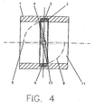
- valve 16 has a housing 1 for guiding the gaseous medium in the valve 16.
- a housing 1 for guiding the gaseous medium in the valve 16.
- the housing 1 is a movable drivable, about the axis of rotation 24 pivotable actuator 4 to change the corresponding flow cross section 11 provided in the valve.
- an insert 2 is added in the Housing 1, which is the housing 1 with a seal 3 sealed.
- the insert part 2 comprises the flow cross-section 11 of the housing 1.
- the actuator 4 is shown in its closed position.
- the insert 2 can be in the closed state 6 of the valve in its the actuator 4 facing sealing surface 10, as illustrated in particular in Figure 2 is, on the position of the actuator 4 with the insert 2 facing Align sealing surface 8 at least once in the housing and forms a throttle gap 12.
- the sealing surface 10 of the insert 2 and the sealing surface 8 of the Actuator 4 are, without continuous force on each other, in the closed position 6 of the valve opposite.
- the actuator 4 takes its Closed position 6 without a stop against the insert 2 and housing 1 a.
- the sealing surface 8 of the actuator 4 results in changing the flow cross-section 11 of the valve with respect to the sealing surface 10 a circular trajectory 9 off.
- the trajectory of the sealing surface 8 to the rest-closed position 6 of the actuator 4 includes a tangential direction 7 opposite the sealing surface 10.
- the longitudinal center axis of the housing 1 is denoted by the reference numeral 14, which is vertical to the throttle sealing gap 12 arranged plane designated by the reference numeral 15.
- the actuator 4 In the rest position, the actuator 4 is symmetrical to the plane 15.
- the reference numeral 5 is the opened, thus pivoted by 90 ° position designated the actuator 4.
- the reference numeral 13 is a position of the actuator 4 upon release or closing of the flow cross-section 11 illustrates.
- the throttle sealing gap 12 is during the closing process the valve even before reaching the rest-closing position 6 of the actuator. 4 from this position 13, whereby the actuator when closing the Flow cross section 11 imposes a movement speed greater than zero becomes.
- the throttle sealing gap 12 remains during the opening process of the Valve for a portion of the onset movement of the actuator. 4 obtained from its rest-closed position 6 out to its position 13, whereby the actuator 4 at the beginning of the release of the flow cross section 11th a movement speed greater than zero is imposed.
- the actuator 4 and the insert 2 is made of a material having similar Thermal expansion coefficients.
- the seal 3 takes over, in addition to the medium seal, additional features, especially the thermal isolation between Housing 1 and insert 2 and / or the attachment of the insert part 2 in the housing 1.
- the actuator 4 and the insert 2 have a similar Coefficient of medium flow around the surface of the component / heat capacity of the medium Component, to a similar time behavior with respect to the thermal expansion to reach the components.
- the actuator 4 is the component surfaces 22 and 23 and formed by the sealing surface 8 of the actuator 4 Part surface, and the insert 2 to the component surfaces 17th and 18 and the sealing surface 10 of the insert 2, which is another Component surface forms.
- the actuator 4 has in the exemplary embodiment a circular disk-shaped outer contour, the at least the flow cross-section 11 in the closed Position of the valve 6 to the throttle gap 12 closes.
- the actuator 4 in principle may consist of one or more individual components, the actuator 4, the partly from one or more low density materials, such as Light metal, metal foam, plastic foam, fiber-reinforced plastic are made.
- the insert 2 may consist of several individual components consist.
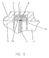
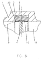
- FIGS. 5 to 7 illustrate the particular design of the throttle gap seal based on three basic embodiments, the self-centering of the insert 2 to reach the actuator 4:
- the self-centering of the insert takes place 2 on the actuator 4 by applying the sealing surface 8 of the actuator 4 on the sealing surface 10 of the insert part 2, wherein the sealing surface 8 of the actuator 4 is provided with a coating 19.
- the embodiment according to FIG. 6 differs from that according to FIG 5 only in that instead of the coating 19 of the actuator 4 a Coating 20 of the insert 2 is provided, which at least the throttle gap in the assembled state closes or shrinks and in later operation the valve on the opposite, wear-resistant sealing surface 8 of the Actuator 4 at least partially removes.
- FIG 7 illustrates an embodiment in which the throttle sealing gap 12 by automatically returning the alignment of the insert 2 on the actuator 4 in the rest-closed position 6 results. This will be for example by a decreasing throttle gap height 21 in the direction of the rest-closing position 6 reached.
- the insert 2 closes movable, but medium-tight via two seals 3 to the housing 1 and it is the sealing surfaces. 8 and 10 provided with a wear-resistant surface coating. At this Embodiment, the insert 2 is fixed elastically in the housing 1.
Landscapes
- Engineering & Computer Science (AREA)
- Chemical & Material Sciences (AREA)
- Combustion & Propulsion (AREA)
- Mechanical Engineering (AREA)
- General Engineering & Computer Science (AREA)
- Lift Valve (AREA)
- Valve Device For Special Equipments (AREA)
Applications Claiming Priority (2)
| Application Number | Priority Date | Filing Date | Title |
|---|---|---|---|
| DE10332766 | 2003-07-17 | ||
| DE10332766 | 2003-07-17 |
Publications (3)
| Publication Number | Publication Date |
|---|---|
| EP1498596A2 true EP1498596A2 (fr) | 2005-01-19 |
| EP1498596A3 EP1498596A3 (fr) | 2005-06-08 |
| EP1498596B1 EP1498596B1 (fr) | 2006-10-18 |
Family
ID=33461995
Family Applications (1)
| Application Number | Title | Priority Date | Filing Date |
|---|---|---|---|
| EP20040016087 Expired - Lifetime EP1498596B1 (fr) | 2003-07-17 | 2004-07-08 | Joint d'étanchéité à fente étrangleur pour soupapes |
Country Status (2)
| Country | Link |
|---|---|
| EP (1) | EP1498596B1 (fr) |
| DE (1) | DE502004001773D1 (fr) |
Cited By (4)
| Publication number | Priority date | Publication date | Assignee | Title |
|---|---|---|---|---|
| EP1826375A1 (fr) * | 2006-02-24 | 2007-08-29 | Mahle International GmbH | Soupape de commutation et son procédé de fabrication |
| WO2008145500A1 (fr) * | 2007-05-29 | 2008-12-04 | Mahle International Gmbh | Soupape de commande |
| EP2017510A1 (fr) * | 2007-06-12 | 2009-01-21 | Arno Hofmann | Vanne à écluse rotative écoulant de gaz |
| DE102012009878B3 (de) * | 2012-05-18 | 2013-06-13 | Gerhard Kirstein | Verbrennungsmotor |
Family Cites Families (4)
| Publication number | Priority date | Publication date | Assignee | Title |
|---|---|---|---|---|
| JPH10103089A (ja) * | 1996-09-25 | 1998-04-21 | Aisan Ind Co Ltd | 吸気装置 |
| JP2002295273A (ja) * | 2001-01-29 | 2002-10-09 | Denso Corp | インサート成形体およびそれにより形成されたスロットルボディ |
| DE10138931A1 (de) * | 2001-08-08 | 2003-03-06 | Bosch Gmbh Robert | Drosselvorrichtungsgehäuse mit flexiblen Ausgleichselementen für Brennkraftmaschinen |
| JP2003184583A (ja) * | 2001-12-20 | 2003-07-03 | Aisan Ind Co Ltd | 絞り弁装置 |
-
2004
- 2004-07-08 EP EP20040016087 patent/EP1498596B1/fr not_active Expired - Lifetime
- 2004-07-08 DE DE200450001773 patent/DE502004001773D1/de not_active Expired - Lifetime
Cited By (5)
| Publication number | Priority date | Publication date | Assignee | Title |
|---|---|---|---|---|
| EP1826375A1 (fr) * | 2006-02-24 | 2007-08-29 | Mahle International GmbH | Soupape de commutation et son procédé de fabrication |
| US7637278B2 (en) | 2006-02-24 | 2009-12-29 | Mahle International Gmbh | Switching valve and respective manufacturing method |
| WO2008145500A1 (fr) * | 2007-05-29 | 2008-12-04 | Mahle International Gmbh | Soupape de commande |
| EP2017510A1 (fr) * | 2007-06-12 | 2009-01-21 | Arno Hofmann | Vanne à écluse rotative écoulant de gaz |
| DE102012009878B3 (de) * | 2012-05-18 | 2013-06-13 | Gerhard Kirstein | Verbrennungsmotor |
Also Published As
| Publication number | Publication date |
|---|---|
| EP1498596B1 (fr) | 2006-10-18 |
| EP1498596A3 (fr) | 2005-06-08 |
| DE502004001773D1 (de) | 2006-11-30 |
Similar Documents
| Publication | Publication Date | Title |
|---|---|---|
| DE4423657A1 (de) | Betätigungseinrichtung für ein Motorbremsventil einer Brennkraftmaschine | |
| DE19947848A1 (de) | Aktuator zur Betätigung eines Stellgliedes, insbesondere eines Gaswechselventils mit einseitiger Federanordnung | |
| EP1893855B1 (fr) | Soupape de derivation pour moteurs a combustion interne | |
| DE102013210350A1 (de) | Metallverstärkte dichtungsplatte für vorgesteuertes schieberventil | |
| DE3808542A1 (de) | Ventiltrieb fuer ein gaswechselventil einer brennkraftmaschine | |
| DE19828199A1 (de) | Absperrventil | |
| EP1498596B1 (fr) | Joint d'étanchéité à fente étrangleur pour soupapes | |
| DE2363719A1 (de) | Ventil fuer die installation in abgasrueckfuehrleitungen von verbrennungskraftmaschinen | |
| DE3826974A1 (de) | Stelleinrichtung fuer ein gaswechselventil | |
| DE3913912A1 (de) | Hydraulischer einrohr-gasdruck-stossdaempfer | |
| EP0326787B1 (fr) | Vanne à tiroir | |
| DE3311280A1 (de) | Hydraulisches ventilspielausgleichselement | |
| DE2157222A1 (de) | Ventiltrieb fur Verbrennungsmotoren | |
| DE19805446A1 (de) | Hydraulische Schalteinheit | |
| EP1783341A1 (fr) | Générateur à swirl ou tumble | |
| DE803010C (de) | Hydraulische Vorrichtung zur Nachstellung des Ventilspieles bei Brennkraftmaschinen | |
| DE102013213820B4 (de) | Gaswechselventil | |
| DE19737967A1 (de) | Vorrichtung zum Betätigen eines Gaswechselventils mit einem elektromagnetischen Aktuator | |
| DE1177444B (de) | Vorrichtung zur Daempfung der Schliess- bzw. OEffnungsbewegung eines ueber einen Antriebs-kolben druckmittelbetaetigten Ventils od. dgl. | |
| DE3016823A1 (de) | Anordnung zum spuelen und laden der zylinder einer zweitaktbrennkraftmaschine | |
| DE4307715A1 (de) | Neuartige Ventilsteuerung mit Kolbenbodenventilen für 4-Takt-Verbrennungsmotore (Zwangssteuerung) | |
| DE3106542A1 (de) | Ventiltrieb eines viertakt-hubkolben-verbrennungsmotors | |
| DE3445998C2 (de) | Druckmittelbetätigtes Stellglied | |
| DE102005052423B4 (de) | Vorrichtung zur Impulsaufladung einer Brennkraftmaschine | |
| DE1249616B (fr) |
Legal Events
| Date | Code | Title | Description |
|---|---|---|---|
| PUAI | Public reference made under article 153(3) epc to a published international application that has entered the european phase |
Free format text: ORIGINAL CODE: 0009012 |
|
| AK | Designated contracting states |
Kind code of ref document: A2 Designated state(s): AT BE BG CH CY CZ DE DK EE ES FI FR GB GR HU IE IT LI LU MC NL PL PT RO SE SI SK TR |
|
| AX | Request for extension of the european patent |
Extension state: AL HR LT LV MK |
|
| PUAL | Search report despatched |
Free format text: ORIGINAL CODE: 0009013 |
|
| AK | Designated contracting states |
Kind code of ref document: A3 Designated state(s): AT BE BG CH CY CZ DE DK EE ES FI FR GB GR HU IE IT LI LU MC NL PL PT RO SE SI SK TR |
|
| AX | Request for extension of the european patent |
Extension state: AL HR LT LV MK |
|
| 17P | Request for examination filed |
Effective date: 20050513 |
|
| AKX | Designation fees paid |
Designated state(s): DE FR GB |
|
| GRAP | Despatch of communication of intention to grant a patent |
Free format text: ORIGINAL CODE: EPIDOSNIGR1 |
|
| GRAS | Grant fee paid |
Free format text: ORIGINAL CODE: EPIDOSNIGR3 |
|
| GRAA | (expected) grant |
Free format text: ORIGINAL CODE: 0009210 |
|
| AK | Designated contracting states |
Kind code of ref document: B1 Designated state(s): DE FR GB |
|
| REG | Reference to a national code |
Ref country code: GB Ref legal event code: FG4D Free format text: NOT ENGLISH |
|
| REF | Corresponds to: |
Ref document number: 502004001773 Country of ref document: DE Date of ref document: 20061130 Kind code of ref document: P |
|
| GBT | Gb: translation of ep patent filed (gb section 77(6)(a)/1977) |
Effective date: 20061220 |
|
| ET | Fr: translation filed | ||
| PLBI | Opposition filed |
Free format text: ORIGINAL CODE: 0009260 |
|
| PLAX | Notice of opposition and request to file observation + time limit sent |
Free format text: ORIGINAL CODE: EPIDOSNOBS2 |
|
| 26 | Opposition filed |
Opponent name: MAHLE INTERNATIONAL GMBH Effective date: 20070717 |
|
| PLAF | Information modified related to communication of a notice of opposition and request to file observations + time limit |
Free format text: ORIGINAL CODE: EPIDOSCOBS2 |
|
| PLBP | Opposition withdrawn |
Free format text: ORIGINAL CODE: 0009264 |
|
| PLBD | Termination of opposition procedure: decision despatched |
Free format text: ORIGINAL CODE: EPIDOSNOPC1 |
|
| PLAS | Information related to reply of patent proprietor to notice(s) of opposition deleted |
Free format text: ORIGINAL CODE: EPIDOSDOBS3 |
|
| PLBB | Reply of patent proprietor to notice(s) of opposition received |
Free format text: ORIGINAL CODE: EPIDOSNOBS3 |
|
| PLBM | Termination of opposition procedure: date of legal effect published |
Free format text: ORIGINAL CODE: 0009276 |
|
| STAA | Information on the status of an ep patent application or granted ep patent |
Free format text: STATUS: OPPOSITION PROCEDURE CLOSED |
|
| 27C | Opposition proceedings terminated |
Effective date: 20080301 |
|
| PGFP | Annual fee paid to national office [announced via postgrant information from national office to epo] |
Ref country code: GB Payment date: 20120719 Year of fee payment: 9 |
|
| GBPC | Gb: european patent ceased through non-payment of renewal fee |
Effective date: 20130708 |
|
| PG25 | Lapsed in a contracting state [announced via postgrant information from national office to epo] |
Ref country code: GB Free format text: LAPSE BECAUSE OF NON-PAYMENT OF DUE FEES Effective date: 20130708 |
|
| REG | Reference to a national code |
Ref country code: FR Ref legal event code: PLFP Year of fee payment: 13 |
|
| REG | Reference to a national code |
Ref country code: FR Ref legal event code: PLFP Year of fee payment: 14 |
|
| REG | Reference to a national code |
Ref country code: FR Ref legal event code: PLFP Year of fee payment: 15 |
|
| PGFP | Annual fee paid to national office [announced via postgrant information from national office to epo] |
Ref country code: DE Payment date: 20220727 Year of fee payment: 19 |
|
| PGFP | Annual fee paid to national office [announced via postgrant information from national office to epo] |
Ref country code: FR Payment date: 20220725 Year of fee payment: 19 |
|
| REG | Reference to a national code |
Ref country code: DE Ref legal event code: R119 Ref document number: 502004001773 Country of ref document: DE |
|
| PG25 | Lapsed in a contracting state [announced via postgrant information from national office to epo] |
Ref country code: DE Free format text: LAPSE BECAUSE OF NON-PAYMENT OF DUE FEES Effective date: 20240201 |
|
| PG25 | Lapsed in a contracting state [announced via postgrant information from national office to epo] |
Ref country code: FR Free format text: LAPSE BECAUSE OF NON-PAYMENT OF DUE FEES Effective date: 20230731 |