EP1498611A1 - Compresseur à vis - Google Patents
Compresseur à vis Download PDFInfo
- Publication number
- EP1498611A1 EP1498611A1 EP04012535A EP04012535A EP1498611A1 EP 1498611 A1 EP1498611 A1 EP 1498611A1 EP 04012535 A EP04012535 A EP 04012535A EP 04012535 A EP04012535 A EP 04012535A EP 1498611 A1 EP1498611 A1 EP 1498611A1
- Authority
- EP
- European Patent Office
- Prior art keywords
- screw compressor
- compressor according
- spool
- screw
- displacement
- Prior art date
- Legal status (The legal status is an assumption and is not a legal conclusion. Google has not performed a legal analysis and makes no representation as to the accuracy of the status listed.)
- Withdrawn
Links
- 238000006073 displacement reaction Methods 0.000 claims abstract description 29
- 230000006835 compression Effects 0.000 claims abstract description 10
- 238000007906 compression Methods 0.000 claims abstract description 10
- 239000003507 refrigerant Substances 0.000 claims abstract description 4
- 239000000523 sample Substances 0.000 claims description 10
- 238000005259 measurement Methods 0.000 abstract 1
- 230000002349 favourable effect Effects 0.000 description 3
- 230000008878 coupling Effects 0.000 description 2
- 238000010168 coupling process Methods 0.000 description 2
- 238000005859 coupling reaction Methods 0.000 description 2
- 238000003780 insertion Methods 0.000 description 2
- 230000037431 insertion Effects 0.000 description 2
- 230000003287 optical effect Effects 0.000 description 2
- 241001422033 Thestylus Species 0.000 description 1
- 230000009286 beneficial effect Effects 0.000 description 1
- 238000001514 detection method Methods 0.000 description 1
- 230000001939 inductive effect Effects 0.000 description 1
- 238000012544 monitoring process Methods 0.000 description 1
Images

Classifications
-
- F—MECHANICAL ENGINEERING; LIGHTING; HEATING; WEAPONS; BLASTING
- F04—POSITIVE - DISPLACEMENT MACHINES FOR LIQUIDS; PUMPS FOR LIQUIDS OR ELASTIC FLUIDS
- F04C—ROTARY-PISTON, OR OSCILLATING-PISTON, POSITIVE-DISPLACEMENT MACHINES FOR LIQUIDS; ROTARY-PISTON, OR OSCILLATING-PISTON, POSITIVE-DISPLACEMENT PUMPS
- F04C28/00—Control of, monitoring of, or safety arrangements for, pumps or pumping installations specially adapted for elastic fluids
- F04C28/10—Control of, monitoring of, or safety arrangements for, pumps or pumping installations specially adapted for elastic fluids characterised by changing the positions of the inlet or outlet openings with respect to the working chamber
- F04C28/12—Control of, monitoring of, or safety arrangements for, pumps or pumping installations specially adapted for elastic fluids characterised by changing the positions of the inlet or outlet openings with respect to the working chamber using sliding valves
- F04C28/125—Control of, monitoring of, or safety arrangements for, pumps or pumping installations specially adapted for elastic fluids characterised by changing the positions of the inlet or outlet openings with respect to the working chamber using sliding valves with sliding valves controlled by the use of fluid other than the working fluid
-
- F—MECHANICAL ENGINEERING; LIGHTING; HEATING; WEAPONS; BLASTING
- F04—POSITIVE - DISPLACEMENT MACHINES FOR LIQUIDS; PUMPS FOR LIQUIDS OR ELASTIC FLUIDS
- F04C—ROTARY-PISTON, OR OSCILLATING-PISTON, POSITIVE-DISPLACEMENT MACHINES FOR LIQUIDS; ROTARY-PISTON, OR OSCILLATING-PISTON, POSITIVE-DISPLACEMENT PUMPS
- F04C18/00—Rotary-piston pumps specially adapted for elastic fluids
- F04C18/08—Rotary-piston pumps specially adapted for elastic fluids of intermeshing-engagement type, i.e. with engagement of co-operating members similar to that of toothed gearing
- F04C18/12—Rotary-piston pumps specially adapted for elastic fluids of intermeshing-engagement type, i.e. with engagement of co-operating members similar to that of toothed gearing of other than internal-axis type
- F04C18/14—Rotary-piston pumps specially adapted for elastic fluids of intermeshing-engagement type, i.e. with engagement of co-operating members similar to that of toothed gearing of other than internal-axis type with toothed rotary pistons
- F04C18/16—Rotary-piston pumps specially adapted for elastic fluids of intermeshing-engagement type, i.e. with engagement of co-operating members similar to that of toothed gearing of other than internal-axis type with toothed rotary pistons with helical teeth, e.g. chevron-shaped, screw type
-
- F—MECHANICAL ENGINEERING; LIGHTING; HEATING; WEAPONS; BLASTING
- F04—POSITIVE - DISPLACEMENT MACHINES FOR LIQUIDS; PUMPS FOR LIQUIDS OR ELASTIC FLUIDS
- F04C—ROTARY-PISTON, OR OSCILLATING-PISTON, POSITIVE-DISPLACEMENT MACHINES FOR LIQUIDS; ROTARY-PISTON, OR OSCILLATING-PISTON, POSITIVE-DISPLACEMENT PUMPS
- F04C23/00—Combinations of two or more pumps, each being of rotary-piston or oscillating-piston type, specially adapted for elastic fluids; Pumping installations specially adapted for elastic fluids; Multi-stage pumps specially adapted for elastic fluids
- F04C23/008—Hermetic pumps
Definitions
- the invention relates to a screw compressor for gaseous media, in particular Refrigerant comprising a compressor housing, two in the compressor housing arranged in screw holes, for compacting the medium cooperating and rotating drivable screw rotor and one adjacent to the screw rotors and in a direction of displacement movable spool to control the compression of the Screw compressor.
- Such a scannable element provides the ability to control the position of the spool accurately detect in the direction of displacement and thus also exactly to know the set compression of the screw compressor and if necessary to regulate.
- the scannable element could be an optical or having magnetically scannable internal structure.
- the scannable element has a scannable outer contour.
- Such a scannable outer contour could, for example, a tooth-like Be external contour, either optical or inductive or is mechanically scanned.
- Such a web with a scanning surface could also be non-contact still be scanned.
- Such a scanning can be very easy to scan, if this runs obliquely to the direction of displacement of the spool.
- the scanning capability of the scanning is facilitated when the Scanning surface substantially rectilinear, but obliquely to the direction of displacement of the spool runs.
- the tracker could be arranged guided in a backdrop on one arm and thus be movable on a curved path.
- a particularly favorable solution provides that the scannable element within the housing in the area of a bearing receptacle of the screw rotor is arranged.
- the scannable element can be particularly space-saving accommodate.
- the scannable element could in principle directly on the spool itself, at a connection between the spool and an adjustment for the spool or the adjusting device for the spool be arranged by yourself.
- a structurally particularly simple solution provides that the scannable Element is arranged on a carrier mounted on the spool.
- the scannable element in the direction of displacement of the spool extends from this, in particular in Direction opposite to an adjustment of the spool.
- the carrier on the guide element of the spool when the carrier on the guide element of the spool is arranged, it is advantageous if the carrier is within a cross-sectional area the guide element of the spool is arranged so that as well In this case, the pre-assembly of the carrier on the guide element possible is and this preassembled carrier insertion of the guide element in the not hindered for this intended part of the slide bore.
- the probe is a displacement sensor, so that can be detected with this immediately consecutive positions.
- the probe is designed so that it one of the path generated transversely to the direction of displacement of the path follower detected.
- a control is preferably provided which by means of the probe a position of the spool determined and via control of an adjustment for the spool the position of the spool controls.
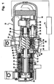
- FIG. 1 An embodiment of a screw compressor according to the invention, shown in Fig. 1 comprises a designated as a whole with 10 housing, which an engine-side section 12, a compressor section 14 and a pressure-side section 16 has.
- stator 22 fixed in the motor side Section 12 of the housing 10 is seated and its rotor 24 about an axis 26th is rotatably supported within the stator 22.
- the rotor 24 drives a drive shaft 28, via which a pair cooperating screw rotor 30 are rotationally driven, wherein the A pair of screw rotors 30 in screw rotor bores 32 of a Whole with 34 designated compressor screw housing sitting, in turn is disposed in the compressor section 14 of the housing 10.
- bearing seats 36 and 38 provided in the outer housing 10, in which of the screw rotors 30th outgoing shaft pieces 40 and 42 by means of rotary bearings 44 and 46 rotatable are stored.
- the bearing receivers 36 and 38 and the compressor screw housing 34 in one piece to the housing 10 in the region of the compressor section 14 molded.
- a slide bore 48 is provided, in which a spool 50 in a direction parallel to the axis 26 extending displacement direction 52 is movable, wherein the spool 50 via a coupling rod 54 with an adjusting 56th is coupled, which, for example, a control cylinder 58 and a control piston 60 formed by pressurized media within the Adjusting cylinder 58 is displaceable, so that via the coupling rod 54th coupled spool 50 corresponding to the positions of the actuator piston 60 is also displaceable.
- the spool 50 has one of an inlet side 62 of the compressor screw housing 64 facing control edge 64 through which Moving towards an outlet 66 of the compressor screw housing 34 controlled compression ratio can be reduced.
- the control of the adjusting device 56 via a 70 as a whole designated control of the screw compressor, where for an exact Control a position of the spool 50 must be detectable.
- the spool 50 is associated with a web carrier 72, which is coupled to the spool 50 in the direction of the displacement direction 52 is displaceable and which has a track 74 through a track follower 76 is scanned.
- the web 74 is preferably provided as on the web support 72 rectilinear scanning surface 78 is formed, which is inclined to the Displacement 52 extends and preferably extends so that at maximum displacement of the spool 50 from the one maximum Compression ratio corresponding position to a minimum Compression ratio corresponding position the track follower 76 in his transverse to the displacement direction 52, preferably approximately perpendicular to this, extending movement direction 80 shifts by a maximum distance, the less than the maximum travel of the spool 50 with the web carrier 72 in the direction of displacement 52nd
- the track follower 76 through the head of a stylus 82 of a Displacer 84 formed, the path of the track follower 76 in the direction of movement 80 receives and transmits to the controller 70, each individual Position of the track follower 76 in the direction of movement 80 a unique Position of the spool 50 is assigned in the displacement direction 52, so that the respective position of the spool 50 exactly with the encoder 84 can detect.
- the web support 72 is preferably at one over the control edge 64 in the direction of displacement 52 addition extending guide member 86 of the spool 50, in continuation but within a maximum cross section of the Control slide 50 held so that the web carrier 72 in the direction of Axis 26 seen approximately in the area between the electric motor 20 and the compressor screw housing 34 lying bearing receptacle 36, and indeed in a surrounding inner space 88 of the outer housing 10, which around the bearing receptacle 36 around to the inlet side 62 of the Compressor screw housing 34 and also in the direction of the electric motor 20th extends.
- the spool 50 By the arrangement of the web carrier 72 within the maximum Cross-sectional shape of the spool 50 and in particular within a Cross-sectional shape of the guide member 86 is the spool 50 with the mounted web support 72 from the side of the outlet 66 in the slide bore 48 inserted and pushed through them to the interior 88.
- the interior 88 is preferably at the pressure of the inflowing Refrigerant in the region of the inlet side 62nd
- the displacement sensor 84 is preferably located on an outer side of the compressor section 14 of the housing 10 and passes through the stylus 82 a Housing 10 passing through hole 90 to spring loaded with the track follower 76 to be able to rest on the web 74.
Landscapes
- Engineering & Computer Science (AREA)
- Mechanical Engineering (AREA)
- General Engineering & Computer Science (AREA)
- Applications Or Details Of Rotary Compressors (AREA)
Applications Claiming Priority (2)
| Application Number | Priority Date | Filing Date | Title |
|---|---|---|---|
| DE10333400 | 2003-07-16 | ||
| DE10333400A DE10333400A1 (de) | 2003-07-16 | 2003-07-16 | Schraubenverdichter |
Publications (1)
| Publication Number | Publication Date |
|---|---|
| EP1498611A1 true EP1498611A1 (fr) | 2005-01-19 |
Family
ID=33462008
Family Applications (1)
| Application Number | Title | Priority Date | Filing Date |
|---|---|---|---|
| EP04012535A Withdrawn EP1498611A1 (fr) | 2003-07-16 | 2004-05-27 | Compresseur à vis |
Country Status (4)
| Country | Link |
|---|---|
| US (1) | US20050013702A1 (fr) |
| EP (1) | EP1498611A1 (fr) |
| CN (1) | CN1576588A (fr) |
| DE (1) | DE10333400A1 (fr) |
Cited By (3)
| Publication number | Priority date | Publication date | Assignee | Title |
|---|---|---|---|---|
| WO2016055412A1 (fr) * | 2014-10-08 | 2016-04-14 | Bitzer Kühlmaschinenbau Gmbh | Compresseur à vis |
| WO2017174131A1 (fr) * | 2016-04-06 | 2017-10-12 | Bitzer Kühlmaschinenbau Gmbh | Unité compresseur et son procédé de fonctionnement |
| US10941770B2 (en) | 2010-07-20 | 2021-03-09 | Trane International Inc. | Variable capacity screw compressor and method |
Families Citing this family (4)
| Publication number | Priority date | Publication date | Assignee | Title |
|---|---|---|---|---|
| CN102748286A (zh) * | 2012-04-11 | 2012-10-24 | 无锡市制冷设备厂有限责任公司 | 一种螺杆压缩机 |
| DE102013020534A1 (de) | 2013-12-12 | 2015-06-18 | Gea Refrigeration Germany Gmbh | Verdichter |
| DE102014010534A1 (de) * | 2014-07-19 | 2016-01-21 | Gea Refrigeration Germany Gmbh | Schraubenverdichter |
| DE102015006129A1 (de) * | 2015-05-09 | 2016-11-10 | Man Diesel & Turbo Se | Schraubenmaschine |
Citations (6)
| Publication number | Priority date | Publication date | Assignee | Title |
|---|---|---|---|---|
| US4536130A (en) * | 1984-06-18 | 1985-08-20 | Dunham-Bush, Inc. | Simplified unloader indicator for helical screw rotary compressor |
| US4548549A (en) * | 1982-09-10 | 1985-10-22 | Frick Company | Micro-processor control of compression ratio at full load in a helical screw rotary compressor responsive to compressor drive motor current |
| US4610612A (en) * | 1985-06-03 | 1986-09-09 | Vilter Manufacturing Corporation | Rotary screw gas compressor having dual slide valves |
| US5257921A (en) * | 1992-05-19 | 1993-11-02 | Fes, Inc. | Electronic slide valve position indicator |
| JPH09158867A (ja) * | 1995-12-06 | 1997-06-17 | Hitachi Ltd | スクリュー圧縮機の容量検知装置 |
| GB2331574A (en) * | 1997-11-20 | 1999-05-26 | Gethin Bermingham | Sensing device for screw compressor valve |
Family Cites Families (2)
| Publication number | Priority date | Publication date | Assignee | Title |
|---|---|---|---|---|
| US4351160A (en) * | 1980-06-16 | 1982-09-28 | Borg-Warner Corporation | Capacity control systems for screw compressor based water chillers |
| US4609329A (en) * | 1985-04-05 | 1986-09-02 | Frick Company | Micro-processor control of a movable slide stop and a movable slide valve in a helical screw rotary compressor with an enconomizer inlet port |
-
2003
- 2003-07-16 DE DE10333400A patent/DE10333400A1/de not_active Ceased
-
2004
- 2004-05-27 EP EP04012535A patent/EP1498611A1/fr not_active Withdrawn
- 2004-07-02 US US10/884,421 patent/US20050013702A1/en not_active Abandoned
- 2004-07-15 CN CN200410071636.1A patent/CN1576588A/zh active Pending
Patent Citations (6)
| Publication number | Priority date | Publication date | Assignee | Title |
|---|---|---|---|---|
| US4548549A (en) * | 1982-09-10 | 1985-10-22 | Frick Company | Micro-processor control of compression ratio at full load in a helical screw rotary compressor responsive to compressor drive motor current |
| US4536130A (en) * | 1984-06-18 | 1985-08-20 | Dunham-Bush, Inc. | Simplified unloader indicator for helical screw rotary compressor |
| US4610612A (en) * | 1985-06-03 | 1986-09-09 | Vilter Manufacturing Corporation | Rotary screw gas compressor having dual slide valves |
| US5257921A (en) * | 1992-05-19 | 1993-11-02 | Fes, Inc. | Electronic slide valve position indicator |
| JPH09158867A (ja) * | 1995-12-06 | 1997-06-17 | Hitachi Ltd | スクリュー圧縮機の容量検知装置 |
| GB2331574A (en) * | 1997-11-20 | 1999-05-26 | Gethin Bermingham | Sensing device for screw compressor valve |
Non-Patent Citations (1)
| Title |
|---|
| PATENT ABSTRACTS OF JAPAN vol. 1997, no. 10 31 October 1997 (1997-10-31) * |
Cited By (13)
| Publication number | Priority date | Publication date | Assignee | Title |
|---|---|---|---|---|
| US11486396B2 (en) | 2010-07-20 | 2022-11-01 | Trane International Inc. | Variable capacity screw compressor and method |
| US10941770B2 (en) | 2010-07-20 | 2021-03-09 | Trane International Inc. | Variable capacity screw compressor and method |
| US11022117B2 (en) | 2010-07-20 | 2021-06-01 | Trane International Inc. | Variable capacity screw compressor and method |
| US11933301B2 (en) | 2010-07-20 | 2024-03-19 | Trane International Inc. | Variable capacity screw compressor and method |
| RU2684053C2 (ru) * | 2014-10-08 | 2019-04-03 | Битцер Кюльмашиненбау Гмбх | Винтовой компрессор (варианты) |
| US10794382B2 (en) | 2014-10-08 | 2020-10-06 | Bitzer Kuehlmaschinebau GmbH | Screw compressor with control slider and detector |
| WO2016055412A1 (fr) * | 2014-10-08 | 2016-04-14 | Bitzer Kühlmaschinenbau Gmbh | Compresseur à vis |
| WO2017174131A1 (fr) * | 2016-04-06 | 2017-10-12 | Bitzer Kühlmaschinenbau Gmbh | Unité compresseur et son procédé de fonctionnement |
| CN109072914A (zh) * | 2016-04-06 | 2018-12-21 | 比泽尔制冷设备有限公司 | 压缩机单元和用于运行压缩机单元的方法 |
| RU2729967C2 (ru) * | 2016-04-06 | 2020-08-13 | Битцер Кюльмашиненбау Гмбх | Компрессорный модуль и способ эксплуатации компрессорного модуля |
| US11460026B2 (en) | 2016-04-06 | 2022-10-04 | Bitzer Kuehlmaschinenbau Gmbh | Compressor unit and method for operating a compressor unit |
| EP4245997A3 (fr) * | 2016-04-06 | 2023-12-27 | BITZER Kühlmaschinenbau GmbH | Unité de compresseur et procédé de fonctionnement d'une unité de compresseur |
| CN109072914B (zh) * | 2016-04-06 | 2025-02-14 | 比泽尔制冷设备有限公司 | 压缩机单元和用于运行压缩机单元的方法 |
Also Published As
| Publication number | Publication date |
|---|---|
| CN1576588A (zh) | 2005-02-09 |
| DE10333400A1 (de) | 2005-02-10 |
| US20050013702A1 (en) | 2005-01-20 |
Similar Documents
| Publication | Publication Date | Title |
|---|---|---|
| DE69412869T2 (de) | Kompressor | |
| EP3204648B1 (fr) | Compresseur à vis | |
| EP0378967B1 (fr) | Compresseur à piston | |
| EP4245997B1 (fr) | Unité de compresseur et procédé de fonctionnement d'une unité de compresseur | |
| DE69506778T3 (de) | Antriebsgerät mit Schlittentisch | |
| EP1498611A1 (fr) | Compresseur à vis | |
| DE68903695T2 (de) | Tiefsttemperaturkaeltemaschinen. | |
| CH678881A5 (fr) | ||
| EP2577062B1 (fr) | Dispositif de pompage à piston | |
| DE3740810A1 (de) | Kryogener kompressor | |
| DE102006016791B4 (de) | Vakuumpumpe | |
| DE102004060596A1 (de) | Schraubenverdichter | |
| DE3633644A1 (de) | Kompressor mit variabler foerderleistung | |
| EP1831565B1 (fr) | Compresseur pour un appareil frigorifique | |
| EP2176519B1 (fr) | Pompe à vide à palette coulissante | |
| EP0124727A2 (fr) | Cylindre de travail | |
| DE4320963C2 (de) | Schmiermittelfreie Vakuum-Pumpeneinrichtung | |
| JPS62153581A (ja) | 往復動圧縮機 | |
| EP0645544B1 (fr) | Système de motorisation et de guidage pour mouvoir une charge | |
| WO2026002970A1 (fr) | Compresseur à piston oscillant | |
| DE10248338A1 (de) | Tauchkolbenpumpe | |
| EP2918835A1 (fr) | Pompe à membrane | |
| DE3014024A1 (de) | Trockenlauf-verdichter, insbesondere hubkolbenverdichter zur foerderung kompressibler medien | |
| AT8188U1 (de) | Kältemittelverdichter | |
| DE3006819A1 (de) | Fluidische zentralverriegelungsanlage |
Legal Events
| Date | Code | Title | Description |
|---|---|---|---|
| PUAI | Public reference made under article 153(3) epc to a published international application that has entered the european phase |
Free format text: ORIGINAL CODE: 0009012 |
|
| AK | Designated contracting states |
Kind code of ref document: A1 Designated state(s): AT BE BG CH CY CZ DE DK EE ES FI FR GB GR HU IE IT LI LU MC NL PL PT RO SE SI SK TR |
|
| AX | Request for extension of the european patent |
Extension state: AL HR LT LV MK |
|
| AKX | Designation fees paid | ||
| REG | Reference to a national code |
Ref country code: DE Ref legal event code: 8566 |
|
| STAA | Information on the status of an ep patent application or granted ep patent |
Free format text: STATUS: THE APPLICATION IS DEEMED TO BE WITHDRAWN |
|
| 18D | Application deemed to be withdrawn |
Effective date: 20050720 |