EP1498631B1 - Procede de regulation du decalage du signal de detection de courant dans un controleur de transmission d'une puissance d'entrainement - Google Patents
Procede de regulation du decalage du signal de detection de courant dans un controleur de transmission d'une puissance d'entrainement Download PDFInfo
- Publication number
- EP1498631B1 EP1498631B1 EP03723203A EP03723203A EP1498631B1 EP 1498631 B1 EP1498631 B1 EP 1498631B1 EP 03723203 A EP03723203 A EP 03723203A EP 03723203 A EP03723203 A EP 03723203A EP 1498631 B1 EP1498631 B1 EP 1498631B1
- Authority
- EP
- European Patent Office
- Prior art keywords
- drive power
- detection signal
- current detection
- power transmission
- current
- Prior art date
- Legal status (The legal status is an assumption and is not a legal conclusion. Google has not performed a legal analysis and makes no representation as to the accuracy of the status listed.)
- Expired - Lifetime
Links
- 238000001514 detection method Methods 0.000 title claims abstract description 61
- 238000000034 method Methods 0.000 title claims abstract description 12
- 230000005540 biological transmission Effects 0.000 title claims description 54
- 230000005284 excitation Effects 0.000 description 24
- 238000010586 diagram Methods 0.000 description 3
- 239000000696 magnetic material Substances 0.000 description 3
- 239000003990 capacitor Substances 0.000 description 2
- 230000003321 amplification Effects 0.000 description 1
- 238000006243 chemical reaction Methods 0.000 description 1
- 238000002485 combustion reaction Methods 0.000 description 1
- 230000000694 effects Effects 0.000 description 1
- 230000005611 electricity Effects 0.000 description 1
- 230000004907 flux Effects 0.000 description 1
- 230000010354 integration Effects 0.000 description 1
- 230000005389 magnetism Effects 0.000 description 1
- 238000013507 mapping Methods 0.000 description 1
- 238000003199 nucleic acid amplification method Methods 0.000 description 1
- 239000004065 semiconductor Substances 0.000 description 1
- 230000001629 suppression Effects 0.000 description 1
Images



Classifications
-
- F—MECHANICAL ENGINEERING; LIGHTING; HEATING; WEAPONS; BLASTING
- F16—ENGINEERING ELEMENTS AND UNITS; GENERAL MEASURES FOR PRODUCING AND MAINTAINING EFFECTIVE FUNCTIONING OF MACHINES OR INSTALLATIONS; THERMAL INSULATION IN GENERAL
- F16H—GEARING
- F16H61/00—Control functions within control units of change-speed- or reversing-gearings for conveying rotary motion ; Control of exclusively fluid gearing, friction gearing, gearings with endless flexible members or other particular types of gearing
- F16H61/02—Control functions within control units of change-speed- or reversing-gearings for conveying rotary motion ; Control of exclusively fluid gearing, friction gearing, gearings with endless flexible members or other particular types of gearing characterised by the signals used
- F16H61/0202—Control functions within control units of change-speed- or reversing-gearings for conveying rotary motion ; Control of exclusively fluid gearing, friction gearing, gearings with endless flexible members or other particular types of gearing characterised by the signals used the signals being electric
- F16H61/0251—Elements specially adapted for electric control units, e.g. valves for converting electrical signals to fluid signals
-
- B—PERFORMING OPERATIONS; TRANSPORTING
- B60—VEHICLES IN GENERAL
- B60W—CONJOINT CONTROL OF VEHICLE SUB-UNITS OF DIFFERENT TYPE OR DIFFERENT FUNCTION; CONTROL SYSTEMS SPECIALLY ADAPTED FOR HYBRID VEHICLES; ROAD VEHICLE DRIVE CONTROL SYSTEMS FOR PURPOSES NOT RELATED TO THE CONTROL OF A PARTICULAR SUB-UNIT
- B60W30/00—Purposes of road vehicle drive control systems not related to the control of a particular sub-unit, e.g. of systems using conjoint control of vehicle sub-units
- B60W30/18—Propelling the vehicle
- B60W30/18009—Propelling the vehicle related to particular drive situations
- B60W30/18054—Propelling the vehicle related to particular drive situations at stand still, e.g. engine in idling state
-
- F—MECHANICAL ENGINEERING; LIGHTING; HEATING; WEAPONS; BLASTING
- F16—ENGINEERING ELEMENTS AND UNITS; GENERAL MEASURES FOR PRODUCING AND MAINTAINING EFFECTIVE FUNCTIONING OF MACHINES OR INSTALLATIONS; THERMAL INSULATION IN GENERAL
- F16D—COUPLINGS FOR TRANSMITTING ROTATION; CLUTCHES; BRAKES
- F16D27/00—Magnetically- or electrically- actuated clutches; Control or electric circuits therefor
- F16D27/10—Magnetically- or electrically- actuated clutches; Control or electric circuits therefor with an electromagnet not rotating with a clutching member, i.e. without collecting rings
-
- F—MECHANICAL ENGINEERING; LIGHTING; HEATING; WEAPONS; BLASTING
- F16—ENGINEERING ELEMENTS AND UNITS; GENERAL MEASURES FOR PRODUCING AND MAINTAINING EFFECTIVE FUNCTIONING OF MACHINES OR INSTALLATIONS; THERMAL INSULATION IN GENERAL
- F16D—COUPLINGS FOR TRANSMITTING ROTATION; CLUTCHES; BRAKES
- F16D48/00—External control of clutches
- F16D48/06—Control by electric or electronic means, e.g. of fluid pressure
- F16D48/064—Control of electrically or electromagnetically actuated clutches
-
- B—PERFORMING OPERATIONS; TRANSPORTING
- B60—VEHICLES IN GENERAL
- B60K—ARRANGEMENT OR MOUNTING OF PROPULSION UNITS OR OF TRANSMISSIONS IN VEHICLES; ARRANGEMENT OR MOUNTING OF PLURAL DIVERSE PRIME-MOVERS IN VEHICLES; AUXILIARY DRIVES FOR VEHICLES; INSTRUMENTATION OR DASHBOARDS FOR VEHICLES; ARRANGEMENTS IN CONNECTION WITH COOLING, AIR INTAKE, GAS EXHAUST OR FUEL SUPPLY OF PROPULSION UNITS IN VEHICLES
- B60K23/00—Arrangement or mounting of control devices for vehicle transmissions, or parts thereof, not otherwise provided for
- B60K23/08—Arrangement or mounting of control devices for vehicle transmissions, or parts thereof, not otherwise provided for for changing number of driven wheels, for switching from driving one axle to driving two or more axles
- B60K23/0808—Arrangement or mounting of control devices for vehicle transmissions, or parts thereof, not otherwise provided for for changing number of driven wheels, for switching from driving one axle to driving two or more axles for varying torque distribution between driven axles, e.g. by transfer clutch
-
- F—MECHANICAL ENGINEERING; LIGHTING; HEATING; WEAPONS; BLASTING
- F16—ENGINEERING ELEMENTS AND UNITS; GENERAL MEASURES FOR PRODUCING AND MAINTAINING EFFECTIVE FUNCTIONING OF MACHINES OR INSTALLATIONS; THERMAL INSULATION IN GENERAL
- F16D—COUPLINGS FOR TRANSMITTING ROTATION; CLUTCHES; BRAKES
- F16D27/00—Magnetically- or electrically- actuated clutches; Control or electric circuits therefor
- F16D2027/002—Electric or electronic circuits relating to actuation of electromagnetic clutches
-
- F—MECHANICAL ENGINEERING; LIGHTING; HEATING; WEAPONS; BLASTING
- F16—ENGINEERING ELEMENTS AND UNITS; GENERAL MEASURES FOR PRODUCING AND MAINTAINING EFFECTIVE FUNCTIONING OF MACHINES OR INSTALLATIONS; THERMAL INSULATION IN GENERAL
- F16D—COUPLINGS FOR TRANSMITTING ROTATION; CLUTCHES; BRAKES
- F16D2500/00—External control of clutches by electric or electronic means
- F16D2500/10—System to be controlled
- F16D2500/102—Actuator
- F16D2500/1021—Electrical type
- F16D2500/1022—Electromagnet
-
- F—MECHANICAL ENGINEERING; LIGHTING; HEATING; WEAPONS; BLASTING
- F16—ENGINEERING ELEMENTS AND UNITS; GENERAL MEASURES FOR PRODUCING AND MAINTAINING EFFECTIVE FUNCTIONING OF MACHINES OR INSTALLATIONS; THERMAL INSULATION IN GENERAL
- F16D—COUPLINGS FOR TRANSMITTING ROTATION; CLUTCHES; BRAKES
- F16D2500/00—External control of clutches by electric or electronic means
- F16D2500/10—System to be controlled
- F16D2500/104—Clutch
- F16D2500/10406—Clutch position
- F16D2500/10412—Transmission line of a vehicle
-
- F—MECHANICAL ENGINEERING; LIGHTING; HEATING; WEAPONS; BLASTING
- F16—ENGINEERING ELEMENTS AND UNITS; GENERAL MEASURES FOR PRODUCING AND MAINTAINING EFFECTIVE FUNCTIONING OF MACHINES OR INSTALLATIONS; THERMAL INSULATION IN GENERAL
- F16D—COUPLINGS FOR TRANSMITTING ROTATION; CLUTCHES; BRAKES
- F16D2500/00—External control of clutches by electric or electronic means
- F16D2500/10—System to be controlled
- F16D2500/104—Clutch
- F16D2500/10443—Clutch type
- F16D2500/1045—Friction clutch
-
- F—MECHANICAL ENGINEERING; LIGHTING; HEATING; WEAPONS; BLASTING
- F16—ENGINEERING ELEMENTS AND UNITS; GENERAL MEASURES FOR PRODUCING AND MAINTAINING EFFECTIVE FUNCTIONING OF MACHINES OR INSTALLATIONS; THERMAL INSULATION IN GENERAL
- F16D—COUPLINGS FOR TRANSMITTING ROTATION; CLUTCHES; BRAKES
- F16D2500/00—External control of clutches by electric or electronic means
- F16D2500/30—Signal inputs
- F16D2500/302—Signal inputs from the actuator
- F16D2500/3022—Current
-
- F—MECHANICAL ENGINEERING; LIGHTING; HEATING; WEAPONS; BLASTING
- F16—ENGINEERING ELEMENTS AND UNITS; GENERAL MEASURES FOR PRODUCING AND MAINTAINING EFFECTIVE FUNCTIONING OF MACHINES OR INSTALLATIONS; THERMAL INSULATION IN GENERAL
- F16D—COUPLINGS FOR TRANSMITTING ROTATION; CLUTCHES; BRAKES
- F16D2500/00—External control of clutches by electric or electronic means
- F16D2500/30—Signal inputs
- F16D2500/306—Signal inputs from the engine
- F16D2500/3063—Engine fuel flow rate
-
- F—MECHANICAL ENGINEERING; LIGHTING; HEATING; WEAPONS; BLASTING
- F16—ENGINEERING ELEMENTS AND UNITS; GENERAL MEASURES FOR PRODUCING AND MAINTAINING EFFECTIVE FUNCTIONING OF MACHINES OR INSTALLATIONS; THERMAL INSULATION IN GENERAL
- F16D—COUPLINGS FOR TRANSMITTING ROTATION; CLUTCHES; BRAKES
- F16D2500/00—External control of clutches by electric or electronic means
- F16D2500/30—Signal inputs
- F16D2500/31—Signal inputs from the vehicle
- F16D2500/3108—Vehicle speed
- F16D2500/3111—Standing still, i.e. signal detecting when the vehicle is standing still or bellow a certain limit speed
-
- F—MECHANICAL ENGINEERING; LIGHTING; HEATING; WEAPONS; BLASTING
- F16—ENGINEERING ELEMENTS AND UNITS; GENERAL MEASURES FOR PRODUCING AND MAINTAINING EFFECTIVE FUNCTIONING OF MACHINES OR INSTALLATIONS; THERMAL INSULATION IN GENERAL
- F16D—COUPLINGS FOR TRANSMITTING ROTATION; CLUTCHES; BRAKES
- F16D2500/00—External control of clutches by electric or electronic means
- F16D2500/30—Signal inputs
- F16D2500/31—Signal inputs from the vehicle
- F16D2500/3114—Vehicle wheels
- F16D2500/3115—Vehicle wheel speed
-
- F—MECHANICAL ENGINEERING; LIGHTING; HEATING; WEAPONS; BLASTING
- F16—ENGINEERING ELEMENTS AND UNITS; GENERAL MEASURES FOR PRODUCING AND MAINTAINING EFFECTIVE FUNCTIONING OF MACHINES OR INSTALLATIONS; THERMAL INSULATION IN GENERAL
- F16D—COUPLINGS FOR TRANSMITTING ROTATION; CLUTCHES; BRAKES
- F16D2500/00—External control of clutches by electric or electronic means
- F16D2500/30—Signal inputs
- F16D2500/314—Signal inputs from the user
- F16D2500/31406—Signal inputs from the user input from pedals
- F16D2500/3144—Accelerator pedal position
-
- F—MECHANICAL ENGINEERING; LIGHTING; HEATING; WEAPONS; BLASTING
- F16—ENGINEERING ELEMENTS AND UNITS; GENERAL MEASURES FOR PRODUCING AND MAINTAINING EFFECTIVE FUNCTIONING OF MACHINES OR INSTALLATIONS; THERMAL INSULATION IN GENERAL
- F16D—COUPLINGS FOR TRANSMITTING ROTATION; CLUTCHES; BRAKES
- F16D2500/00—External control of clutches by electric or electronic means
- F16D2500/30—Signal inputs
- F16D2500/316—Other signal inputs not covered by the groups above
- F16D2500/3166—Detection of an elapsed period of time
-
- F—MECHANICAL ENGINEERING; LIGHTING; HEATING; WEAPONS; BLASTING
- F16—ENGINEERING ELEMENTS AND UNITS; GENERAL MEASURES FOR PRODUCING AND MAINTAINING EFFECTIVE FUNCTIONING OF MACHINES OR INSTALLATIONS; THERMAL INSULATION IN GENERAL
- F16D—COUPLINGS FOR TRANSMITTING ROTATION; CLUTCHES; BRAKES
- F16D2500/00—External control of clutches by electric or electronic means
- F16D2500/50—Problem to be solved by the control system
- F16D2500/501—Relating the actuator
- F16D2500/5018—Calibration or recalibration of the actuator
-
- F—MECHANICAL ENGINEERING; LIGHTING; HEATING; WEAPONS; BLASTING
- F16—ENGINEERING ELEMENTS AND UNITS; GENERAL MEASURES FOR PRODUCING AND MAINTAINING EFFECTIVE FUNCTIONING OF MACHINES OR INSTALLATIONS; THERMAL INSULATION IN GENERAL
- F16D—COUPLINGS FOR TRANSMITTING ROTATION; CLUTCHES; BRAKES
- F16D2500/00—External control of clutches by electric or electronic means
- F16D2500/70—Details about the implementation of the control system
- F16D2500/704—Output parameters from the control unit; Target parameters to be controlled
- F16D2500/70402—Actuator parameters
- F16D2500/70418—Current
-
- F—MECHANICAL ENGINEERING; LIGHTING; HEATING; WEAPONS; BLASTING
- F16—ENGINEERING ELEMENTS AND UNITS; GENERAL MEASURES FOR PRODUCING AND MAINTAINING EFFECTIVE FUNCTIONING OF MACHINES OR INSTALLATIONS; THERMAL INSULATION IN GENERAL
- F16D—COUPLINGS FOR TRANSMITTING ROTATION; CLUTCHES; BRAKES
- F16D2500/00—External control of clutches by electric or electronic means
- F16D2500/70—Details about the implementation of the control system
- F16D2500/704—Output parameters from the control unit; Target parameters to be controlled
- F16D2500/70422—Clutch parameters
- F16D2500/70438—From the output shaft
- F16D2500/7044—Output shaft torque
-
- F—MECHANICAL ENGINEERING; LIGHTING; HEATING; WEAPONS; BLASTING
- F16—ENGINEERING ELEMENTS AND UNITS; GENERAL MEASURES FOR PRODUCING AND MAINTAINING EFFECTIVE FUNCTIONING OF MACHINES OR INSTALLATIONS; THERMAL INSULATION IN GENERAL
- F16D—COUPLINGS FOR TRANSMITTING ROTATION; CLUTCHES; BRAKES
- F16D2500/00—External control of clutches by electric or electronic means
- F16D2500/70—Details about the implementation of the control system
- F16D2500/706—Strategy of control
- F16D2500/7061—Feed-back
- F16D2500/70615—PI control
-
- F—MECHANICAL ENGINEERING; LIGHTING; HEATING; WEAPONS; BLASTING
- F16—ENGINEERING ELEMENTS AND UNITS; GENERAL MEASURES FOR PRODUCING AND MAINTAINING EFFECTIVE FUNCTIONING OF MACHINES OR INSTALLATIONS; THERMAL INSULATION IN GENERAL
- F16H—GEARING
- F16H2342/00—Calibrating
- F16H2342/10—Calibrating valves
Definitions
- the present invention relates to an offset adjusting method for a current detection signal in a drive power transmission control apparatus.
- the drive power transmission control apparatus for vehicles, there are types in which the drive power transmission amount is controlled by duty-controlling an electromagnet in an "electromagnetic clutch" as disclosed in Japanese Utility Model No. HEI6-16731 or "drive power transmission control apparatus” as disclosed in an applied specification of JP No. 2001-003937 A .
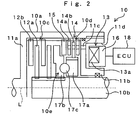
- magnetic force for attracting an armature to the electromagnet is generated by supplying excitation current duty-controlled to an electromagnetic coil of the electromagnet, so that the armature is attracted to the side of a friction clutch. Consequently, the clutch is engaged with a pressure corresponding to the magnitude of the magnetic force so as to transmit the drive power. That is, torque to be transmitted to the front wheels and rear wheels of a vehicle is divided depending on a current value of the excitation current to be supplied to the electromagnetic coil of the electromagnet.
- the excitation current to be supplied to the electromagnetic coil is detected by a current detection circuit for detecting that excitation current and inputted to the electronic control unit (ECU) of the drive power transmission control apparatus as a current detection signal.
- ECU electronice control unit
- a control loop in which the input of the current detection signal is negative fed-back is constructed.
- the excitation current following a current instruction value determined by the ECU can be supplied to the electromagnetic coil of the electromagnet.
- the current detection signal to be outputted from the current detection circuit is generally outputted through an operational amplifier after it is converted to a voltage signal.
- a configuration in which the voltage from an amplifying circuit is outputted as an offset voltage when no current is supplied to the electromagnetic coil of the electromagnet, that is, the value of the excitation current is 0A (zero ampere) is often adopted.
- the output voltage by the current detection signal when the excitation current is 0A is always deflected due to changes in the ambient temperature of the current detection circuit, deviation of the electric characteristic of component part and the like.
- Document JP 2000110855 discloses a method for calibrating an electro-magnetic clutch during creep operations of the vehicle.
- the present invention has been achieved to solve the above-described problem and an object of the present invention is to provide an offset adjustment method for a current detection signal in the drive power transmission control apparatus capable of controlling the torque distribution precisely.
- an offset adjusting method for a current detection signal in a drive power transmission control apparatus for controlling a transmission amount of drive power by the a drive power transmission apparatus by controlling a current is comprising:
- an offset adjusting method for a current detection signal in a drive power transmission control apparatus for controlling the transmission amount of a drive power by a drive power transmission apparatus based on a current detection signal outputted from a circuit for detecting a current, is comprising:
- the offset value can be set taking that matter into account, thereby preventing generation of an error which may occur in a current detection signal due to a temperature drift. Therefore, control accuracy performance is improved, so that torque distribution can be controlled at a high accuracy.
- the offset adjusting method for a current detection signal in a drive power transmission control apparatus according to claim 1 or claim 2 wherein said third step is carried out after a predetermined period passes since the value of said current detection signal is set to the offset value last.
- a processing for determining whether or not the opening degree of the throttle valve is substantially 0% instead of a throttle opening degree signal m is read through the throttle valve opening degree sensor 2 instead of the accelerator pressing amount sensor 9 shown in FIG. 1 so as to determine whether or not the opening degree of the throttle valve is substantially 0%, that is, whether or not the accelerator pedal is pressed by a vehicle driver. If it can be determined that the opening degree of the throttle valve is substantially 0% in step S105 (Yes in S105), it means that the vehicle is stopped or its engine is stopped or idled.
- step S107 if such determination is impossible (No in S105), it means that the engine is being driven beyond its idling state even if the vehicle is stopped.
- step S103 As described above, the same operation and effect can be exerted even if the content of the processing by step S105 is replaced.
- step S113 is executed if the second timer value exceeds the predetermined value Tb (Yes in step S111), the setting of the offset voltage value Vof in step S113 is never executed even if the conditions for step S101 and step S105 are established until the second timer value reaches the predetermined value Tb. Consequently, generation of such an unstable condition of the offset value Vof that the set offset value Vof is reset repeatedly in a short period can be prevented. Therefore, the torque distribution can be controlled at a high precision under a stable control performance.
Landscapes
- Engineering & Computer Science (AREA)
- General Engineering & Computer Science (AREA)
- Mechanical Engineering (AREA)
- Physics & Mathematics (AREA)
- Electromagnetism (AREA)
- Fluid Mechanics (AREA)
- Automation & Control Theory (AREA)
- Transportation (AREA)
- Arrangement And Driving Of Transmission Devices (AREA)
- Hydraulic Clutches, Magnetic Clutches, Fluid Clutches, And Fluid Joints (AREA)
- Control Of Transmission Device (AREA)
Abstract
Claims (3)
- Procédé de réglage de décalage d'un signal de détection de courant dans un dispositif de commande de transmission de puissance d'entraînement pour commander une quantité de transmission de puissance d'entraînement par le dispositif de transmission de puissance d'entraînement en commandant un courant, caractérisé en ce qu'il comprend en outre :une première étape de détermination de si ou non toutes les vitesses de roue des roues de véhicule sont de 0 km/h ;une seconde étape de détermination de si ou non la quantité de pression de la pédale d'accélérateur est de 0% ; etune troisième étape, s'il est déterminé que toutes les vitesses de roue sont de 0 km/h lors de ladite première étape et que la quantité de pression de la pédale d'accélérateur est de 0% lors de la seconde étape, consistant à régler la valeur dudit signal de détection de courant à ce moment à une valeur décalée.
- Procédé de réglage de décalage d'un signal de détection de courant dans un dispositif de commande de transmission de puissance d'entraînement pour commander la quantité de transmission de puissance d'entraînement par un dispositif de transmission de puissance d'entraînement en fonction d'un signal de détection de courant sorti d'un circuit pour détecter un courant, caractérisé en ce qu'il comprend en outre :une première étape de détermination de si ou non toutes les vitesses de roue des roues de véhicule sont de 0 km/h ;une seconde étape de détermination de si ou non le degré d'ouverture d'un papillon d'admission est sensiblement de 0% ; etune troisième étape, s'il est déterminé que toutes les vitesses de roue sont de 0 km/h lors de ladite première étape et que le degré d'ouverture du papillon d'admission est sensiblement de 0% lors de ladite seconde étape, consistant à régler la valeur dudit signal de détection de courant à ce moment à une valeur décalée.
- Procédé de réglage de décalage pour un signal de détection de courant dans un dispositif de commande de transmission de puissance d'entraînement selon la revendication 1 ou la revendication 2 dans lequel ladite troisième étape est réalisée après qu'une période prédéterminée a passé depuis que la valeur dudit signal de détection de courant a été réglée pour la dernière fois à la valeur décalée.
Applications Claiming Priority (3)
| Application Number | Priority Date | Filing Date | Title |
|---|---|---|---|
| JP2002123950 | 2002-04-25 | ||
| JP2002123950A JP3985579B2 (ja) | 2002-04-25 | 2002-04-25 | 駆動力伝達制御装置における電流検出信号のオフセット調整方法 |
| PCT/JP2003/005320 WO2003091590A1 (fr) | 2002-04-25 | 2003-04-25 | Procede de regulation du decalage du signal de detection de courant dans un controleur de transmission d'une puissance d'entrainement |
Publications (3)
| Publication Number | Publication Date |
|---|---|
| EP1498631A1 EP1498631A1 (fr) | 2005-01-19 |
| EP1498631A4 EP1498631A4 (fr) | 2009-09-09 |
| EP1498631B1 true EP1498631B1 (fr) | 2010-08-11 |
Family
ID=29267508
Family Applications (1)
| Application Number | Title | Priority Date | Filing Date |
|---|---|---|---|
| EP03723203A Expired - Lifetime EP1498631B1 (fr) | 2002-04-25 | 2003-04-25 | Procede de regulation du decalage du signal de detection de courant dans un controleur de transmission d'une puissance d'entrainement |
Country Status (5)
| Country | Link |
|---|---|
| US (1) | US7182712B2 (fr) |
| EP (1) | EP1498631B1 (fr) |
| JP (1) | JP3985579B2 (fr) |
| DE (1) | DE60333745D1 (fr) |
| WO (1) | WO2003091590A1 (fr) |
Families Citing this family (6)
| Publication number | Priority date | Publication date | Assignee | Title |
|---|---|---|---|---|
| DE10308497A1 (de) * | 2003-02-26 | 2004-09-09 | Robert Bosch Gmbh | Verfahren und Vorrichtung zur Detektion der Betätigung eines Bedienelementes |
| KR20080097189A (ko) * | 2006-03-07 | 2008-11-04 | 보그워너 인코포레이티드 | 트랙션을 최적화하기 위한 이차 차축의 선제 토크 제어 |
| DE102007055743A1 (de) * | 2007-12-10 | 2009-06-18 | Zf Friedrichshafen Ag | Verfahren zur Ermittlung des axialen Verschleißes und der Gegenkraftsteigung bei einem Lamellenschaltelement |
| DE102015113083B4 (de) * | 2015-08-07 | 2019-11-14 | Gkn Automotive Ltd. | Verfahren zum Auslösen eines Prüfungsprozesses bei einem Kupplungsaggregat, Kupplungsaggregat und Kraftfahrzeug |
| JP6874554B2 (ja) * | 2017-06-15 | 2021-05-19 | 株式会社ジェイテクト | 駆動力伝達装置の制御装置 |
| DE112021007741A5 (de) * | 2021-05-31 | 2024-04-11 | Gkn Automotive Ltd. | Verfahren zum Betrieb eines Antriebsstranges und Antriebsstrang |
Family Cites Families (13)
| Publication number | Priority date | Publication date | Assignee | Title |
|---|---|---|---|---|
| JPH0650133B2 (ja) * | 1983-12-27 | 1994-06-29 | 富士重工業株式会社 | 車両用電磁式クラツチのクラツチトルク制御装置 |
| JP2595209B2 (ja) | 1986-04-24 | 1997-04-02 | 富士重工業株式会社 | 車両用自動クラッチの制御装置 |
| JPH0314961A (ja) | 1989-06-12 | 1991-01-23 | Mazda Motor Corp | 変速機におけるトルク検出装置 |
| JPH0826911B2 (ja) | 1990-02-07 | 1996-03-21 | 三菱電機株式会社 | 自動車用電磁クラツチ電流制御装置 |
| JPH0616731U (ja) | 1992-08-04 | 1994-03-04 | 栃木富士産業株式会社 | 電磁クラッチ |
| JP2000110855A (ja) | 1998-09-30 | 2000-04-18 | Suzuki Motor Corp | クラッチのクリープ制御装置 |
| JP2000137040A (ja) | 1998-10-30 | 2000-05-16 | Kenwood Corp | 移動体の角速度検出装置、移動体の角度検出装置 |
| US6323496B1 (en) | 1999-04-19 | 2001-11-27 | Applied Materials, Inc. | Apparatus for reducing distortion in fluid bearing surfaces |
| JP3871849B2 (ja) * | 2000-04-03 | 2007-01-24 | 本田技研工業株式会社 | 電磁クラッチの故障判定装置 |
| JP2002031222A (ja) | 2000-07-11 | 2002-01-31 | Fuji Heavy Ind Ltd | 自動変速機の自動ニュートラル制御装置 |
| US6769526B2 (en) * | 2000-09-19 | 2004-08-03 | Nissan Motor Co., Ltd. | Apparatus for estimating clutch temperature |
| EP1415850A3 (fr) * | 2002-10-31 | 2006-05-10 | Toyoda Koki Kabushiki Kaisha | Dispositif de commande de distribution de couple pour véhicule à quatre roues motrices |
| US6834225B1 (en) * | 2004-02-09 | 2004-12-21 | Ford Global Technologies, Llc | Method and system for controlling a transfer case clutch to avoid wheel slip |
-
2002
- 2002-04-25 JP JP2002123950A patent/JP3985579B2/ja not_active Expired - Fee Related
-
2003
- 2003-04-25 WO PCT/JP2003/005320 patent/WO2003091590A1/fr not_active Ceased
- 2003-04-25 EP EP03723203A patent/EP1498631B1/fr not_active Expired - Lifetime
- 2003-04-25 US US10/490,117 patent/US7182712B2/en not_active Expired - Lifetime
- 2003-04-25 DE DE60333745T patent/DE60333745D1/de not_active Expired - Lifetime
Also Published As
| Publication number | Publication date |
|---|---|
| JP2003314586A (ja) | 2003-11-06 |
| WO2003091590A8 (fr) | 2005-03-10 |
| JP3985579B2 (ja) | 2007-10-03 |
| EP1498631A1 (fr) | 2005-01-19 |
| US20050148429A1 (en) | 2005-07-07 |
| EP1498631A4 (fr) | 2009-09-09 |
| DE60333745D1 (de) | 2010-09-23 |
| WO2003091590A1 (fr) | 2003-11-06 |
| US7182712B2 (en) | 2007-02-27 |
Similar Documents
| Publication | Publication Date | Title |
|---|---|---|
| EP1726851B1 (fr) | Différentiel blocable avec un capteur pour la position de l'élément de blocage | |
| US7101310B2 (en) | Model-based control for torque biasing system | |
| US6823252B2 (en) | Drive power distribution control method and device for four-wheel drive vehicle | |
| US4494641A (en) | Electromagnetic clutch control system for automobiles | |
| US7182712B2 (en) | Method for regulating offset of current detection signal in driving power transmission controller | |
| JP2004262321A (ja) | 4輪駆動車のトルク配分制御装置 | |
| CA1226923A (fr) | Regulateur de couple d'embrayage electromagnetique | |
| CN113071310B (zh) | 车辆控制装置和四轮驱动车辆 | |
| US6607061B2 (en) | Electromagnetic clutch control system | |
| JP3988405B2 (ja) | 駆動力伝達制御装置、プログラム、記録媒体 | |
| JP2004092570A (ja) | 駆動力伝達制御装置 | |
| US6543595B2 (en) | Driving force distribution device for vehicle | |
| JP4123887B2 (ja) | 車両用駆動力伝達装置の制御方法および制御装置 | |
| JP4042500B2 (ja) | 車両の運動制御装置の異常検出方法および駆動力伝達装置の異常検出方法 | |
| JP2020111237A (ja) | 駆動力伝達装置の制御装置 | |
| JP2002206566A (ja) | 駆動力伝達制御装置 | |
| JP3938287B2 (ja) | 駆動力伝達制御装置、プログラム、記録媒体 | |
| JP4674227B2 (ja) | カップリング | |
| JP3938288B2 (ja) | 駆動力伝達制御装置、プログラム、記録媒体 | |
| JPH02300581A (ja) | 油圧制御用電磁バルブ制御装置 | |
| JP3938291B2 (ja) | 駆動力伝達制御装置、プログラム、記録媒体 | |
| JPH11208303A (ja) | 車両用駆動力伝達装置 | |
| JP2005083464A (ja) | 四輪駆動装置 | |
| JP2001116813A (ja) | 磁束検出装置 | |
| JPS6350217B2 (fr) |
Legal Events
| Date | Code | Title | Description |
|---|---|---|---|
| PUAI | Public reference made under article 153(3) epc to a published international application that has entered the european phase |
Free format text: ORIGINAL CODE: 0009012 |
|
| 17P | Request for examination filed |
Effective date: 20040506 |
|
| AK | Designated contracting states |
Kind code of ref document: A1 Designated state(s): AT BE BG CH CY CZ DE DK EE ES FI FR GB GR HU IE IT LI LU MC NL PT RO SE SI SK TR |
|
| RAP1 | Party data changed (applicant data changed or rights of an application transferred) |
Owner name: JTEKT CORPORATION |
|
| RIN1 | Information on inventor provided before grant (corrected) |
Inventor name: WAKAO, HISAAKIC/O JTEKT CORPORATION Inventor name: IMAI, FUKAMIC/O JTEKT CORPORATION |
|
| A4 | Supplementary search report drawn up and despatched |
Effective date: 20090811 |
|
| GRAP | Despatch of communication of intention to grant a patent |
Free format text: ORIGINAL CODE: EPIDOSNIGR1 |
|
| GRAS | Grant fee paid |
Free format text: ORIGINAL CODE: EPIDOSNIGR3 |
|
| GRAA | (expected) grant |
Free format text: ORIGINAL CODE: 0009210 |
|
| AK | Designated contracting states |
Kind code of ref document: B1 Designated state(s): DE FR GB |
|
| REG | Reference to a national code |
Ref country code: GB Ref legal event code: FG4D |
|
| REF | Corresponds to: |
Ref document number: 60333745 Country of ref document: DE Date of ref document: 20100923 Kind code of ref document: P |
|
| PLBE | No opposition filed within time limit |
Free format text: ORIGINAL CODE: 0009261 |
|
| STAA | Information on the status of an ep patent application or granted ep patent |
Free format text: STATUS: NO OPPOSITION FILED WITHIN TIME LIMIT |
|
| 26N | No opposition filed |
Effective date: 20110512 |
|
| REG | Reference to a national code |
Ref country code: DE Ref legal event code: R097 Ref document number: 60333745 Country of ref document: DE Effective date: 20110512 |
|
| GBPC | Gb: european patent ceased through non-payment of renewal fee |
Effective date: 20110425 |
|
| PG25 | Lapsed in a contracting state [announced via postgrant information from national office to epo] |
Ref country code: GB Free format text: LAPSE BECAUSE OF NON-PAYMENT OF DUE FEES Effective date: 20110425 |
|
| REG | Reference to a national code |
Ref country code: FR Ref legal event code: PLFP Year of fee payment: 14 |
|
| REG | Reference to a national code |
Ref country code: FR Ref legal event code: PLFP Year of fee payment: 15 |
|
| REG | Reference to a national code |
Ref country code: FR Ref legal event code: PLFP Year of fee payment: 16 |
|
| PGFP | Annual fee paid to national office [announced via postgrant information from national office to epo] |
Ref country code: FR Payment date: 20210309 Year of fee payment: 19 |
|
| PGFP | Annual fee paid to national office [announced via postgrant information from national office to epo] |
Ref country code: DE Payment date: 20210330 Year of fee payment: 19 |
|
| REG | Reference to a national code |
Ref country code: DE Ref legal event code: R119 Ref document number: 60333745 Country of ref document: DE |
|
| PG25 | Lapsed in a contracting state [announced via postgrant information from national office to epo] |
Ref country code: FR Free format text: LAPSE BECAUSE OF NON-PAYMENT OF DUE FEES Effective date: 20220430 Ref country code: DE Free format text: LAPSE BECAUSE OF NON-PAYMENT OF DUE FEES Effective date: 20221103 |