EP1498636A2 - Vorrichtung zum Blockieren einer Radaufhängung - Google Patents
Vorrichtung zum Blockieren einer Radaufhängung Download PDFInfo
- Publication number
- EP1498636A2 EP1498636A2 EP04011642A EP04011642A EP1498636A2 EP 1498636 A2 EP1498636 A2 EP 1498636A2 EP 04011642 A EP04011642 A EP 04011642A EP 04011642 A EP04011642 A EP 04011642A EP 1498636 A2 EP1498636 A2 EP 1498636A2
- Authority
- EP
- European Patent Office
- Prior art keywords
- piston rod
- spacer element
- spacer
- spring
- insertion opening
- Prior art date
- Legal status (The legal status is an assumption and is not a legal conclusion. Google has not performed a legal analysis and makes no representation as to the accuracy of the status listed.)
- Granted
Links
Images


Classifications
-
- F—MECHANICAL ENGINEERING; LIGHTING; HEATING; WEAPONS; BLASTING
- F16—ENGINEERING ELEMENTS AND UNITS; GENERAL MEASURES FOR PRODUCING AND MAINTAINING EFFECTIVE FUNCTIONING OF MACHINES OR INSTALLATIONS; THERMAL INSULATION IN GENERAL
- F16F—SPRINGS; SHOCK-ABSORBERS; MEANS FOR DAMPING VIBRATION
- F16F9/00—Springs, vibration-dampers, shock-absorbers, or similarly-constructed movement-dampers using a fluid or the equivalent as damping medium
- F16F9/32—Details
- F16F9/58—Stroke limiting stops, e.g. arranged on the piston rod outside the cylinder
-
- B—PERFORMING OPERATIONS; TRANSPORTING
- B60—VEHICLES IN GENERAL
- B60G—VEHICLE SUSPENSION ARRANGEMENTS
- B60G15/00—Resilient suspensions characterised by arrangement, location or type of combined spring and vibration damper, e.g. telescopic type
- B60G15/02—Resilient suspensions characterised by arrangement, location or type of combined spring and vibration damper, e.g. telescopic type having mechanical spring
- B60G15/06—Resilient suspensions characterised by arrangement, location or type of combined spring and vibration damper, e.g. telescopic type having mechanical spring and fluid damper
- B60G15/062—Resilient suspensions characterised by arrangement, location or type of combined spring and vibration damper, e.g. telescopic type having mechanical spring and fluid damper the spring being arranged around the damper
-
- B—PERFORMING OPERATIONS; TRANSPORTING
- B60—VEHICLES IN GENERAL
- B60G—VEHICLE SUSPENSION ARRANGEMENTS
- B60G2204/00—Indexing codes related to suspensions per se or to auxiliary parts
- B60G2204/40—Auxiliary suspension parts; Adjustment of suspensions
- B60G2204/45—Stops limiting travel
-
- B—PERFORMING OPERATIONS; TRANSPORTING
- B60—VEHICLES IN GENERAL
- B60G—VEHICLE SUSPENSION ARRANGEMENTS
- B60G2204/00—Indexing codes related to suspensions per se or to auxiliary parts
- B60G2204/40—Auxiliary suspension parts; Adjustment of suspensions
- B60G2204/45—Stops limiting travel
- B60G2204/4502—Stops limiting travel using resilient buffer
- B60G2204/45021—Stops limiting travel using resilient buffer for limiting upper mount movement of a McPherson strut
-
- B—PERFORMING OPERATIONS; TRANSPORTING
- B60—VEHICLES IN GENERAL
- B60G—VEHICLE SUSPENSION ARRANGEMENTS
- B60G2204/00—Indexing codes related to suspensions per se or to auxiliary parts
- B60G2204/40—Auxiliary suspension parts; Adjustment of suspensions
- B60G2204/46—Means for locking the suspension
- B60G2204/4604—Means for locking the suspension mechanically, e.g. using a hook as anticreep mechanism
-
- B—PERFORMING OPERATIONS; TRANSPORTING
- B60—VEHICLES IN GENERAL
- B60G—VEHICLE SUSPENSION ARRANGEMENTS
- B60G2206/00—Indexing codes related to the manufacturing of suspensions: constructional features, the materials used, procedures or tools
- B60G2206/01—Constructional features of suspension elements, e.g. arms, dampers, springs
- B60G2206/90—Maintenance
- B60G2206/92—Tools or equipment used for assembling
Definitions
- the invention relates to a device for locking a suspension in particular one Motor vehicle according to the preamble of claim 1.
- From DE 28 22 105 A1 has an influence on the spring travel of a coil spring of a shock absorber known for a motor vehicle on spacers. These are held on a plate over screws and are each clamped between spring coils.
- DE 197 51 215 C1 shows a device for locking a spring in a spring strut, at a Spacer element is provided for transporting a vehicle.
- the spacer consists of at least one segment of a hard-elastic plastic material that can be clipped into the spring, which is in contact with its lower free end is supported on a spring plate of the shock absorber.
- the clipping of the Spacer element in the turns of the spring takes place in such a way that one on the spacer element provided upper receptacle serves as threading receptacle and the spacer element to this storage the spring plate of the shock absorber is pivoted.
- the object of the invention is to provide a device with the travel of a Wheel suspension of a motor vehicle for transport in a simple manner can be reduced.
- the spacer element consists of a body which on the Piston rod of a spring or shock absorber leg removable between an additional spring and a second End stop is held.
- the spacer may also be composed of several bodies, for example, to realize different lengths.
- Such a spacer is opposite to the known devices cheaper to produce.
- a special advantage is that it does not matter anymore the spring acts and thus the winding distance of the spring, which is characterized by tolerances or constructive Changes can change, is independent.
- the spacer element has, in addition to the central receiving opening for the piston rod, a slot-shaped Insertion opening, extending from the central receiving opening to the outer surface of the spacer element extends and whose width is chosen slightly smaller than the diameter of the piston rod.
- the preferably one-piece running spacer can through the insertion on the piston rod be slid there, when the piston rod comes to lie in the receiving opening.
- the spacer element of two mutually hinged and locked held Execute segments so that the spacer element in the open state of the segments on the Piston rod applied and then can be closed.
- the insertion opening is not here required.
- the spacer element by other means known per se can be pushed and removed on the piston rod.
- one or two bevels may further be provided at the end of the spacer element be. These bevels are in the region of the insertion opening or opposite the insertion opening provide and facilitate the sliding of the spacer element on the piston rod. To the hereby necessary forces can be reduced by the bevels the spacer element between the auxiliary spring and a second end stop tilted and thus be set at an angle.
- the spacer element is preferably made of a hard elastic plastic. Such materials are corrosion resistant, durable and moreover they allow by their elastic property, for Clip the spacer to create a biasing force. Because the sizing of the Distance element is made mainly with regard to the forces to be supported in the longitudinal direction, it may be advantageous if, compared to the insertion opening, a reduction in cross-section, For example, in the form of a slot, is provided to the spreading of the spacer element during the pushing on the piston rod necessary forces to a tolerable level to reduce.
- Distance element for example, made of paper, hard-pressed paper or another rotting or recyclable material, if a return of the spacer element after transport of the vehicle does not make sense. If such a non-elastic material is used appropriate measures are taken to hold the spacer element. For example, at one of two mutually hinged and lockable segments existing spacer element the locking of the segments can be achieved in a simple manner by an adhesive tape.
- the length of the spacer element is preferably selected so that when fully extended damper the outer length of the spacer element of the exposed length of the piston rod between additional spring and second end stop corresponds.
- spacers are used for example in new vehicles to damage during transport on the floor group, z. B. during loading and unloading and especially when driving on loading ramps, to avoid. They can only be used on the front axle or on both axles. In this way a vehicle can be brought into a raised position and held there. To expand the Spacers will lift the vehicle until the wheels are free. The wheels do not have to be dismantled become. The spacer element is pushed away from the piston rod via the slot-shaped insertion opening. In a strut, the spacer is then recountfädeln still out of the spring.
- the present invention has the particular advantage that the spacer element Additional spring is involved in blocking the suspension.
- additional springs are regularly as a stop in the case of maximum shortening of the damper element, as in the full suspension suspension occurs.
- Additional spring and end stop are therefore Already designed to be able to absorb large forces. They are therefore blocking the Suspension particularly suitable because in this case by the strong reduction or even Preventing a jounce quickly large forces occur.
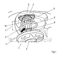
- Fig. 1 shows a strut 1, the component of a suspension not shown in detail Motor vehicle is.
- the strut 1 consists of a damper cylinder 2 and a piston rod 3.
- the piston rod is connected to a body 5.
- a suspension spring 6 of Suspension strut 1 extends around the piston rod 3.
- an additional spring 7 is arranged, which at maximum shortening of the shock absorber 1 between two end stops is effective, of which the first end stop 8 through the top of the Damper cylinder and the second end stop 9 is formed by the underside of the support bearing 4.
- the Additional spring 7 is designed in the present case as a foam element.
- a spacer element 10, designed here as a slotted plastic sleeve, at the Piston rod 3 are clipped.
- the spacer 10 fills the free length I between the free end the auxiliary spring 7 and the second end stop 9 substantially completely and provides for this Way for the additional spring 7 is effective for each spring deflection of the strut 1.
- the Einfederin of the shock absorber 1 and thus the compression possibility of the suspension are thus on the Limited by the additional spring 7 predetermined free path.
- the spacer element 10 consists of a Base body 11, which has a central and continuous receiving opening 12 for the piston rod 3.
- the receiving opening 12 has substantially the same diameter 19 as the piston rod 3, so that the spacer 10 is held there easily movable.
- a slot-shaped insertion opening 13 extends from the receiving opening 12 to the outside of the Distance element 10, wherein the width b of the insertion opening 13 is slightly smaller than the diameter of the Piston rod 3 is.
- the spacer 10 is made of glass fiber reinforced polyamide, a hard elastic plastic.
- the spacer element 10 In the dimensioning of the spacer element 10 are mainly acting in the longitudinal direction L forces to be considered between the auxiliary spring 3 and the end stop 9. Opposite the Insertion opening 13 are therefore a flattening 14 and a notch 15 attached, the total opposite the insertion opening 13 a significantly reduced cross section of the Deformationsiatas 10 effect.
- the deformation element in two legs 16, 17 split, which are connected by an elastic hinge 18 pivotally connected to each other.
- the spacer element 10 on the piston rod 3 can thus the legs 16, 17th swing apart and allow in this way the passage of the piston rod 3 through the Insertion opening 13.
- the pivot Leg 16, 17 through the elastic hinge 18 back to its original position, so that in total the spacer 10 is clipped onto the piston rod 3.
- the chamfer 19 shown in Fig. 3 allows tilting of the spacer element 10 when pushed on the piston rod 3.
- the chamfer 19 shown in Fig. 1 allows tilting of the spacer element 10 when pushed on the piston rod 3.
- FIG. 5 an alternative, hinged version of the spacer 10 is shown.
- the Distance element consists of two segments 20, 21, which are interconnected via a film hinge are.
- a detent 23 in the second segment 21 and a corresponding receiving opening in the first Segment 20 provide for the locking of Segente 20, 21 in the closed state.
- outside arranged recesses 26 form a point of attack for opening the closed Distance element 10, for example by means of a screwdriver, not shown.
Landscapes
- Engineering & Computer Science (AREA)
- Mechanical Engineering (AREA)
- General Engineering & Computer Science (AREA)
- Vehicle Body Suspensions (AREA)
- Fluid-Damping Devices (AREA)
- Hooks, Suction Cups, And Attachment By Adhesive Means (AREA)
- Centrifugal Separators (AREA)
- Discharge Heating (AREA)
Abstract
Description
- Fig. 1
- ein montiertes Distanzelement auf einem Federbein,
- Fig. 2
- eine Schrägansicht auf ein erfindungsgemäßes Distanzelement,
- Fig. 3
- eine Seitenansicht des Distanzelementes
- Fig. 4
- eine Draufsicht auf das Distanzelement, und
- Fig. 5
- eine alternative, klappbare Ausführung des Distanzelementes.
Claims (6)
- Vorrichtung zum Blockieren eines Radaufhängung mit einem Distanzelement, wobei die Radaufhängung zur Abstützung gegenüber einem Fahrzeugkörper eine Feder (6) und ein Dämpferelement (2)aufweist, das Dämpferelement eine Kolbenstange (3) und auf der Kolbenstange im Bereich eines ersten Endanschlages eine Zusatzfeder (7) aufweist, dadurch gekennzeichnet, dass das Distanzelement (10) aus mindestens einem Körper besteht, der auf der Kolbenstange (3) abnehmbar zwischen der Zusatzfeder (7) und einem zweiten Endanschlag (9) gehalten ist.
- Vorrichtung nach Anspruch 1, dadurch gekennzeichnet, dass das Distanzelement eine zentrale Aufnahme für die Kolbenstange sowie eine schlitzförmige Einführöffnung aufweist, wobei die Einführöffnung von der zentralen Aufnahme bis zur Außenseite des Distanzelementes erstreckt und die Breite der Einführöffnung geringfügig kleiner als der Durchmesser der Kolbenstange ist.
- Vorrichtung nach Anspruch 1, dadurch gekennzeichnet, dass das Distanzelement eine zentrale Aufnahme für die Kolbenstange aufweist und aus zwei zueinander klappbar und verriegelbar gehaltenen Segmenten besteht.
- Vorrichtung nach den Anspruch 2, dadurch gekennzeichnet, dass endseits am Distanzelement Schrägen vorgesehen sind.
- Vorrichtung nach einem der vorstehenden Ansprüche, dadurch gekennzeichnet, dass das Distanzelement aus hartelastischem Kunststoff besteht und gegenüberliegend der Einführöffnung eine Querschnittsverminderung aufweist.
- Vorrichtung nach einem der vorstehenden Ansprüche, dadurch gekennzeichnet, dass die Länge des Distanzelementes so gewählt ist, dass das Distanzelement die freie Länge der Kolbenstange zwischen der Zusatzfeder und dem zweiten Endanschlag bei vollständig ausgefedertem Dämpferelement vollständig ausfüllt.
Priority Applications (1)
| Application Number | Priority Date | Filing Date | Title |
|---|---|---|---|
| PL04011642T PL1498636T3 (pl) | 2003-07-18 | 2004-05-17 | Urządzenie do blokowania zawieszenia |
Applications Claiming Priority (2)
| Application Number | Priority Date | Filing Date | Title |
|---|---|---|---|
| DE10334034 | 2003-07-18 | ||
| DE10334034A DE10334034B3 (de) | 2003-07-18 | 2003-07-18 | Vorrichtung zum Blockieren einer Radaufhängung |
Publications (3)
| Publication Number | Publication Date |
|---|---|
| EP1498636A2 true EP1498636A2 (de) | 2005-01-19 |
| EP1498636A3 EP1498636A3 (de) | 2005-06-08 |
| EP1498636B1 EP1498636B1 (de) | 2006-11-22 |
Family
ID=32946482
Family Applications (1)
| Application Number | Title | Priority Date | Filing Date |
|---|---|---|---|
| EP04011642A Expired - Lifetime EP1498636B1 (de) | 2003-07-18 | 2004-05-17 | Vorrichtung zum Blockieren einer Radaufhängung |
Country Status (5)
| Country | Link |
|---|---|
| EP (1) | EP1498636B1 (de) |
| AT (1) | ATE346253T1 (de) |
| DE (2) | DE10334034B3 (de) |
| ES (1) | ES2273120T3 (de) |
| PL (1) | PL1498636T3 (de) |
Cited By (3)
| Publication number | Priority date | Publication date | Assignee | Title |
|---|---|---|---|---|
| EP1859971A1 (de) * | 2006-05-24 | 2007-11-28 | Dr.Ing. h.c.F. Porsche Aktiengesellschaft | Vorrichtung zum Blockieren eines Federbeins eines Kraftfahrzeugs |
| GB2478630A (en) * | 2010-03-09 | 2011-09-14 | Porsche Ag | Inastallation aid for installing a blocking element on a suspension strut |
| WO2021013947A1 (en) * | 2019-07-24 | 2021-01-28 | Fkt Koltuk Sistemleri Üretim Ve Dagitim Sanayi Ve Ticaret Anonim Sirketi | Backrest tilting angle adjusting clip |
Families Citing this family (6)
| Publication number | Priority date | Publication date | Assignee | Title |
|---|---|---|---|---|
| DE102006053298B4 (de) * | 2006-11-13 | 2009-10-15 | Bayerische Motoren Werke Aktiengesellschaft | Vorrichtung zum Blockieren einer Radaufhängung eines Fahrzeugs |
| US8498773B2 (en) | 2010-05-20 | 2013-07-30 | GM Global Technology Operations LLC | Stability enhancing system and method for enhancing the stability of a vehicle |
| ITMO20110102A1 (it) * | 2011-05-06 | 2012-11-07 | Go Vo Ni Srl | Dispositivo di montaggio per ammortizzatori, particolarmente per ammortizzatori a gas |
| DE102011101351A1 (de) | 2011-05-12 | 2012-11-15 | Audi Ag | Blockiervorrichtung für eine Radaufhängung eines Kraftfahrzeugs |
| DE102020113706B3 (de) * | 2020-05-20 | 2021-04-29 | Dr. Ing. H.C. F. Porsche Aktiengesellschaft | Montagehilfe und Verfahren zur Montage und Demontage von Blockierelementen an einem Federbein |
| DE102023207113A1 (de) * | 2023-07-26 | 2025-01-30 | Zf Friedrichshafen Ag | Modularer Abrollkolben, Wechselsatz für den Abrollkolben sowie Luftfeder mit dem Abrollkolben |
Citations (2)
| Publication number | Priority date | Publication date | Assignee | Title |
|---|---|---|---|---|
| DE2822105A1 (de) | 1978-05-20 | 1979-11-22 | Bayerische Motoren Werke Ag | Vorrichtung zum beeinflussen des federwegs und der federkennlinie einer federnden radaufhaengung von fahrzeugen |
| DE19751215C1 (de) | 1997-11-19 | 1998-12-10 | Porsche Ag | Vorrichtung zum Blockieren einer Feder in einem Federbein |
Family Cites Families (1)
| Publication number | Priority date | Publication date | Assignee | Title |
|---|---|---|---|---|
| IT1301787B1 (it) * | 1998-06-23 | 2000-07-07 | Cagiva Motor | Dispositivo antisollevamento di una forcella anteriore di unamotocicletta |
-
2003
- 2003-07-18 DE DE10334034A patent/DE10334034B3/de not_active Expired - Fee Related
-
2004
- 2004-05-17 AT AT04011642T patent/ATE346253T1/de active
- 2004-05-17 ES ES04011642T patent/ES2273120T3/es not_active Expired - Lifetime
- 2004-05-17 DE DE502004002055T patent/DE502004002055D1/de not_active Expired - Lifetime
- 2004-05-17 PL PL04011642T patent/PL1498636T3/pl unknown
- 2004-05-17 EP EP04011642A patent/EP1498636B1/de not_active Expired - Lifetime
Patent Citations (2)
| Publication number | Priority date | Publication date | Assignee | Title |
|---|---|---|---|---|
| DE2822105A1 (de) | 1978-05-20 | 1979-11-22 | Bayerische Motoren Werke Ag | Vorrichtung zum beeinflussen des federwegs und der federkennlinie einer federnden radaufhaengung von fahrzeugen |
| DE19751215C1 (de) | 1997-11-19 | 1998-12-10 | Porsche Ag | Vorrichtung zum Blockieren einer Feder in einem Federbein |
Cited By (6)
| Publication number | Priority date | Publication date | Assignee | Title |
|---|---|---|---|---|
| EP1859971A1 (de) * | 2006-05-24 | 2007-11-28 | Dr.Ing. h.c.F. Porsche Aktiengesellschaft | Vorrichtung zum Blockieren eines Federbeins eines Kraftfahrzeugs |
| US7419147B2 (en) | 2006-05-24 | 2008-09-02 | Dr. Ing. H.C. F. Porsche Ag | Device for blocking a suspension strut of a motor vehicle |
| GB2478630A (en) * | 2010-03-09 | 2011-09-14 | Porsche Ag | Inastallation aid for installing a blocking element on a suspension strut |
| GB2478630B (en) * | 2010-03-09 | 2012-07-04 | Porsche Ag | Installation aid |
| US8590127B2 (en) | 2010-03-09 | 2013-11-26 | Dr. Ing. H.C. F. Porsche Aktiengesellschaft | Installation aid |
| WO2021013947A1 (en) * | 2019-07-24 | 2021-01-28 | Fkt Koltuk Sistemleri Üretim Ve Dagitim Sanayi Ve Ticaret Anonim Sirketi | Backrest tilting angle adjusting clip |
Also Published As
| Publication number | Publication date |
|---|---|
| EP1498636B1 (de) | 2006-11-22 |
| ATE346253T1 (de) | 2006-12-15 |
| EP1498636A3 (de) | 2005-06-08 |
| ES2273120T3 (es) | 2007-05-01 |
| DE10334034B3 (de) | 2004-10-07 |
| DE502004002055D1 (de) | 2007-01-04 |
| PL1498636T3 (pl) | 2007-01-31 |
Similar Documents
| Publication | Publication Date | Title |
|---|---|---|
| DE2912533A1 (de) | Achsfederung | |
| DE4017275A1 (de) | Fahrzeug-radaufhaengung | |
| EP1498636B1 (de) | Vorrichtung zum Blockieren einer Radaufhängung | |
| DE102009015662B3 (de) | Federungsanordnung mit einer Blattfeder für ein Kraftfahrzeug | |
| DE19962026A1 (de) | Feder/Dämpferanordnung für ein Kraftfahrzeug | |
| DE3403882A1 (de) | Federaggregat, bestehend aus einer wendelfeder und einem oder mehreren federtellern | |
| DE10260060A1 (de) | Einzelradaufhängung mit Blattfeder für ein Kraftfahrzeug | |
| DE102015108484A1 (de) | Querblattfeder für ein Kraftfahrzeug sowie Achsanordnung mit einer Querblattfeder | |
| DE202008004420U1 (de) | Überrollschutzsystem für Kraftfahrzeuge | |
| DE8223449U1 (de) | Feder- und Dämpfungsvorrichtung für die Radaufhängung von Fahrzeugen | |
| DE2110072C3 (de) | Achsführung an einem Drehgestell für Schienenfahrzeuge, insbesondere für Güterwagen | |
| DE102006057891B4 (de) | Wankstabilisierungs- und Wankdämpfungs-Anordnung für ein zweispuriges Fahrzeug | |
| DE10344102B3 (de) | Federträger mit einer Zusatzfeder | |
| DE2822105A1 (de) | Vorrichtung zum beeinflussen des federwegs und der federkennlinie einer federnden radaufhaengung von fahrzeugen | |
| DE19956090A1 (de) | Federbein für eine Hinterachse eines Kraftfahrzeuges | |
| DE102016105958B4 (de) | Federbein für ein Kraftfahrzeug | |
| DE102015010314B4 (de) | Arretierungsanordnung | |
| DE3517239C2 (de) | ||
| DE20112112U1 (de) | Federungseinrichtung insbesondere für ein Kinderfahrzeug | |
| DE102017101038A1 (de) | Axiallager zur Lagerung eines Achsschenkels sowie Achsschenkellageranordnung mit dem Axiallager | |
| DE3124837C2 (de) | Transportfahrzeug, insbesondere Anhängerfahrzeug | |
| DE19911340A1 (de) | Radaufhängung für ein Kraftfahrzeug | |
| EP4080079A2 (de) | Bremsvorrichtung | |
| DE19804699A1 (de) | Einzelradaufhängung für nichtgelenkte Räder von Kraftfahrzeugen | |
| DE2356586A1 (de) | Axial belastbares lager fuer gelenke |
Legal Events
| Date | Code | Title | Description |
|---|---|---|---|
| PUAI | Public reference made under article 153(3) epc to a published international application that has entered the european phase |
Free format text: ORIGINAL CODE: 0009012 |
|
| AK | Designated contracting states |
Kind code of ref document: A2 Designated state(s): AT BE BG CH CY CZ DE DK EE ES FI FR GB GR HU IE IT LI LU MC NL PL PT RO SE SI SK TR |
|
| AX | Request for extension of the european patent |
Extension state: AL HR LT LV MK |
|
| PUAL | Search report despatched |
Free format text: ORIGINAL CODE: 0009013 |
|
| AK | Designated contracting states |
Kind code of ref document: A3 Designated state(s): AT BE BG CH CY CZ DE DK EE ES FI FR GB GR HU IE IT LI LU MC NL PL PT RO SE SI SK TR |
|
| AX | Request for extension of the european patent |
Extension state: AL HR LT LV MK |
|
| 17P | Request for examination filed |
Effective date: 20051208 |
|
| AKX | Designation fees paid |
Designated state(s): AT BE BG CH CY CZ DE DK EE ES FI FR GB GR HU IE IT LI LU MC NL PL PT RO SE SI SK TR |
|
| GRAP | Despatch of communication of intention to grant a patent |
Free format text: ORIGINAL CODE: EPIDOSNIGR1 |
|
| GRAC | Information related to communication of intention to grant a patent modified |
Free format text: ORIGINAL CODE: EPIDOSCIGR1 |
|
| GRAS | Grant fee paid |
Free format text: ORIGINAL CODE: EPIDOSNIGR3 |
|
| GRAA | (expected) grant |
Free format text: ORIGINAL CODE: 0009210 |
|
| AK | Designated contracting states |
Kind code of ref document: B1 Designated state(s): AT BE BG CH CY CZ DE DK EE ES FI FR GB GR HU IE IT LI LU MC NL PL PT RO SE SI SK TR |
|
| PG25 | Lapsed in a contracting state [announced via postgrant information from national office to epo] |
Ref country code: IT Free format text: LAPSE BECAUSE OF FAILURE TO SUBMIT A TRANSLATION OF THE DESCRIPTION OR TO PAY THE FEE WITHIN THE PRESCRIBED TIME-LIMIT;WARNING: LAPSES OF ITALIAN PATENTS WITH EFFECTIVE DATE BEFORE 2007 MAY HAVE OCCURRED AT ANY TIME BEFORE 2007. THE CORRECT EFFECTIVE DATE MAY BE DIFFERENT FROM THE ONE RECORDED. Effective date: 20061122 Ref country code: IE Free format text: LAPSE BECAUSE OF FAILURE TO SUBMIT A TRANSLATION OF THE DESCRIPTION OR TO PAY THE FEE WITHIN THE PRESCRIBED TIME-LIMIT Effective date: 20061122 Ref country code: SI Free format text: LAPSE BECAUSE OF FAILURE TO SUBMIT A TRANSLATION OF THE DESCRIPTION OR TO PAY THE FEE WITHIN THE PRESCRIBED TIME-LIMIT Effective date: 20061122 Ref country code: FI Free format text: LAPSE BECAUSE OF FAILURE TO SUBMIT A TRANSLATION OF THE DESCRIPTION OR TO PAY THE FEE WITHIN THE PRESCRIBED TIME-LIMIT Effective date: 20061122 Ref country code: RO Free format text: LAPSE BECAUSE OF FAILURE TO SUBMIT A TRANSLATION OF THE DESCRIPTION OR TO PAY THE FEE WITHIN THE PRESCRIBED TIME-LIMIT Effective date: 20061122 Ref country code: SK Free format text: LAPSE BECAUSE OF FAILURE TO SUBMIT A TRANSLATION OF THE DESCRIPTION OR TO PAY THE FEE WITHIN THE PRESCRIBED TIME-LIMIT Effective date: 20061122 |
|
| REG | Reference to a national code |
Ref country code: GB Ref legal event code: FG4D Free format text: NOT ENGLISH |
|
| REG | Reference to a national code |
Ref country code: CH Ref legal event code: EP |
|
| REG | Reference to a national code |
Ref country code: IE Ref legal event code: FG4D Free format text: LANGUAGE OF EP DOCUMENT: GERMAN |
|
| REF | Corresponds to: |
Ref document number: 502004002055 Country of ref document: DE Date of ref document: 20070104 Kind code of ref document: P |
|
| REG | Reference to a national code |
Ref country code: PL Ref legal event code: T3 |
|
| PG25 | Lapsed in a contracting state [announced via postgrant information from national office to epo] |
Ref country code: BG Free format text: LAPSE BECAUSE OF FAILURE TO SUBMIT A TRANSLATION OF THE DESCRIPTION OR TO PAY THE FEE WITHIN THE PRESCRIBED TIME-LIMIT Effective date: 20070222 Ref country code: DK Free format text: LAPSE BECAUSE OF FAILURE TO SUBMIT A TRANSLATION OF THE DESCRIPTION OR TO PAY THE FEE WITHIN THE PRESCRIBED TIME-LIMIT Effective date: 20070222 |
|
| REG | Reference to a national code |
Ref country code: SE Ref legal event code: TRGR |
|
| GBT | Gb: translation of ep patent filed (gb section 77(6)(a)/1977) |
Effective date: 20070212 |
|
| ET | Fr: translation filed | ||
| PG25 | Lapsed in a contracting state [announced via postgrant information from national office to epo] |
Ref country code: PT Free format text: LAPSE BECAUSE OF FAILURE TO SUBMIT A TRANSLATION OF THE DESCRIPTION OR TO PAY THE FEE WITHIN THE PRESCRIBED TIME-LIMIT Effective date: 20070423 |
|
| REG | Reference to a national code |
Ref country code: ES Ref legal event code: FG2A Ref document number: 2273120 Country of ref document: ES Kind code of ref document: T3 |
|
| REG | Reference to a national code |
Ref country code: IE Ref legal event code: FD4D |
|
| PLBE | No opposition filed within time limit |
Free format text: ORIGINAL CODE: 0009261 |
|
| STAA | Information on the status of an ep patent application or granted ep patent |
Free format text: STATUS: NO OPPOSITION FILED WITHIN TIME LIMIT |
|
| 26N | No opposition filed |
Effective date: 20070823 |
|
| PG25 | Lapsed in a contracting state [announced via postgrant information from national office to epo] |
Ref country code: MC Free format text: LAPSE BECAUSE OF NON-PAYMENT OF DUE FEES Effective date: 20070531 |
|
| PG25 | Lapsed in a contracting state [announced via postgrant information from national office to epo] |
Ref country code: GR Free format text: LAPSE BECAUSE OF FAILURE TO SUBMIT A TRANSLATION OF THE DESCRIPTION OR TO PAY THE FEE WITHIN THE PRESCRIBED TIME-LIMIT Effective date: 20070223 |
|
| PGFP | Annual fee paid to national office [announced via postgrant information from national office to epo] |
Ref country code: ES Payment date: 20080529 Year of fee payment: 5 |
|
| REG | Reference to a national code |
Ref country code: CH Ref legal event code: PL |
|
| PG25 | Lapsed in a contracting state [announced via postgrant information from national office to epo] |
Ref country code: EE Free format text: LAPSE BECAUSE OF FAILURE TO SUBMIT A TRANSLATION OF THE DESCRIPTION OR TO PAY THE FEE WITHIN THE PRESCRIBED TIME-LIMIT Effective date: 20061122 Ref country code: LI Free format text: LAPSE BECAUSE OF NON-PAYMENT OF DUE FEES Effective date: 20080531 Ref country code: CH Free format text: LAPSE BECAUSE OF NON-PAYMENT OF DUE FEES Effective date: 20080531 |
|
| REG | Reference to a national code |
Ref country code: FR Ref legal event code: TP |
|
| PGFP | Annual fee paid to national office [announced via postgrant information from national office to epo] |
Ref country code: NL Payment date: 20090527 Year of fee payment: 6 |
|
| PG25 | Lapsed in a contracting state [announced via postgrant information from national office to epo] |
Ref country code: LU Free format text: LAPSE BECAUSE OF NON-PAYMENT OF DUE FEES Effective date: 20070517 Ref country code: CY Free format text: LAPSE BECAUSE OF FAILURE TO SUBMIT A TRANSLATION OF THE DESCRIPTION OR TO PAY THE FEE WITHIN THE PRESCRIBED TIME-LIMIT Effective date: 20061122 |
|
| PGFP | Annual fee paid to national office [announced via postgrant information from national office to epo] |
Ref country code: SE Payment date: 20090514 Year of fee payment: 6 |
|
| PG25 | Lapsed in a contracting state [announced via postgrant information from national office to epo] |
Ref country code: TR Free format text: LAPSE BECAUSE OF FAILURE TO SUBMIT A TRANSLATION OF THE DESCRIPTION OR TO PAY THE FEE WITHIN THE PRESCRIBED TIME-LIMIT Effective date: 20061122 Ref country code: HU Free format text: LAPSE BECAUSE OF FAILURE TO SUBMIT A TRANSLATION OF THE DESCRIPTION OR TO PAY THE FEE WITHIN THE PRESCRIBED TIME-LIMIT Effective date: 20070523 |
|
| PGFP | Annual fee paid to national office [announced via postgrant information from national office to epo] |
Ref country code: BE Payment date: 20090622 Year of fee payment: 6 |
|
| REG | Reference to a national code |
Ref country code: FR Ref legal event code: CD |
|
| REG | Reference to a national code |
Ref country code: ES Ref legal event code: FD2A Effective date: 20090518 |
|
| PG25 | Lapsed in a contracting state [announced via postgrant information from national office to epo] |
Ref country code: ES Free format text: LAPSE BECAUSE OF NON-PAYMENT OF DUE FEES Effective date: 20090518 |
|
| BERE | Be: lapsed |
Owner name: DR.ING. H.C.F. PORSCHE A.G. Effective date: 20100531 |
|
| REG | Reference to a national code |
Ref country code: NL Ref legal event code: V1 Effective date: 20101201 |
|
| REG | Reference to a national code |
Ref country code: FR Ref legal event code: TP |
|
| EUG | Se: european patent has lapsed | ||
| PG25 | Lapsed in a contracting state [announced via postgrant information from national office to epo] |
Ref country code: SE Free format text: LAPSE BECAUSE OF NON-PAYMENT OF DUE FEES Effective date: 20100518 Ref country code: NL Free format text: LAPSE BECAUSE OF NON-PAYMENT OF DUE FEES Effective date: 20101201 Ref country code: BE Free format text: LAPSE BECAUSE OF NON-PAYMENT OF DUE FEES Effective date: 20100531 |
|
| REG | Reference to a national code |
Ref country code: GB Ref legal event code: 732E Free format text: REGISTERED BETWEEN 20110310 AND 20110316 |
|
| REG | Reference to a national code |
Ref country code: GB Ref legal event code: 732E Free format text: REGISTERED BETWEEN 20110331 AND 20110406 |
|
| PGFP | Annual fee paid to national office [announced via postgrant information from national office to epo] |
Ref country code: CZ Payment date: 20120515 Year of fee payment: 9 |
|
| PGFP | Annual fee paid to national office [announced via postgrant information from national office to epo] |
Ref country code: PL Payment date: 20120511 Year of fee payment: 9 |
|
| PG25 | Lapsed in a contracting state [announced via postgrant information from national office to epo] |
Ref country code: CZ Free format text: LAPSE BECAUSE OF NON-PAYMENT OF DUE FEES Effective date: 20130517 |
|
| PG25 | Lapsed in a contracting state [announced via postgrant information from national office to epo] |
Ref country code: PL Free format text: LAPSE BECAUSE OF NON-PAYMENT OF DUE FEES Effective date: 20130517 |
|
| REG | Reference to a national code |
Ref country code: PL Ref legal event code: LAPE |
|
| REG | Reference to a national code |
Ref country code: FR Ref legal event code: PLFP Year of fee payment: 13 |
|
| REG | Reference to a national code |
Ref country code: FR Ref legal event code: PLFP Year of fee payment: 14 |
|
| REG | Reference to a national code |
Ref country code: FR Ref legal event code: PLFP Year of fee payment: 15 |
|
| PGFP | Annual fee paid to national office [announced via postgrant information from national office to epo] |
Ref country code: DE Payment date: 20210528 Year of fee payment: 18 Ref country code: FR Payment date: 20210520 Year of fee payment: 18 |
|
| PGFP | Annual fee paid to national office [announced via postgrant information from national office to epo] |
Ref country code: GB Payment date: 20210520 Year of fee payment: 18 Ref country code: AT Payment date: 20210520 Year of fee payment: 18 |
|
| REG | Reference to a national code |
Ref country code: DE Ref legal event code: R119 Ref document number: 502004002055 Country of ref document: DE |
|
| REG | Reference to a national code |
Ref country code: AT Ref legal event code: MM01 Ref document number: 346253 Country of ref document: AT Kind code of ref document: T Effective date: 20220517 |
|
| GBPC | Gb: european patent ceased through non-payment of renewal fee |
Effective date: 20220517 |
|
| PG25 | Lapsed in a contracting state [announced via postgrant information from national office to epo] |
Ref country code: AT Free format text: LAPSE BECAUSE OF NON-PAYMENT OF DUE FEES Effective date: 20220517 |
|
| PG25 | Lapsed in a contracting state [announced via postgrant information from national office to epo] |
Ref country code: FR Free format text: LAPSE BECAUSE OF NON-PAYMENT OF DUE FEES Effective date: 20220531 |
|
| PG25 | Lapsed in a contracting state [announced via postgrant information from national office to epo] |
Ref country code: GB Free format text: LAPSE BECAUSE OF NON-PAYMENT OF DUE FEES Effective date: 20220517 Ref country code: DE Free format text: LAPSE BECAUSE OF NON-PAYMENT OF DUE FEES Effective date: 20221201 |