EP1498652A1 - Procédé de connexion d'un embout d'emmanchement avec un tuyau et dispositif pour la mise en oeuvre de ce procédé - Google Patents
Procédé de connexion d'un embout d'emmanchement avec un tuyau et dispositif pour la mise en oeuvre de ce procédé Download PDFInfo
- Publication number
- EP1498652A1 EP1498652A1 EP04025027A EP04025027A EP1498652A1 EP 1498652 A1 EP1498652 A1 EP 1498652A1 EP 04025027 A EP04025027 A EP 04025027A EP 04025027 A EP04025027 A EP 04025027A EP 1498652 A1 EP1498652 A1 EP 1498652A1
- Authority
- EP
- European Patent Office
- Prior art keywords
- pressing
- marking
- pressing device
- press fitting
- coating
- Prior art date
- Legal status (The legal status is an assumption and is not a legal conclusion. Google has not performed a legal analysis and makes no representation as to the accuracy of the status listed.)
- Granted
Links
Images
Classifications
-
- F—MECHANICAL ENGINEERING; LIGHTING; HEATING; WEAPONS; BLASTING
- F16—ENGINEERING ELEMENTS AND UNITS; GENERAL MEASURES FOR PRODUCING AND MAINTAINING EFFECTIVE FUNCTIONING OF MACHINES OR INSTALLATIONS; THERMAL INSULATION IN GENERAL
- F16L—PIPES; JOINTS OR FITTINGS FOR PIPES; SUPPORTS FOR PIPES, CABLES OR PROTECTIVE TUBING; MEANS FOR THERMAL INSULATION IN GENERAL
- F16L13/00—Non-disconnectable pipe joints, e.g. soldered, adhesive, or caulked joints
- F16L13/14—Non-disconnectable pipe joints, e.g. soldered, adhesive, or caulked joints made by plastically deforming the material of the pipe, e.g. by flanging, rolling
- F16L13/141—Non-disconnectable pipe joints, e.g. soldered, adhesive, or caulked joints made by plastically deforming the material of the pipe, e.g. by flanging, rolling by crimping or rolling from the outside
- F16L13/142—Non-disconnectable pipe joints, e.g. soldered, adhesive, or caulked joints made by plastically deforming the material of the pipe, e.g. by flanging, rolling by crimping or rolling from the outside with a sealing element inserted into the female part before crimping or rolling
-
- F—MECHANICAL ENGINEERING; LIGHTING; HEATING; WEAPONS; BLASTING
- F16—ENGINEERING ELEMENTS AND UNITS; GENERAL MEASURES FOR PRODUCING AND MAINTAINING EFFECTIVE FUNCTIONING OF MACHINES OR INSTALLATIONS; THERMAL INSULATION IN GENERAL
- F16L—PIPES; JOINTS OR FITTINGS FOR PIPES; SUPPORTS FOR PIPES, CABLES OR PROTECTIVE TUBING; MEANS FOR THERMAL INSULATION IN GENERAL
- F16L2201/00—Special arrangements for pipe couplings
- F16L2201/10—Indicators for correct coupling
Definitions
- the invention relates to a method for connecting a Press fitting with a tube by means of a pressing device, at the press fitting and pipe to a certain insertion depth nested and then the press fitting and / or the Pipe with the aid of the pressing device radially inward plastically is deformed or become, wherein the pressing device with a Marking device is provided by means of the frame a marking is applied to a pressing operation.
- the invention further relates to a pressing device for Implementation of this procedure.
- the compression of the press fitting and the tube happens with the help of pressing devices, as in various embodiments for example from DE-C-21 36 782, DE-A-34 23 283, EP-A-0 451 806, EP-B-0 361 630, DE-C-42 40,427 and DE-A-196 31 019 are known.
- the pressing devices have two or more cheek plates during the pressing process radially inwards to form a closed baling chamber can be moved.
- a drive to move the Preßbacken is often provided a hydraulic piston, the over a hand-driven or electric motor driven Pump be pressurized with hydraulic pressure can.
- a cheek plate with a marking device in the form of a Provide recess lying in the pressing direction so that during the pressing process in the surface of the press fitting characteristic embossed character is formed, whose Appearance depends on the quality of the compression (see DE-C-196 20 165).
- This is the responsibility of the client commissioned control give the opportunity after pressing visually inspect all the compression points and the severity to examine the embossing mark.
- the invention is based on the object, a method for connecting press fittings to a pipe, after its application is clearly recognizable, whether a complete compression has been performed.
- a further object is to design a pressing device in such a way that so that the procedure be carried out can.
- the first object is achieved according to the invention that only a mark is applied when the pressing tool has reached its Endpreß too.
- a mark only then on apply the joint area if ensured is that the pressing tool reaches its Endpreßwolf has, so a complete compression of the connection from Preßfitting and pipe has taken place.
- the mark then not only - as in the prior art - the Information that any compression took place has, but in addition the high certainty that the compression has been properly carried out and thus the connection is tight.
- the mark is formed by a pressure member, with the applied a pressure mark on the connection area can be, for example in the form of an embossing or a print.
- the mark also by means of an energy steel, for example one Laser or spark erosion beam to be applied.
- an energy steel for example one Laser or spark erosion beam to be applied.
- a burn-in mark to produce or apply a color mark.
- the tube with a to the range of insertion adjacent coating is provided.
- a controller can then determine if the connection also so far properly made, so the pipe for implementation the compression pushed sufficiently far into the press fitting has been. This is a comprehensive control the pipe connection possible.
- the second part of the task according to the invention solved that the pressing device with a pickup for detecting the Endpreßwolf is provided with the marking cooperates in such a way that the marking device is activated only if and only if the pressing tool has reached its final pressing position. On This way, it is ensured that the mark only is attached after proper compression.
- pickup for detecting the Endpreß too are, for example DE-A-196 31 019 can be seen.
- the marker can as separate pressure element for generating a pressure mark be educated.
- the marking device may alternatively comprise a device for generating an energy beam, for example a laser beam or a spark erosion beam, with the one on the coating, for example generated in the form of a burn-in marking becomes.
- an energy beam for example a laser beam or a spark erosion beam
- the one on the coating for example generated in the form of a burn-in marking becomes.
- the same can be done with a trained as Schust Zi Marking be achieved. Also in this Case are clear in combination with the coating recognizable contrasts can be produced.
- Possibility of the marking device as a color marking device train.
- connection region has a coating or Not.
- the mark is on or in the coating made while in the latter case the marking applied directly to the connection area becomes.
- the pressing devices can also be a sensor for Detecting a coating on the pipe.
- One such sensor should then be arranged and with a Device for giving an attention sign be connected in such a way that generates an attention sign when the sensor is pressing the coating not detected. In this way receives the compression person performing a note automatically Make sure that the pipe does not go far enough into the press fitting has been inserted.
- the sensor is arranged and with a Locking device for the drive of the pressing device such is connected, that the drive is locked when the Sensor at the beginning of the pressing process not the coating detected.
- a compression is with the help of such Pressing device only possible if the pipe with the provided Inserted depth inserted into the press fitting since then only the coating from the sensor detected at the beginning of the pressing and thus the drive is released.
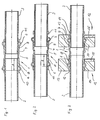
- the pipe connection shown in Figure 1 consists of a press fitting 1 and two end faces, only partially illustrated tubes 2, 3, in the Preßfitting 1 inserted from one side or the other are.
- the press fitting 1 has a cylinder portion 4 with a serving as a stop for the tubes 2, 3, central constriction 5.
- the press fitting 1 outwardly curved annular beads 6, 7, in the inside one elastomeric each Seal is inserted, its representation here but has been dispensed with. Both tubes 2, 3 are around the intended insertion depth 1 is inserted and lie therefore at the constriction 5.
- the press fitting 1 has immediately adjacent to the annular beads 6, 7 ring-shaped coatings 8, 9 on.
- These coatings 8, 9 are of the pressing device during compression of the Pressed fitting 1 applied radially inwards.
- the coatings 8, 9 are designed to look their best due to the strong pressure of the pressing device change during the compression, for example impressed be destroyed or that the material of the Press fitting 1 comes to light. Also the others, above-described embodiments and mechanisms of action coatings are possible. In all cases signals the change in the coatings 8, 9, that a compression has been made.
- the tubes 2, 3 have plastic rings 10, 11, which the Tubes 2, 3 tightly surrounding and beyond the areas the insertion depth 1, but arranged adjacent to this are. Due to the fact that the plastic rings 10, 11 to the End faces of the annular beads 6, 7 rest, is from the outside recognizable that the tubes 2, 3 sufficiently far in the Preßfitting 1 are inserted.
- the plastic rings 10, 11 are formed so thick that they too when pressing be detected by the pressing device, so that they look during compression change, such as pressure marks received or the like. In this way In addition, the inspector is assured that the Tubes 2, 3 sufficiently far before the pressing process were inserted.
- FIG. 3 shows the pipe connection shown in FIG with attached pressing tool 12. It is understood that the pressing tool 12 is not simultaneously at both ends of the press fitting 1 can be attached. Rather, be the crimping performed in succession.
- the pressing tool 12 has in a known manner (see. For example, DE-A-196 31 019 and the cited therein Prior art) an upper and a lower cheek piece 13, 14, the part of a not shown here Preßeries are and with the help of a to this pressing device belonging drive for the purpose of radial compression of the press fitting 1 and the tubes 2, 3 against each other can be moved. It can be seen that the cheek plates 13, 14 in the compression of the left-hand part the press fitting 1 with the annular bead 6 both the coating 8 as well as the plastic ring 10 act. When merging the cheek plates 13, 14 are Therefore, this pressurized and suffer from this a subsequently visually recognizable change of her appearance. The change depends on the type the coating 8 or the plastic ring 10. In that regard Reference is made to the above general description.
- the lower cheek piece 14 is provided with a touch sensor 15, the example by means of spring bias radially pressed inwards. At the left side pressing it is applied to the coating 8 and takes it a position in which he has no attention generated and / or not blocked the drive. It It is understood that his position depends on a corresponding Switching device detected and to a control device which is the generation of an attention sign and / or the release or blocking of the Drive controls.
Landscapes
- Engineering & Computer Science (AREA)
- General Engineering & Computer Science (AREA)
- Mechanical Engineering (AREA)
- Lining Or Joining Of Plastics Or The Like (AREA)
- Automatic Assembly (AREA)
- Application Of Or Painting With Fluid Materials (AREA)
Priority Applications (1)
| Application Number | Priority Date | Filing Date | Title |
|---|---|---|---|
| DE20023812U DE20023812U1 (de) | 1999-09-21 | 2000-07-21 | Preßgerät zur Verbindung eines Preßfittings mit einem Rohr |
Applications Claiming Priority (3)
| Application Number | Priority Date | Filing Date | Title |
|---|---|---|---|
| DE19945113 | 1999-09-21 | ||
| DE1999145113 DE19945113A1 (de) | 1999-09-21 | 1999-09-21 | Verfahren zur Verbindung eines Preßfittings it einem Rohr sowie Preßfitting, Rohr und Preßgerät zur Durchführung dieses Verfahrens |
| EP00956246A EP1214543B1 (fr) | 1999-09-21 | 2000-07-21 | Procede pour relier un raccord a emmancher a la presse et un tuyau, raccord a emmancher a la presse, et presse servant a mettre en oeuvre ledit procede |
Related Parent Applications (2)
| Application Number | Title | Priority Date | Filing Date |
|---|---|---|---|
| EP00956246A Division EP1214543B1 (fr) | 1999-09-21 | 2000-07-21 | Procede pour relier un raccord a emmancher a la presse et un tuyau, raccord a emmancher a la presse, et presse servant a mettre en oeuvre ledit procede |
| EP00956246A Division-Into EP1214543B1 (fr) | 1999-09-21 | 2000-07-21 | Procede pour relier un raccord a emmancher a la presse et un tuyau, raccord a emmancher a la presse, et presse servant a mettre en oeuvre ledit procede |
Publications (2)
| Publication Number | Publication Date |
|---|---|
| EP1498652A1 true EP1498652A1 (fr) | 2005-01-19 |
| EP1498652B1 EP1498652B1 (fr) | 2006-03-29 |
Family
ID=7922704
Family Applications (2)
| Application Number | Title | Priority Date | Filing Date |
|---|---|---|---|
| EP04025027A Expired - Lifetime EP1498652B1 (fr) | 1999-09-21 | 2000-07-21 | Procédé de connexion d'un embout d'emmanchement avec un tuyau et dispositif pour la mise en oeuvre de ce procédé |
| EP00956246A Expired - Lifetime EP1214543B1 (fr) | 1999-09-21 | 2000-07-21 | Procede pour relier un raccord a emmancher a la presse et un tuyau, raccord a emmancher a la presse, et presse servant a mettre en oeuvre ledit procede |
Family Applications After (1)
| Application Number | Title | Priority Date | Filing Date |
|---|---|---|---|
| EP00956246A Expired - Lifetime EP1214543B1 (fr) | 1999-09-21 | 2000-07-21 | Procede pour relier un raccord a emmancher a la presse et un tuyau, raccord a emmancher a la presse, et presse servant a mettre en oeuvre ledit procede |
Country Status (4)
| Country | Link |
|---|---|
| EP (2) | EP1498652B1 (fr) |
| DE (3) | DE19945113A1 (fr) |
| ES (1) | ES2338632T3 (fr) |
| WO (1) | WO2001021997A1 (fr) |
Cited By (1)
| Publication number | Priority date | Publication date | Assignee | Title |
|---|---|---|---|---|
| EP3055599A4 (fr) * | 2013-10-11 | 2017-08-09 | Quick Fitting, Inc. | Dispositif de raccordement par pressage, composants et procédé |
Families Citing this family (14)
| Publication number | Priority date | Publication date | Assignee | Title |
|---|---|---|---|---|
| FR2846396B1 (fr) * | 2002-10-24 | 2005-05-13 | Comap | Raccord a sertir a securite renforcee |
| DE10319376B4 (de) * | 2003-04-30 | 2007-01-04 | Uponor Innovation Ab | Pressbacke für ein Presswerkzeug zum Verpressen von Fittingen, Presswerkzeug und Werkzeug zum axialen Aufschieben einer Hülse |
| DE20315938U1 (de) * | 2003-10-16 | 2005-02-24 | Ipa Produktions- & Vertriebsges. M.B.H. | Werkzeug zur Durchführung eines Verbindungsvorganges sowie Haltehülse |
| FR2866689B1 (fr) * | 2004-02-19 | 2006-03-24 | Comap | Raccord a sertir comprenant une bague secable |
| DE102004016110B4 (de) | 2004-04-01 | 2017-03-30 | Gustav Klauke Gmbh | Presshebel für ein Verpressgerät sowie Verfahren zur Überprüfung der Vollständigkeit einer Verpressung |
| FR2870314B1 (fr) * | 2004-05-14 | 2006-06-23 | Comap Sa | Bague de visualisation du sertissage d'un raccord pour tubes |
| FR2873780B1 (fr) * | 2004-07-29 | 2006-09-08 | Comap Sa | Bague de visualisation du sertissage d'un raccord pour tubes |
| DE102005028558B3 (de) * | 2005-06-21 | 2007-01-04 | Uponor Innovation Ab | Pressfitting für ein Rohr |
| DE102008027812A1 (de) | 2008-06-11 | 2010-01-14 | Novopress Gmbh Pressen Und Presswerkzeuge & Co. Kg | Verfahren zur Verbindung von zwei Werkstücken sowie Pressfitting hierfür |
| NL2006754C2 (en) * | 2011-05-10 | 2012-11-13 | Vsh Fittings B V | Pipeline components having prefab insertion depth markings. |
| DE102018109555B3 (de) | 2018-04-20 | 2019-10-24 | Uponor Innovation Ab | Pressfitting für eine Rohrverbindung und Verfahren zu seiner Herstellung |
| EP3587889B1 (fr) | 2018-06-22 | 2023-08-30 | Crompton Technology Group Limited | Ensemble de tuyau composite |
| USD888899S1 (en) | 2018-12-21 | 2020-06-30 | Uponor Innovation Ab | Fitting for pipe installations |
| DE102020200391B4 (de) * | 2020-01-14 | 2024-11-21 | Vega Grieshaber Kg | Nicht lösbare Sensoranordnung |
Citations (11)
| Publication number | Priority date | Publication date | Assignee | Title |
|---|---|---|---|---|
| DE1187870B (de) | 1958-10-01 | 1965-02-25 | Aga Plaatfoeraedling Aktiebola | Plastisch verformbare metallische Kupplungshuelse zum Verbinden von Metallrohren mit glatten Enden |
| DE2136782C2 (de) | 1971-07-23 | 1982-12-02 | Novopress GmbH Pressen und Presswerkzeuge & Co KG, 4000 Düsseldorf | Tragbares druckmittelbetriebenes Klemmwerkzeug |
| DE3423283A1 (de) | 1984-06-23 | 1986-01-02 | Helmut Dipl.-Ing. 4040 Neuss Dischler | Klemmwerkzeug, insbesondere zum verbinden von rohren und anderen profilen |
| EP0451806A1 (fr) | 1990-04-12 | 1991-10-16 | Helmut Dipl.-Ing. Dischler | Outil de pressage |
| EP0361630B1 (fr) | 1988-09-30 | 1992-06-10 | MANNESMANN Aktiengesellschaft | Méthode et dispositif et raccord à comprenion pour fabriquer une jonction inséparable, hermétique pour tuyaux |
| CH682942A5 (de) * | 1991-04-22 | 1993-12-15 | Geberit Ag | Verbindungsteil für eine Pressverbindung. |
| DE4240427C1 (de) | 1992-12-02 | 1994-01-20 | Novopress Gmbh | Preßwerkzeug |
| DE19631019A1 (de) | 1996-02-09 | 1997-08-14 | Novopress Gmbh | Preßgerät |
| DE19620165C1 (de) | 1996-05-08 | 1997-10-16 | Mannesmann Ag | Verfahren und Vorrichtung zum Herstellen einer Rohrpreßverbindung |
| US5824906A (en) * | 1993-08-26 | 1998-10-20 | Novopress Gmbh Pressen Und Presswerkzeuge & Co. Kg | Pressing tool |
| EP0879985A1 (fr) * | 1997-05-20 | 1998-11-25 | Georg Jäggi | Raccords à compression pour tuyaux |
Family Cites Families (4)
| Publication number | Priority date | Publication date | Assignee | Title |
|---|---|---|---|---|
| US5690146A (en) * | 1996-08-20 | 1997-11-25 | Aeroquip Corporation | Hose and method for wear detection |
| DE19748945C1 (de) * | 1997-10-24 | 1999-02-11 | Mannesmann Ag | Rohrverbindung |
| DE29908561U1 (de) * | 1998-07-08 | 1999-08-12 | Mannesmann AG, 40213 Düsseldorf | Kombination aus Fitting, Rohr und Preßgerät zum unlösbaren Verbinden eines Rohres mit einem Fitting |
| DE29915400U1 (de) * | 1999-09-02 | 1999-12-09 | Franz Viegener II GmbH & Co. KG, 57439 Attendorn | Fitting oder Armatur zur Erstellung einer Preßverbindung mit einem eingesteckten Rohrende |
-
1999
- 1999-09-21 DE DE1999145113 patent/DE19945113A1/de not_active Ceased
-
2000
- 2000-07-21 WO PCT/EP2000/007013 patent/WO2001021997A1/fr not_active Ceased
- 2000-07-21 ES ES00956246T patent/ES2338632T3/es not_active Expired - Lifetime
- 2000-07-21 EP EP04025027A patent/EP1498652B1/fr not_active Expired - Lifetime
- 2000-07-21 DE DE50012501T patent/DE50012501D1/de not_active Expired - Lifetime
- 2000-07-21 EP EP00956246A patent/EP1214543B1/fr not_active Expired - Lifetime
- 2000-07-21 DE DE50015860T patent/DE50015860D1/de not_active Expired - Lifetime
Patent Citations (11)
| Publication number | Priority date | Publication date | Assignee | Title |
|---|---|---|---|---|
| DE1187870B (de) | 1958-10-01 | 1965-02-25 | Aga Plaatfoeraedling Aktiebola | Plastisch verformbare metallische Kupplungshuelse zum Verbinden von Metallrohren mit glatten Enden |
| DE2136782C2 (de) | 1971-07-23 | 1982-12-02 | Novopress GmbH Pressen und Presswerkzeuge & Co KG, 4000 Düsseldorf | Tragbares druckmittelbetriebenes Klemmwerkzeug |
| DE3423283A1 (de) | 1984-06-23 | 1986-01-02 | Helmut Dipl.-Ing. 4040 Neuss Dischler | Klemmwerkzeug, insbesondere zum verbinden von rohren und anderen profilen |
| EP0361630B1 (fr) | 1988-09-30 | 1992-06-10 | MANNESMANN Aktiengesellschaft | Méthode et dispositif et raccord à comprenion pour fabriquer une jonction inséparable, hermétique pour tuyaux |
| EP0451806A1 (fr) | 1990-04-12 | 1991-10-16 | Helmut Dipl.-Ing. Dischler | Outil de pressage |
| CH682942A5 (de) * | 1991-04-22 | 1993-12-15 | Geberit Ag | Verbindungsteil für eine Pressverbindung. |
| DE4240427C1 (de) | 1992-12-02 | 1994-01-20 | Novopress Gmbh | Preßwerkzeug |
| US5824906A (en) * | 1993-08-26 | 1998-10-20 | Novopress Gmbh Pressen Und Presswerkzeuge & Co. Kg | Pressing tool |
| DE19631019A1 (de) | 1996-02-09 | 1997-08-14 | Novopress Gmbh | Preßgerät |
| DE19620165C1 (de) | 1996-05-08 | 1997-10-16 | Mannesmann Ag | Verfahren und Vorrichtung zum Herstellen einer Rohrpreßverbindung |
| EP0879985A1 (fr) * | 1997-05-20 | 1998-11-25 | Georg Jäggi | Raccords à compression pour tuyaux |
Cited By (1)
| Publication number | Priority date | Publication date | Assignee | Title |
|---|---|---|---|---|
| EP3055599A4 (fr) * | 2013-10-11 | 2017-08-09 | Quick Fitting, Inc. | Dispositif de raccordement par pressage, composants et procédé |
Also Published As
| Publication number | Publication date |
|---|---|
| DE50012501D1 (de) | 2006-05-18 |
| EP1498652B1 (fr) | 2006-03-29 |
| WO2001021997A1 (fr) | 2001-03-29 |
| ES2338632T3 (es) | 2010-05-11 |
| EP1214543B1 (fr) | 2010-02-03 |
| DE50015860D1 (de) | 2010-03-25 |
| DE19945113A1 (de) | 2001-03-29 |
| EP1214543A1 (fr) | 2002-06-19 |
Similar Documents
| Publication | Publication Date | Title |
|---|---|---|
| EP1498652B1 (fr) | Procédé de connexion d'un embout d'emmanchement avec un tuyau et dispositif pour la mise en oeuvre de ce procédé | |
| DE69404757T2 (de) | Mehrstufige hydroplastische Verformung doppelwandiger Rohre | |
| DE19620165C1 (de) | Verfahren und Vorrichtung zum Herstellen einer Rohrpreßverbindung | |
| EP0715708B1 (fr) | Outil a presser | |
| DE102008024360A1 (de) | Rohrpresskupplung, insbesondere für Mehrschichtverbundrohre, sowie Verpressungsverfahren | |
| DE202008001100U1 (de) | Rohraufweitvorrichtung | |
| EP2133612A2 (fr) | Procédé de raccordement de deux pièces usinées et raccord à presser correspondant | |
| DE3532499C1 (de) | Vorrichtung zum hydraulischen Aufweiten von Rohrabschnitten | |
| CH648643A5 (en) | Pipe connection, a method for its production and a compression device for carrying it out | |
| EP1837574A1 (fr) | Joint torique de structure | |
| DE202009012173U1 (de) | Vorrichtung zum Herstellen einer Verbindung zwischen zwei rohrförmigen Bauteilen | |
| DE20023812U1 (de) | Preßgerät zur Verbindung eines Preßfittings mit einem Rohr | |
| EP1489344A2 (fr) | Combinaison d'une pièce de raccord à sertir avec un outil de sertissage, pièce de raccord à sertir et douille de sertissage | |
| CH652487A5 (de) | Reparaturstopfen fuer waermetauscherrohre, insbesondere fuer dampferzeuger von druckwasser-kernkraftwerken. | |
| EP1278001A2 (fr) | Raccord de compression entre un élément de raccordement et une extrémité de tuyau | |
| EP0390747A2 (fr) | Raccord étanche, notamment pour tuyaux à plusieurs couches en matière plastique | |
| DE3144385C2 (de) | Überschiebemuffe | |
| DE102004005096B3 (de) | Verfahren zum Herstellen einer rohrförmigen Antriebswelle, insbesondere Kardanwelle für ein Kraftfahrzeug | |
| EP0908252A2 (fr) | Procédé et dispositif de contrÔle d'usure d'une pince à sertir | |
| DE2932055A1 (de) | Verfahren und vorrichtung zum positionieren und aufweiten von rohren | |
| DE19616975A1 (de) | Verfahren zur Prüfung der Preßkraft eines Preßwerkzeuges | |
| DE3809369C2 (fr) | ||
| WO2021156278A1 (fr) | Procédé de fabrication d'une conduite hydraulique haute-pression, et également presse radiale pour mettre en œuvre le procédé | |
| DE4022722C2 (fr) | ||
| EP0857906B1 (fr) | Dispositif de fixation par serrage pour éléments de tuyauterie |
Legal Events
| Date | Code | Title | Description |
|---|---|---|---|
| PUAI | Public reference made under article 153(3) epc to a published international application that has entered the european phase |
Free format text: ORIGINAL CODE: 0009012 |
|
| AC | Divisional application: reference to earlier application |
Ref document number: 1214543 Country of ref document: EP Kind code of ref document: P |
|
| AK | Designated contracting states |
Kind code of ref document: A1 Designated state(s): DE ES FR GB IT |
|
| 17P | Request for examination filed |
Effective date: 20050503 |
|
| AKX | Designation fees paid |
Designated state(s): DE ES FR GB IT |
|
| GRAP | Despatch of communication of intention to grant a patent |
Free format text: ORIGINAL CODE: EPIDOSNIGR1 |
|
| GRAS | Grant fee paid |
Free format text: ORIGINAL CODE: EPIDOSNIGR3 |
|
| GRAA | (expected) grant |
Free format text: ORIGINAL CODE: 0009210 |
|
| AC | Divisional application: reference to earlier application |
Ref document number: 1214543 Country of ref document: EP Kind code of ref document: P |
|
| AK | Designated contracting states |
Kind code of ref document: B1 Designated state(s): DE ES FR GB IT |
|
| PG25 | Lapsed in a contracting state [announced via postgrant information from national office to epo] |
Ref country code: IT Free format text: LAPSE BECAUSE OF FAILURE TO SUBMIT A TRANSLATION OF THE DESCRIPTION OR TO PAY THE FEE WITHIN THE PRESCRIBED TIME-LIMIT;WARNING: LAPSES OF ITALIAN PATENTS WITH EFFECTIVE DATE BEFORE 2007 MAY HAVE OCCURRED AT ANY TIME BEFORE 2007. THE CORRECT EFFECTIVE DATE MAY BE DIFFERENT FROM THE ONE RECORDED. Effective date: 20060329 |
|
| REG | Reference to a national code |
Ref country code: GB Ref legal event code: FG4D Free format text: NOT ENGLISH |
|
| REF | Corresponds to: |
Ref document number: 50012501 Country of ref document: DE Date of ref document: 20060518 Kind code of ref document: P |
|
| GBT | Gb: translation of ep patent filed (gb section 77(6)(a)/1977) |
Effective date: 20060427 |
|
| PG25 | Lapsed in a contracting state [announced via postgrant information from national office to epo] |
Ref country code: ES Free format text: LAPSE BECAUSE OF FAILURE TO SUBMIT A TRANSLATION OF THE DESCRIPTION OR TO PAY THE FEE WITHIN THE PRESCRIBED TIME-LIMIT Effective date: 20060710 |
|
| ET | Fr: translation filed | ||
| PLBE | No opposition filed within time limit |
Free format text: ORIGINAL CODE: 0009261 |
|
| STAA | Information on the status of an ep patent application or granted ep patent |
Free format text: STATUS: NO OPPOSITION FILED WITHIN TIME LIMIT |
|
| 26N | No opposition filed |
Effective date: 20070102 |
|
| PGFP | Annual fee paid to national office [announced via postgrant information from national office to epo] |
Ref country code: DE Payment date: 20140926 Year of fee payment: 15 |
|
| PGFP | Annual fee paid to national office [announced via postgrant information from national office to epo] |
Ref country code: FR Payment date: 20140724 Year of fee payment: 15 Ref country code: GB Payment date: 20140721 Year of fee payment: 15 |
|
| REG | Reference to a national code |
Ref country code: DE Ref legal event code: R119 Ref document number: 50012501 Country of ref document: DE |
|
| GBPC | Gb: european patent ceased through non-payment of renewal fee |
Effective date: 20150721 |
|
| PG25 | Lapsed in a contracting state [announced via postgrant information from national office to epo] |
Ref country code: DE Free format text: LAPSE BECAUSE OF NON-PAYMENT OF DUE FEES Effective date: 20160202 Ref country code: GB Free format text: LAPSE BECAUSE OF NON-PAYMENT OF DUE FEES Effective date: 20150721 |
|
| REG | Reference to a national code |
Ref country code: FR Ref legal event code: ST Effective date: 20160331 |
|
| PG25 | Lapsed in a contracting state [announced via postgrant information from national office to epo] |
Ref country code: FR Free format text: LAPSE BECAUSE OF NON-PAYMENT OF DUE FEES Effective date: 20150731 |