EP1498691A1 - Procédé pour corriger des appareils de mesure de coordonnées - Google Patents
Procédé pour corriger des appareils de mesure de coordonnées Download PDFInfo
- Publication number
- EP1498691A1 EP1498691A1 EP04023526A EP04023526A EP1498691A1 EP 1498691 A1 EP1498691 A1 EP 1498691A1 EP 04023526 A EP04023526 A EP 04023526A EP 04023526 A EP04023526 A EP 04023526A EP 1498691 A1 EP1498691 A1 EP 1498691A1
- Authority
- EP
- European Patent Office
- Prior art keywords
- probe
- parameter field
- measuring
- acceleration
- calibration
- Prior art date
- Legal status (The legal status is an assumption and is not a legal conclusion. Google has not performed a legal analysis and makes no representation as to the accuracy of the status listed.)
- Granted
Links
- 238000000034 method Methods 0.000 title claims abstract description 30
- 238000012937 correction Methods 0.000 title claims abstract description 20
- 230000001133 acceleration Effects 0.000 claims abstract description 53
- 238000005259 measurement Methods 0.000 claims abstract description 38
- 238000005452 bending Methods 0.000 claims abstract description 11
- 239000000523 sample Substances 0.000 claims description 71
- 239000013598 vector Substances 0.000 claims description 31
- 230000003068 static effect Effects 0.000 claims description 12
- 230000007246 mechanism Effects 0.000 claims description 11
- 238000004364 calculation method Methods 0.000 claims description 9
- 238000011156 evaluation Methods 0.000 claims description 5
- 238000010200 validation analysis Methods 0.000 claims description 2
- 239000011159 matrix material Substances 0.000 description 64
- 241001422033 Thestylus Species 0.000 description 30
- 238000013502 data validation Methods 0.000 description 5
- 230000008569 process Effects 0.000 description 5
- 238000006073 displacement reaction Methods 0.000 description 4
- 238000013208 measuring procedure Methods 0.000 description 3
- 239000000047 product Substances 0.000 description 3
- 238000012360 testing method Methods 0.000 description 3
- 230000009466 transformation Effects 0.000 description 3
- 238000013459 approach Methods 0.000 description 2
- 239000013589 supplement Substances 0.000 description 2
- 230000007704 transition Effects 0.000 description 2
- PXFBZOLANLWPMH-UHFFFAOYSA-N 16-Epiaffinine Natural products C1C(C2=CC=CC=C2N2)=C2C(=O)CC2C(=CC)CN(C)C1C2CO PXFBZOLANLWPMH-UHFFFAOYSA-N 0.000 description 1
- 230000004913 activation Effects 0.000 description 1
- 230000008859 change Effects 0.000 description 1
- 230000000295 complement effect Effects 0.000 description 1
- 230000003247 decreasing effect Effects 0.000 description 1
- 238000011161 development Methods 0.000 description 1
- 230000018109 developmental process Effects 0.000 description 1
- 230000000694 effects Effects 0.000 description 1
- 230000005489 elastic deformation Effects 0.000 description 1
- 238000013507 mapping Methods 0.000 description 1
- 238000005457 optimization Methods 0.000 description 1
- 230000009467 reduction Effects 0.000 description 1
- 238000005070 sampling Methods 0.000 description 1
Images



Classifications
-
- G—PHYSICS
- G01—MEASURING; TESTING
- G01B—MEASURING LENGTH, THICKNESS OR SIMILAR LINEAR DIMENSIONS; MEASURING ANGLES; MEASURING AREAS; MEASURING IRREGULARITIES OF SURFACES OR CONTOURS
- G01B21/00—Measuring arrangements or details thereof, where the measuring technique is not covered by the other groups of this subclass, unspecified or not relevant
- G01B21/02—Measuring arrangements or details thereof, where the measuring technique is not covered by the other groups of this subclass, unspecified or not relevant for measuring length, width, or thickness
- G01B21/04—Measuring arrangements or details thereof, where the measuring technique is not covered by the other groups of this subclass, unspecified or not relevant for measuring length, width, or thickness by measuring coordinates of points
- G01B21/045—Correction of measurements
Definitions
- the invention relates to a method for correcting the measurement results of a Coordinate measuring machine, in which a workpiece is scanned continuously and a corresponding coordinate measuring machine.
- the object is, starting from this, an improved method for the correction of measurement errors due to the dynamic deformation of the stylus during scanning result of a workpiece.
- Task is it further a corresponding Specify the coordinate measuring machine.
- the parameter field which describes the dynamic rigidity of the probe, specifically describes the deviations in acceleration of the probe normal to the workpiece surface.
- the parameter field that controls the dynamic stiffness of the probe describes the product of the static bending sensor of the probe with the mass tensor of the button.
- the Parmeter field describes both of the above properties, that is that is, that the parameter field includes a subfield that is the product of the static bending sensor of the button with the mass tensor of the button is, as well as a subfield includes, which only the Deviations in acceleration of the probe normal to the workpiece surface describes.
- the measurement results can additionally be slightly improved if the Parameter field additionally includes a subfield, which only the deviations in tangential acceleration of the probe relative to the workpiece surface describes.
- the parameter field or the parameter of the parameter field can either by analytical calculation and / or determined by dynamic calibration. It is It should be noted that for the parameter field, especially if it consists of several Subfields is to be calibrated to correct only at least one of the sub-fields got to.
- the parameters of the parameter field advantageous by continuous scanning of a rotationally symmetric calibration be determined at different speeds.
- the rotationally symmetric Calibration is then advantageously a calibration ball, wherein the determination of the parameter of the parameter field at least three major circuits at different speeds be scanned.
- the parameters of such a parameter field that the deviations at tangential Acceleration of the probe relative to the workpiece surface describes can in particular by measuring a small circle on a calibration ball with different Speed can be determined in at least one calibration level.
- the measuring points that are recorded during calibration or in later measuring mode can be recorded as a function of the measured acceleration and / or the measured force can be validated as valid or invalid.
- a Angle between acceleration vector or force vector and the normal vector of Workpiece surface to be calculated in the measuring point and validated a measuring point as valid when the angle falls below or exceeds a predefined value.
- the maximum permissible measuring speed of the coordinate measuring machine can be advantageous taking into account the dynamic stiffness of the probe and the probe mass become.
- FIG. 1 shows purely by way of example a coordinate measuring machine of the so-called portal type.
- the coordinate measuring machine comprises a measuring table (1) on which a workpiece (5) to be measured is mounted.
- the coordinate measuring machine has a mechanism (3) in the form of a portal mechanism, via which a probe (9) in the three coordinate directions (x, y, z) can be moved.
- the portal (6) of the mechanism (3) is in this case movably mounted in a first direction (y).
- a transverse slide (7) is movably mounted in the direction (x), which in turn displaceably supports the vertical sleeve (8) in the direction indicated by (z).
- a measuring probe (9) is attached.
- scales (10, 11, 12) are fastened to the mechanism (3) and are scanned by scanning heads which are not shown here, so that the so-called machine position (x M , y M , z M ), ie, the position of the mechanism (3) and thus of the probe (9) in the three coordinate directions (x, y, z) can be detected.
- measuring force generators can be provided in the probe head (9) via which a measuring force can be applied to the feeler pin (13) in the coordinate directions
- the mechanism (3) is additionally provided with not closer to here drives, about the mechanics can be adjusted in the three coordinate directions.
- the coordinate measuring apparatus also has a control and evaluation unit (4), which here purely by way of example comprises a computer (26) and a controller (2).
- a control and evaluation unit (4) which here purely by way of example comprises a computer (26) and a controller (2).
- important data are passed from the computer (26) to the controller (2) for carrying out the measurement process, such as the desired shape of the workpiece to be measured (5), the center of the probe ball of the stylus (13) in the machine coordinate system or to be set Measuring force with which the stylus (13) is pressed against the workpiece (5).
- start-up and kick-off occur Braking accelerations in the direction of the trajectory (14).
- this Area are the contact conditions due to the control behavior of the machine by large Pushbutton deflections and control vibrations as well as through the acceleration in the direction the railway marked.
- the Probe As a result of lack of force activation in the web direction remains the Probe at start and stop in steady state.
- accelerations occur tangentially to the workpiece surface in region (d) on, since the web is curved on the otherwise planar workpiece surface in this area is. These accelerations have no normal component with respect to Workpiece surface.
- accelerations may occur normal to the workpiece surface, if the workpiece surface is curved, as exemplified by the region (e) of to be scanned web (14) shows.
- This acceleration vector ( b ) is calculated numerically within the controller, but can in principle also be determined via acceleration sensors.
- FIGS. 3 and 4 show, purely schematically, two feeler pins (13) which have both the same static bending stiffness and the same mass. Only the frusto-conical component (27) is aligned in the case of Figure 3 with its base upwards, while it is aligned in the case of Figure 4 downwards.
- the center of mass (SP button ) in the case of Figure 3 is higher than in the case of Figure 4, so that the two styli (13) deform completely different at the same accelerations. This has the consequence that for each individual stylus, which is used in measurements on the coordinate measuring machine own correction data must be provided, via which, inter alia, the deformation of the stylus is corrected.
- the symmetric supplementary matrix ( D s ) describes the effective errors in the event that the acceleration ( b ) acts normal to the workpiece surface. This is the case, for example, when measuring cylinders or holes.
- the antisymmetric supplementary matrix ( D a ) describes the dynamic errors in the case where the acceleration ( b ) acts tangentially to the workpiece surface. This is the case, for example, when a flat surface is measured along a curved path.
- Figures 6 and 7 show the two limiting cases during scanning along a same circular path.
- the circular path is scanned on a ball (18).
- the same circular path is scanned along a flat surface of a workpiece (19).
- the same deformation components of the same strain vector ( w ges ) differently. While the vertical deformation component - in Figure 6 with ( w n ) in the case of FIG. 6 causes the stylus (16) to be deformed in the direction of the surface normal, the same deformation component has - in FIG. w t ) in the case of the figure (7) with the result that the stylus (16) is deformed tangentially to the workpiece surface of the workpiece (19). In these two limiting cases shown in FIGS. 6 and 7, the two supplementary matrices (D a ) and (D s ) do not influence one another.
- D M dynamic matrix
- the dynamic matrix (D M ) can be calculated as an approximation (D 0 ) of the dynamic matrix (D) with knowledge of the stylus mass ( m) from the known mass matrix (M T ) of the movable parts of the probe and the static compliance matrix (N T ).
- This matrix describes, with a good approximation, both the symmetric and antisymmetric components of the dynamics matrix (D).
- a separate calibration is not required for this matrix ( D 0 ).
- the symmetrical supplementary matrix (D s ) can be determined by the calculation dynamic matrix (D 0 ) by a calibration on a rotationally symmetric test specimen, such as a ball, as will be described below.
- the measured values determined for calibration of the symmetrical supplementary matrix (D s ) are already corrected using the dynamic matrix (D 0 ).
- the antisymmetric supplementary matrix ( D a ) is then calibrated by scanning a calibration body with a plane of defined spatial orientation.
- the measured values recorded for calibration are also already corrected using the dynamic matrix (D 0 ) and the symmetrical supplementary matrix (D s ).
- D M N T ( M T + m E ).
- ( N T ) represents the static compliance matrix describing the directional static stiffness of the stylus (16) and the moving parts of the probe (9).
- This compliance matrix can be calculated, for example, by the finite element method.
- the compliance matrix can be determined via a corresponding calibration, as described, for example, in the publication "Multidimensional measuring probe head accuracy and functionality of coordinate measuring machines” by Prof. W. Lotze, published in 1994 in the journal “Measurement” no. 13 (Elsevier Science) on pages 91 to 97 or in the article “High-speed scanning on coordinate measuring machines” by Prof. Werner Lotze, published in 1993 in the journal “Microtecnic” No. 4 described.
- the parameter ( M T ) represents a mass matrix containing the respective masses of the moving parts of the probe in the three coordinate directions (x, y, z).
- the relevant masses for the respective directions can be determined by calculating the masses of the individual components concerned and then, for each of the three coordinate directions (x, y, z), the masses of the components moving in the relevant direction are added together.
- the ball (18) on the side accessible to the stylus (16) must be measured in a sufficiently dense network.
- the measurement has proved to be adequate along three large circles (20, 21, 22) which approximately intersect perpendicularly, with one large circle (21) being complete and the other two large circles (20, 22) each measuring at least 180 °.
- the three great circles (20, 21, 22) are each measured at two different measuring speeds (v 1 , v s ).
- a data validation should be carried out, which validates the measuring points as valid or as invalid.
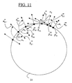
- the measuring points recorded successively on the circle ( p k1 , p k2, etc.).
- the probe (9) is in this case at the first measuring point ( p k1 ) at rest and is then accelerated to its high measuring speed (v s ).
- the probe (9) then gradually reaches its high measuring speed (v s ), the acceleration vectors rotate more and more in the radial direction, because on the one hand, the proportion of tangential Anfahrbeuggung is always lower and on the other side, the radial acceleration alsgund the curved Train increased more and more.
- the probe (9) has then reached the high measuring speed (v s ), so that the acceleration vectors ( b k6 , b k7 etc.) now parallel to the normal vectors ( n k6 , n k7, etc.). Only now does the acceleration due to the curved path in the normal direction, so that only now the recorded measuring points can be used meaningfully for calibration.
- the angle ( ⁇ i ) between the respective normal vectors and the acceleration vectors is evaluated.
- the angles ( ⁇ 1 , ⁇ 2 ) here about 90 °.
- the angles ( ⁇ 6 , ⁇ 7 ) are approximately 180 °.
- the check can be carried out, for example, in such a way that only measuring points in which the relevant angle (
- the just-described data validation can of course completely analogous with the Measured measured values with respect to the force applied to the workpiece measuring force be performed.
- the angle between the Meßkraftvektor and the to form the relevant normal vector is the angle between the Meßkraftvektor and the to form the relevant normal vector.
- the data validation described should be used both in the calibration of the dynamics tensors be used, as in the later measurement.
- Equation 9 The unknown coefficients (d sij ) of the matrix (D s ) in Equation 9 are determined by least-squares optimization.
- the calculation of the three coefficients of the antisymmetric matrix (D a ) proceeds - based on the theoretical model - essentially according to the same scheme with a calibration cube (23) with flat calibration surfaces which are parallel to the coordinate planes, that is to the xy plane, aligned to the xz plane and the yz plane.
- the evaluation of extensive test measurements has shown that the full dynamic correction for the measurement of flat surfaces in any spatial orientation is not possible. However, on the other hand, it is not necessary in this generality since a probe of a certain configuration is used for the measurement of planar workpiece surfaces. The correction and consequently the dynamic calibration is then sufficient for the current spatial orientation. This restriction is equivalent to the calibration of only two antisymmetric coefficients of (D a ) on a flat surface with the respective spatial orientation.
- FIG. 10 The measuring arrangement and the model approach for the calibration is shown in FIG. 10.
- the plane (25) of a cube (23) is measured quasi-statically along a circular path (24), ie with a very low measuring speed (v l ).
- the diameter of the circular path (24) corresponds approximately to the diameter of the calibration ball (18).
- a balancing circle with the center point ( m a ) and radius (r a ) and a surface normal ( n a ) determined.
- the circular path is scanned at a high measuring speed (v s ).
- the obtained antisymmetric dynamic matrix (D * a ) is then to be transformed by equation 18 into the measuring coordinate system (x, y, z).
- the resulting dynamic matrix (D) is then obtained by adding the three components (D 0 , D s and D a ) according to Equation 7.
- the calibration can also be aborted after the first or second stage, in which case residual errors remain.
- This allows the user to select the probe calibration depending on the measurement task. For example, in a measurement task in which almost no tangential deviation is to be expected, for example when measuring a bore, the antisymmetric torque matrix (D a ) can be dispensed with.
- the permissible measuring speed should be changed as a function of the dynamic stiffness which is stored in the calibrated dynamic tensor.
- the maximum permissible measuring speed (v max ) can be permitted up to a dynamic rigidity (C limit). Thereafter, the allowable measurement speed is reduced with decreasing stiffness in a transition region to (v min ). For stiffnesses smaller than (Cmin), either the measuring procedure is no longer executed or a corresponding message is output to the user.
- the measuring speed should also be changed depending on the mass of the stylus (13 or 16). As can be seen from FIG. 13, the maximum permissible measuring speed (v max ) can be permitted up to a stylus mass (m limit ). Thereafter, the permissible measuring speed is reduced with increasing stylus mass in a transition region to (v min ). For stylus masses greater than (m max ), either the measuring procedure is no longer executed or a corresponding message is output to the user.
Landscapes
- Physics & Mathematics (AREA)
- General Physics & Mathematics (AREA)
- A Measuring Device Byusing Mechanical Method (AREA)
- Length Measuring Devices With Unspecified Measuring Means (AREA)
Applications Claiming Priority (3)
| Application Number | Priority Date | Filing Date | Title |
|---|---|---|---|
| DE10025479 | 2000-05-23 | ||
| DE10025479 | 2000-05-23 | ||
| EP01112215A EP1158269B1 (fr) | 2000-05-23 | 2001-05-18 | Procédé pour corriger des appareils de mesure de coordonnées |
Related Parent Applications (1)
| Application Number | Title | Priority Date | Filing Date |
|---|---|---|---|
| EP01112215A Division EP1158269B1 (fr) | 2000-05-23 | 2001-05-18 | Procédé pour corriger des appareils de mesure de coordonnées |
Publications (2)
| Publication Number | Publication Date |
|---|---|
| EP1498691A1 true EP1498691A1 (fr) | 2005-01-19 |
| EP1498691B1 EP1498691B1 (fr) | 2009-08-12 |
Family
ID=7643230
Family Applications (2)
| Application Number | Title | Priority Date | Filing Date |
|---|---|---|---|
| EP01112215A Expired - Lifetime EP1158269B1 (fr) | 2000-05-23 | 2001-05-18 | Procédé pour corriger des appareils de mesure de coordonnées |
| EP04023526A Expired - Lifetime EP1498691B1 (fr) | 2000-05-23 | 2001-05-18 | Procédé pour corriger des appareils de mesure de coordonnées |
Family Applications Before (1)
| Application Number | Title | Priority Date | Filing Date |
|---|---|---|---|
| EP01112215A Expired - Lifetime EP1158269B1 (fr) | 2000-05-23 | 2001-05-18 | Procédé pour corriger des appareils de mesure de coordonnées |
Country Status (4)
| Country | Link |
|---|---|
| US (1) | US6591208B2 (fr) |
| EP (2) | EP1158269B1 (fr) |
| JP (1) | JP5022544B2 (fr) |
| DE (3) | DE50106760D1 (fr) |
Cited By (3)
| Publication number | Priority date | Publication date | Assignee | Title |
|---|---|---|---|---|
| WO2007122362A1 (fr) * | 2006-04-21 | 2007-11-01 | Renishaw Plc | Procédé de correction d'erreurs |
| WO2013007285A1 (fr) * | 2011-07-08 | 2013-01-17 | Carl Zeiss Industrielle Messtechnik Gmbh | Correction et/ou prévention d'erreurs lors de la mesure de coordonnées d'une pièce |
| DE102013216093A1 (de) * | 2013-08-14 | 2015-02-19 | Carl Zeiss Industrielle Messtechnik Gmbh | Reduzieren von Fehlern einer Drehvorrichtung, insbesondere für die Bestimmung von Koordinaten eines Werkstücks oder die Bearbeitung eines Werkstücks |
Families Citing this family (38)
| Publication number | Priority date | Publication date | Assignee | Title |
|---|---|---|---|---|
| GB0126232D0 (en) * | 2001-11-01 | 2002-01-02 | Renishaw Plc | Calibration of an analogue probe |
| DE10214489A1 (de) * | 2002-03-26 | 2003-10-23 | Zeiss Carl | Verfahren zur Bestimmung und Korrektur von Führungsfehlern bei einem Koordinatenmeßgerät |
| DE10229821B4 (de) * | 2002-06-28 | 2004-11-11 | Carl Zeiss | Koordinatenmeßgerät und Verfahren zur Steuerung eines Koordinatenmeßgerätes mit variabler Tastkopfmasse |
| DE10237501A1 (de) * | 2002-08-16 | 2004-03-04 | Carl Zeiss | Koordinatenmeßmaschine und Korrekturverfahren dafür |
| GB0326532D0 (en) * | 2003-11-13 | 2003-12-17 | Renishaw Plc | Method of error compensation |
| DE10360789B4 (de) * | 2003-12-23 | 2007-03-15 | Leuze Lumiflex Gmbh + Co. Kg | Vorrichtung zur Überwachung eines Erfassungsbereichs an einem Arbeitsmittel |
| DE102004020996A1 (de) | 2004-04-19 | 2005-11-03 | Carl Zeiss Industrielle Messtechnik Gmbh | Koordinatenmessgerät zum messtechnischen Bestimmen einer Koordinate an einem Messobjekt |
| DE102004038416B4 (de) * | 2004-07-30 | 2014-02-06 | Carl Zeiss Industrielle Messtechnik Gmbh | Verfahren zum Bestimmen von Raumkoordinaten eines Messpunktes an einem Messobjekt sowie entsprechendes Koordinatenmessgerät |
| GB0417536D0 (en) * | 2004-08-06 | 2004-09-08 | Renishaw Plc | The use of surface measurement probes |
| GB0508273D0 (en) * | 2005-04-25 | 2005-06-01 | Renishaw Plc | Method for scanning the surface of a workpiece |
| DE102005032749A1 (de) * | 2005-07-13 | 2007-01-18 | Carl Zeiss Industrielle Messtechnik Gmbh | Verfahren zum Antasten eines Werkstücks mit einem Koordinatenmessgerät und Koordinatenmessgeräte |
| GB0605796D0 (en) | 2006-03-23 | 2006-05-03 | Renishaw Plc | Apparatus and method of measuring workpieces |
| JP5221004B2 (ja) * | 2006-05-25 | 2013-06-26 | 株式会社ミツトヨ | 測定装置、表面性状測定方法、及び表面性状測定プログラム |
| JP5189806B2 (ja) * | 2006-09-07 | 2013-04-24 | 株式会社ミツトヨ | 表面形状測定装置 |
| FR2910136B1 (fr) | 2006-12-18 | 2009-02-27 | Essilor Int | Procede de correction de la geometrie d'une couche palpee approchant un brin longitudinal d'un drageoir de monture de lunettes et procede d'acquisition de la geometrie d'un contour d'un tel drageoir |
| WO2009001385A1 (fr) * | 2007-06-28 | 2008-12-31 | Hexagon Metrology S.P.A. | Procédé de détermination des erreurs dynamiques dans une machine de mesure |
| WO2009013769A1 (fr) * | 2007-07-24 | 2009-01-29 | Hexagon Metrology S.P.A. | Procédé permettant de compenser les erreurs de mesure provoquées par des déformations d'un banc de machine sous le poids d'une pièce usinée et machine de mesure fonctionnant selon ledit procédé |
| JP5192196B2 (ja) * | 2007-08-03 | 2013-05-08 | 株式会社ミツトヨ | 表面形状測定装置 |
| US7712224B2 (en) * | 2007-10-03 | 2010-05-11 | Hexagon Metrology Ab | Validating the error map of CMM using calibrated probe |
| DE102007051054A1 (de) | 2007-10-19 | 2009-04-30 | Carl Zeiss Industrielle Messtechnik Gmbh | Verfahren zum Korrigieren der Messwerte eines Koordinatenmessgeräts und Koordinatenmessgerät |
| DE102007057093A1 (de) * | 2007-11-20 | 2009-05-28 | Carl Zeiss Industrielle Messtechnik Gmbh | Verfahren zum Kalibrieren eines Koordinatenmessgerätes |
| DE102008024444B4 (de) | 2008-05-14 | 2020-07-09 | Carl Zeiss Industrielle Messtechnik Gmbh | Verfahren und Vorrichtung zum Kalibrieren eines Koordinatenmessgerätes |
| JP5612386B2 (ja) * | 2010-07-23 | 2014-10-22 | 株式会社ミツトヨ | 形状測定装置 |
| US9995574B2 (en) | 2011-08-11 | 2018-06-12 | Mitutoyo Corporation | CMM moving path adjustment assisting method and apparatus |
| US9222763B2 (en) * | 2012-03-02 | 2015-12-29 | Hexagon Metrology, Inc. | Coordinate measuring machine with constrained counterweight |
| DE102013101931B4 (de) | 2013-02-27 | 2022-02-03 | Carl Zeiss Industrielle Messtechnik Gmbh | Verfahren und Vorrichtung zum Vermessen eines Werkstücks |
| GB201311600D0 (en) * | 2013-06-28 | 2013-08-14 | Renishaw Plc | Calibration of a contact probe |
| JP6285146B2 (ja) * | 2013-10-29 | 2018-02-28 | 株式会社ミツトヨ | アーム型三次元測定機及びアーム型三次元測定機を支持する基部の傾斜補正方法 |
| JP6254456B2 (ja) * | 2014-02-21 | 2017-12-27 | 株式会社ミツトヨ | 三次元測定機及び三次元測定機による補正行列算出方法 |
| EP3034991B2 (fr) * | 2014-12-19 | 2022-08-24 | Hexagon Technology Center GmbH | Procédé et dispositif de compensation des forces de déplacement avec une unité de sonde |
| US9952044B2 (en) * | 2015-02-02 | 2018-04-24 | Rolls-Royce North American Technologies, Inc. | Multi-axis calibration block |
| DE102015109612B4 (de) | 2015-06-16 | 2020-08-13 | Carl Zeiss Industrielle Messtechnik Gmbh | Koordinatenmessgerät und Verfahren zum Kalibrieren desselben mit einer Time-of-Flight-Kamera |
| DE102015116850A1 (de) | 2015-10-05 | 2017-04-06 | Carl Zeiss Industrielle Messtechnik Gmbh | Überwachung eines sicherheitsrelevanten Parameters eines Koordinatenmessgeräts |
| DE102019122654A1 (de) * | 2019-08-22 | 2021-02-25 | M & H Inprocess Messtechnik Gmbh | Vorrichtung zur Kalibrierung einer Geschwindigkeit einer Bewegungsachse einer Maschine |
| DE102019220060A1 (de) * | 2019-12-18 | 2021-06-24 | Carl Zeiss Industrielle Messtechnik Gmbh | Verfahren zum Kalibrieren eines taktilen Sensors |
| DE102020204313A1 (de) | 2020-04-02 | 2021-10-07 | Carl Zeiss Industrielle Messtechnik Gmbh | Verfahren zum Kalibrieren eines Schwenktasters |
| DE102020207756A1 (de) | 2020-06-23 | 2020-08-06 | Carl Zeiss Industrielle Messtechnik Gmbh | Verfahren und Vorrichtung zur Bestimmung einer messeinrichtungsspezifischen Steifigkeit einer Koordinatenmesseinrichtung sowie Koordinatenmesseinrichtung |
| CN116793697A (zh) * | 2023-07-04 | 2023-09-22 | 中国航发沈阳发动机研究所 | 叶片机试验直角坐标移动探针测量发动机气流角修正方法 |
Citations (5)
| Publication number | Priority date | Publication date | Assignee | Title |
|---|---|---|---|---|
| US4333238A (en) | 1979-03-30 | 1982-06-08 | Mcmurtry David R | Coordinate measuring machine |
| US5007006A (en) * | 1987-03-06 | 1991-04-09 | Renishaw Plc | Method of and apparatus for calibration of machines |
| CH681913A5 (en) * | 1991-02-13 | 1993-06-15 | Roland Juillerat | Position error checking system for head on numerically controlled machine - includes rotary device with angular and radial sensors measuring displacement of head as it performs circular movement about axis |
| EP0684448A2 (fr) | 1994-05-27 | 1995-11-29 | Carl Zeiss | Procédé pour la mesure de coordonnées d'objets |
| US5610846A (en) * | 1994-05-27 | 1997-03-11 | Carl Zeiss Stiftung | Method for coordinate measurement on workpieces adjusted for bending of measuring apparatus structure |
Family Cites Families (11)
| Publication number | Priority date | Publication date | Assignee | Title |
|---|---|---|---|---|
| US4819195A (en) * | 1987-01-20 | 1989-04-04 | The Warner & Swasey Company | Method for calibrating a coordinate measuring machine and the like and system therefor |
| US4796195A (en) * | 1987-05-13 | 1989-01-03 | Cincinnati Milacron Inc. | Method for machining with improved accuracy |
| US5152072A (en) * | 1988-02-18 | 1992-10-06 | Renishaw Plc | Surface-sensing device |
| US5189806A (en) * | 1988-12-19 | 1993-03-02 | Renishaw Plc | Method of and apparatus for scanning the surface of a workpiece |
| DE4001433A1 (de) * | 1990-01-19 | 1991-07-25 | Zeiss Carl Fa | Korrekturverfahren fuer koordinatenmessgeraete |
| DE4245012B4 (de) * | 1992-04-14 | 2004-09-23 | Carl Zeiss | Verfahren zur Messung von Formelementen auf einem Koordinatenmeßgerät |
| JP3196145B2 (ja) * | 1992-04-30 | 2001-08-06 | 日本電信電話株式会社 | 加工・組立装置における接触点および接触法線検出法 |
| DE4436507A1 (de) * | 1994-10-13 | 1996-04-18 | Zeiss Carl Fa | Verfahren zur Koordinatenmessung an Werkstücken |
| US5832416A (en) * | 1995-09-01 | 1998-11-03 | Brown & Sharpe Manufacturing Company | Calibration system for coordinate measuring machine |
| DE59711571D1 (de) * | 1996-12-21 | 2004-06-03 | Zeiss Carl | Verfahren zur Steuerung von Koordinatenmessgeräten und Koordinatenmessgerät |
| DE19900724A1 (de) * | 1999-01-12 | 2000-07-27 | Zeiss Carl Fa | Koordinatenmeßgerät |
-
2001
- 2001-05-18 DE DE50106760T patent/DE50106760D1/de not_active Expired - Lifetime
- 2001-05-18 DE DE50115041T patent/DE50115041D1/de not_active Expired - Lifetime
- 2001-05-18 EP EP01112215A patent/EP1158269B1/fr not_active Expired - Lifetime
- 2001-05-18 EP EP04023526A patent/EP1498691B1/fr not_active Expired - Lifetime
- 2001-05-19 DE DE10124493A patent/DE10124493A1/de not_active Ceased
- 2001-05-23 US US09/862,321 patent/US6591208B2/en not_active Expired - Lifetime
- 2001-05-23 JP JP2001154588A patent/JP5022544B2/ja not_active Expired - Fee Related
Patent Citations (5)
| Publication number | Priority date | Publication date | Assignee | Title |
|---|---|---|---|---|
| US4333238A (en) | 1979-03-30 | 1982-06-08 | Mcmurtry David R | Coordinate measuring machine |
| US5007006A (en) * | 1987-03-06 | 1991-04-09 | Renishaw Plc | Method of and apparatus for calibration of machines |
| CH681913A5 (en) * | 1991-02-13 | 1993-06-15 | Roland Juillerat | Position error checking system for head on numerically controlled machine - includes rotary device with angular and radial sensors measuring displacement of head as it performs circular movement about axis |
| EP0684448A2 (fr) | 1994-05-27 | 1995-11-29 | Carl Zeiss | Procédé pour la mesure de coordonnées d'objets |
| US5610846A (en) * | 1994-05-27 | 1997-03-11 | Carl Zeiss Stiftung | Method for coordinate measurement on workpieces adjusted for bending of measuring apparatus structure |
Non-Patent Citations (1)
| Title |
|---|
| Q ET AL: "Error compensation of touch trigger probes", MEASUREMENT, INSTITUTE OF MEASUREMENT AND CONTROL. LONDON, GB, vol. 18, no. 1, 1 May 1996 (1996-05-01), pages 47 - 57, XP004040458, ISSN: 0263-2241 * |
Cited By (11)
| Publication number | Priority date | Publication date | Assignee | Title |
|---|---|---|---|---|
| WO2007122362A1 (fr) * | 2006-04-21 | 2007-11-01 | Renishaw Plc | Procédé de correction d'erreurs |
| CN101427100B (zh) * | 2006-04-21 | 2012-05-30 | 瑞尼斯豪公司 | 误差校正方法 |
| WO2013007285A1 (fr) * | 2011-07-08 | 2013-01-17 | Carl Zeiss Industrielle Messtechnik Gmbh | Correction et/ou prévention d'erreurs lors de la mesure de coordonnées d'une pièce |
| CN103782130A (zh) * | 2011-07-08 | 2014-05-07 | 卡尔蔡司工业测量技术有限公司 | 在测量工件的坐标时的误差修正和/或避免 |
| US20140167745A1 (en) * | 2011-07-08 | 2014-06-19 | Carl Zeiss Industrielle Messtechnik Gmbh | Correcting and/or preventing errors during the measurement of coordinates of a workpiece |
| US9671257B2 (en) | 2011-07-08 | 2017-06-06 | Carl Zeiss Industrielle Messtechnik Gmbh | Correcting and/or preventing errors during the measurement of coordinates of a workpiece |
| CN103782130B (zh) * | 2011-07-08 | 2017-06-20 | 卡尔蔡司工业测量技术有限公司 | 在测量工件的坐标时的误差修正和/或避免 |
| US10429178B2 (en) * | 2011-07-08 | 2019-10-01 | Carl Zeiss Industrielle Messtechnik Gmbh | Correcting and/or preventing errors during the measurement of coordinates of a work piece |
| DE102013216093A1 (de) * | 2013-08-14 | 2015-02-19 | Carl Zeiss Industrielle Messtechnik Gmbh | Reduzieren von Fehlern einer Drehvorrichtung, insbesondere für die Bestimmung von Koordinaten eines Werkstücks oder die Bearbeitung eines Werkstücks |
| DE102013216093B4 (de) * | 2013-08-14 | 2016-06-02 | Carl Zeiss Industrielle Messtechnik Gmbh | Reduzieren von Fehlern einer Drehvorrichtung, insbesondere für die Bestimmung von Koordinaten eines Werkstücks oder die Bearbeitung eines Werkstücks |
| US10073435B2 (en) | 2013-08-14 | 2018-09-11 | Carl Zeiss Industrielle Messtechnik Gmbh | Reducing errors of a rotatory device, in particular for the determination of coordinates of a workpiece or the machining of a workpiece |
Also Published As
| Publication number | Publication date |
|---|---|
| EP1158269A2 (fr) | 2001-11-28 |
| EP1498691B1 (fr) | 2009-08-12 |
| US20020029119A1 (en) | 2002-03-07 |
| DE50106760D1 (de) | 2005-08-25 |
| DE50115041D1 (de) | 2009-09-24 |
| US6591208B2 (en) | 2003-07-08 |
| EP1158269A3 (fr) | 2002-06-26 |
| JP2002022435A (ja) | 2002-01-23 |
| EP1158269B1 (fr) | 2005-07-20 |
| DE10124493A1 (de) | 2001-11-29 |
| JP5022544B2 (ja) | 2012-09-12 |
Similar Documents
| Publication | Publication Date | Title |
|---|---|---|
| EP1158269B1 (fr) | Procédé pour corriger des appareils de mesure de coordonnées | |
| EP2201328B1 (fr) | Procédé pour corriger les valeurs de mesure d'un appareil de mesure de coordonnées et appareil de mesure de coordonnées | |
| EP0684447B1 (fr) | Mesure de coordonnées d'objets avec correction du compartement en flexion de la machine de mesure de coordonnées qui est dépendant de la force de mesure | |
| EP2834595B1 (fr) | Méthode et appareil pour la réduction des erreurs associées à un dispositif de rotation lors de la détermination des coordonnées d'une pièce ou lors de l'usinage d'une pièce | |
| DE60019219T2 (de) | Verfahren zur kalibrierung eines scan-systems | |
| EP2331907B1 (fr) | Procédé de mesure d'une pièce et appareil de mesure de coordonnées | |
| DE60018412T2 (de) | Steuergerät für messinstrument | |
| EP2212647A1 (fr) | Procédé de calibrage d'un appareil de mesure de coordonnées | |
| DE4436507A1 (de) | Verfahren zur Koordinatenmessung an Werkstücken | |
| DE102020206719A1 (de) | Positionsmessverfahren und Positionsmesssystem für ein Objekt in einer Werkzeugmaschine | |
| DE29624373U1 (de) | Koordinationsmeßgerät zur Koordinatenmessung an Werkstücken | |
| EP1627203B1 (fr) | Procede d'etalonnage d'un palpeur | |
| DE602005005839T2 (de) | Verwendung von oberflächenmesssonden | |
| DE3781674T2 (de) | Positionsbestimmungsverfahren innerhalb des messraumes eines koordinatenmessgeraetes und dergleichen und system dafuer. | |
| DE19809589B4 (de) | Verfahren zur Kalibrierung eines Tasters eines Koordinatenmeßgerätes | |
| DE102020212982A1 (de) | Verfahren zur Verringerung von Messfehlern eines Koordinatenmessgeräts und Koordinatenmessgerät | |
| EP1391684B1 (fr) | Machine de mesure de coordonnées et méthode de correction d'erreur | |
| DE60032635T2 (de) | Verfahren und vorrichtung zum testen von werkzeugmaschinen | |
| DE102008063236B4 (de) | Verfahren zum Kalibrieren einer Messkraft an einem Koordinatenmessgerät | |
| EP2124116B1 (fr) | Procédé de commande d'un appareil de mesure des coordonnées à commande numérique assistée par ordinateur et appareil de mesure de coordonnées | |
| EP0613573B1 (fr) | Procede permettant de verifier la precision d'une machine a commande numerique | |
| DE102020208567B4 (de) | Kalibrieren eines Referenzkörpers für die Führungsfehlerermittlung einer Maschinenachse | |
| DE10136559B4 (de) | Verfahren zum Diagnostizieren von Schäden in einem messenden Tastkopf eines Koordinatenmessgeräts | |
| DE102020204313A1 (de) | Verfahren zum Kalibrieren eines Schwenktasters | |
| DE102016226087B4 (de) | Dreh-Schwenk-Sensorsystem für ein Koordinatenmessgerät |
Legal Events
| Date | Code | Title | Description |
|---|---|---|---|
| PUAI | Public reference made under article 153(3) epc to a published international application that has entered the european phase |
Free format text: ORIGINAL CODE: 0009012 |
|
| 17P | Request for examination filed |
Effective date: 20041002 |
|
| AC | Divisional application: reference to earlier application |
Ref document number: 1158269 Country of ref document: EP Kind code of ref document: P |
|
| AK | Designated contracting states |
Kind code of ref document: A1 Designated state(s): DE FR GB IT |
|
| AKX | Designation fees paid |
Designated state(s): DE FR GB IT |
|
| 17Q | First examination report despatched |
Effective date: 20080724 |
|
| GRAP | Despatch of communication of intention to grant a patent |
Free format text: ORIGINAL CODE: EPIDOSNIGR1 |
|
| GRAS | Grant fee paid |
Free format text: ORIGINAL CODE: EPIDOSNIGR3 |
|
| GRAA | (expected) grant |
Free format text: ORIGINAL CODE: 0009210 |
|
| AC | Divisional application: reference to earlier application |
Ref document number: 1158269 Country of ref document: EP Kind code of ref document: P |
|
| AK | Designated contracting states |
Kind code of ref document: B1 Designated state(s): DE FR GB IT |
|
| REG | Reference to a national code |
Ref country code: GB Ref legal event code: FG4D Free format text: NOT ENGLISH |
|
| REF | Corresponds to: |
Ref document number: 50115041 Country of ref document: DE Date of ref document: 20090924 Kind code of ref document: P |
|
| PLBE | No opposition filed within time limit |
Free format text: ORIGINAL CODE: 0009261 |
|
| STAA | Information on the status of an ep patent application or granted ep patent |
Free format text: STATUS: NO OPPOSITION FILED WITHIN TIME LIMIT |
|
| 26N | No opposition filed |
Effective date: 20100517 |
|
| PGFP | Annual fee paid to national office [announced via postgrant information from national office to epo] |
Ref country code: FR Payment date: 20130603 Year of fee payment: 13 |
|
| REG | Reference to a national code |
Ref country code: FR Ref legal event code: ST Effective date: 20150130 |
|
| PG25 | Lapsed in a contracting state [announced via postgrant information from national office to epo] |
Ref country code: FR Free format text: LAPSE BECAUSE OF NON-PAYMENT OF DUE FEES Effective date: 20140602 |
|
| PGFP | Annual fee paid to national office [announced via postgrant information from national office to epo] |
Ref country code: GB Payment date: 20170519 Year of fee payment: 17 |
|
| PGFP | Annual fee paid to national office [announced via postgrant information from national office to epo] |
Ref country code: IT Payment date: 20170526 Year of fee payment: 17 |
|
| GBPC | Gb: european patent ceased through non-payment of renewal fee |
Effective date: 20180518 |
|
| PG25 | Lapsed in a contracting state [announced via postgrant information from national office to epo] |
Ref country code: IT Free format text: LAPSE BECAUSE OF NON-PAYMENT OF DUE FEES Effective date: 20180518 Ref country code: GB Free format text: LAPSE BECAUSE OF NON-PAYMENT OF DUE FEES Effective date: 20180518 |
|
| PGFP | Annual fee paid to national office [announced via postgrant information from national office to epo] |
Ref country code: DE Payment date: 20200520 Year of fee payment: 20 |
|
| REG | Reference to a national code |
Ref country code: DE Ref legal event code: R071 Ref document number: 50115041 Country of ref document: DE |