EP1498703B1 - Vorrichtung zur Schätzung des Insassengewichts eines Kraftfahrzeuges - Google Patents
Vorrichtung zur Schätzung des Insassengewichts eines Kraftfahrzeuges Download PDFInfo
- Publication number
- EP1498703B1 EP1498703B1 EP04076921A EP04076921A EP1498703B1 EP 1498703 B1 EP1498703 B1 EP 1498703B1 EP 04076921 A EP04076921 A EP 04076921A EP 04076921 A EP04076921 A EP 04076921A EP 1498703 B1 EP1498703 B1 EP 1498703B1
- Authority
- EP
- European Patent Office
- Prior art keywords
- seat
- slider member
- floor
- coupled
- bracket
- Prior art date
- Legal status (The legal status is an assumption and is not a legal conclusion. Google has not performed a legal analysis and makes no representation as to the accuracy of the status listed.)
- Expired - Lifetime
Links
- 238000006243 chemical reaction Methods 0.000 claims description 2
- 238000004873 anchoring Methods 0.000 claims 1
- 230000036316 preload Effects 0.000 abstract description 5
- 238000001514 detection method Methods 0.000 abstract description 4
- 230000002452 interceptive effect Effects 0.000 abstract description 2
- 238000005259 measurement Methods 0.000 abstract description 2
- 230000000712 assembly Effects 0.000 description 10
- 238000000429 assembly Methods 0.000 description 10
- 230000007246 mechanism Effects 0.000 description 4
- 238000010586 diagram Methods 0.000 description 2
- 238000000034 method Methods 0.000 description 2
- 230000000153 supplemental effect Effects 0.000 description 2
- 208000027418 Wounds and injury Diseases 0.000 description 1
- 238000009530 blood pressure measurement Methods 0.000 description 1
- 230000008878 coupling Effects 0.000 description 1
- 238000010168 coupling process Methods 0.000 description 1
- 238000005859 coupling reaction Methods 0.000 description 1
- 230000006378 damage Effects 0.000 description 1
- 239000012530 fluid Substances 0.000 description 1
- 208000014674 injury Diseases 0.000 description 1
- 238000012986 modification Methods 0.000 description 1
- 230000004048 modification Effects 0.000 description 1
Images

Classifications
-
- B—PERFORMING OPERATIONS; TRANSPORTING
- B60—VEHICLES IN GENERAL
- B60R—VEHICLES, VEHICLE FITTINGS, OR VEHICLE PARTS, NOT OTHERWISE PROVIDED FOR
- B60R21/00—Arrangements or fittings on vehicles for protecting or preventing injuries to occupants or pedestrians in case of accidents or other traffic risks
- B60R21/01—Electrical circuits for triggering passive safety arrangements, e.g. airbags, safety belt tighteners, in case of vehicle accidents or impending vehicle accidents
- B60R21/015—Electrical circuits for triggering passive safety arrangements, e.g. airbags, safety belt tighteners, in case of vehicle accidents or impending vehicle accidents including means for detecting the presence or position of passengers, passenger seats or child seats, and the related safety parameters therefor, e.g. speed or timing of airbag inflation in relation to occupant position or seat belt use
- B60R21/01512—Passenger detection systems
- B60R21/01516—Passenger detection systems using force or pressure sensing means
- B60R21/0152—Passenger detection systems using force or pressure sensing means using strain gauges
-
- G—PHYSICS
- G01—MEASURING; TESTING
- G01G—WEIGHING
- G01G19/00—Weighing apparatus or methods adapted for special purposes not provided for in the preceding groups
- G01G19/40—Weighing apparatus or methods adapted for special purposes not provided for in the preceding groups with provisions for indicating, recording, or computing price or other quantities dependent on the weight
- G01G19/413—Weighing apparatus or methods adapted for special purposes not provided for in the preceding groups with provisions for indicating, recording, or computing price or other quantities dependent on the weight using electromechanical or electronic computing means
- G01G19/414—Weighing apparatus or methods adapted for special purposes not provided for in the preceding groups with provisions for indicating, recording, or computing price or other quantities dependent on the weight using electromechanical or electronic computing means using electronic computing means only
- G01G19/4142—Weighing apparatus or methods adapted for special purposes not provided for in the preceding groups with provisions for indicating, recording, or computing price or other quantities dependent on the weight using electromechanical or electronic computing means using electronic computing means only for controlling activation of safety devices, e.g. airbag systems
Definitions
- This invention is directed to apparatus for detecting the weight of an occupant of a motor vehicle seat for purposes of determining whether and how forcefully to deploy supplemental restraints, and more particularly to apparatus for measuring forces applied to a frame of the vehicle seat.
- Vehicle occupant detection systems are useful in connection with air bags and other pyrotechnically deployed restraints as a means of judging whether, and how forcefully, to deploy the restraint.
- One fundamental parameter in this regard is the weight of the occupant, as weight may be used as a criterion to distinguish between an adult and an infant or small child.
- the occupant weight may be measured with one or more load cells that sense the forces (strain or pressure) that the seat applies to a bracket that supports the seat on the vehicle floor. See, for example, the Publication Nos. 41520, 41542, 41549 and 41559 from the November, 1998 issue of Research Disclosure. Since the "frame-based" load cell configurations become part of the supporting structure of the seat, they tend to be relatively bulky and/or expensive to produce. Accordingly, what is needed is a frame-based occupant weight estimation apparatus that is simple and inexpensive to produce, and that does not compromise the structural integrity of the seat.
- EP-A-0950560 discloses apparatus in accordance with the preamble of claim 1.
- EP-A-0955203 discloses a load sensing mount for a seat in which a bolt shank engages a resilient plate, and a strain sensor is secured to the plate.
- the present invention is directed to an improved frame-based occupant weight estimation apparatus for a vehicle seat, including compliant linkage assemblies interposed between the seat frame and floor brackets bolted to the vehicle floor.
- compliant linkage assemblies translate vertically applied seat loads to a horizontal plane (that is, parallel to the vehicle floor), where the horizontal forces are measured by a set of force sensors.
- a compliant member which may a spring or a linkage arm, preloads the force sensor to enable off-loading detection, and an overload device securely anchors the seat to the floor bracket without interfering with normal load measurement.
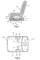
- the reference numeral 10 generally designates a vehicle seat, including seat and backrest cushions 10a, 10b supported on a frame including a set of mounting brackets 12.
- the seat 10 is secured to the vehicle floor 14 by a pair of laterally spaced floor brackets 16, 18 that are bolted to floor 14, and a set of linkage assemblies 20 are interposed between the seat frame mounting brackets 12 and the floor brackets 16, 18 for supporting the seat 10 and estimating the weight of a seat occupant.
- the illustrated embodiment there are four seat mounting brackets (left front, right front, left rear and right rear) and four associated linkage assemblies, but only the left-front and left-rear seat mounting brackets 12, 12' and the left-front and left-rear linkage mechanisms 20, 20' are visible in the drawings.
- the front and rear linkage assemblies 20, 20' are mirror image but otherwise identical; accordingly the following description of the linkage assembly 20 applies equally to linkage assembly 20' as well as the right-front and right-rear linkage assemblies.
- the linkage assembly 20 includes first and second linkage arms 22 and 24 rotatably coupled at one end to a pin 26 secured to the seat frame mounting bracket 12.
- the other end of arm 22 is rotatably coupled to a pin 28 secured in a mounting bracket 30 of floor bracket 16, and the other end of arm 24 is rotatably coupled to a pin 32 secured to a slider block 34 that is supported on the base of floor bracket 16 for linear movement substantially parallel to the vehicle floor.
- the weight of the seat 10 and a spring 36 bias the slider block 34 into engagement with a force sensor 38 which is disposed between slider block 34 and a central post 40 of floor bracket 16.
- the force sensor 38 may be a strain gauge device or load cell such as those produced and sold by Panasonic Corporation or Texas Instruments Corporation, and produces an electrical output signal functionally related to the force applied to it by slider block 34.
- the bias or preload force applied to force sensor 38 is particularly important in frame-based occupant weight estimation because it enables off-loading detection. This can occur, for example, when the occupant leans back in the seat 10, reducing the force measured by the linkage assemblies coupled to mounting brackets on the front of the seat 10. Due to the preload force, such off-loading can be measured and taken into consideration in the weight estimation calculations.
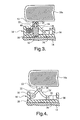
- Figure 2 depicts the force sensor layout for the embodiment of Figure 1 , with the force sensors 38a and 38b being disposed in the floor bracket 16, and the force sensors 38c and 38d being disposed in the floor bracket 18.
- the co-located sensors 38a, 38b are electrically coupled to a first connector 42, while the co-located sensors 38c, 38d are electrically coupled to a second connector 44.
- the connectors 42 and 44 are electrically coupled to a microcontroller (uC) 46, which may be located beneath the seat 10 as shown or at a remote location.
- UIC microcontroller
- the microcontroller 46 processes the output signals produced by the sensors 38a, 38b, 38c, 38d to determine corresponding weights attributable to a seat occupant, and sums the weights to determine the occupant weight or weight classification for purposes of deciding whether and how forcefully to deploy supplemental restraints designed to protect the occupant from serious injury in a crash event.
- Figure 3 depicts an alternate embodiment in which a spiral torsion spring 48 is used in place of the linear coil spring 36 of Figure 1 .
- the spring 48 imparts a moment to the arm 22 which tends to make the arms 22 and 24 co-linear.
- Figure 3 depicts an overload plate 50 for limiting upward movement of the seat 10a with respect to the floor brackets 16, 18 in the event of a crash.
- overload plates are preferably installed at each of the four seat frame mounting brackets 12, 12'.
- the plate 50 is anchored on a post 52 formed on floor bracket 16, and has an elongated aperture 54 through which the pin 26 extends.
- the pin 26 does not contact the plate 50 in normal operation, but contacts the plate 50 when a strong upward force is applied to seat 10.
- the plate 50 is applicable to each of the various embodiments depicted herein, but has been omitted from the other embodiments so as not to obscure the linkage mechanism elements.
- Figure 4 depicts an alternate embodiment in which the arm 24' of linkage assembly 20 is compliant instead of rigid.
- the arm 24' biases the slider block 34 against the sensor 38, and no external spring is required.
- the arm 22 could be compliant instead of, or in addition to, the arm 24', if desired.
- Figure 5 depicts an alternate embodiment in which the linkage assembly 20 includes two additional arms 60 and 62.
- the arms 60 and 62 are rotatably co-joined at pin 64, the arm 60 also being rotatably coupled to the pin 28 of floor bracket 16, and the arm 62 also being rotatably coupled to the pin 32 of slider block 34.
- This arrangement requires additional space under the seat 10, but reduces frictional losses.
- one or more of the bars 22, 24, 60, 62 can be compliant to provide the desired bias or preload on sensor 38, or the bias can be provided by an external spring as shown in Figures 1 and 3 .
- Figure 6 depicts an alternate embodiment in which the linkage assembly 20 is a compliant one-piece device that applies a compressive force to the sensor 38 in relation to occupant weight.
- the device 20 includes first and second lever arms 70 and 72 rotatably coupled to the pins 26 and 28 of seat frame mounting bracket 12 and floor bracket 16.
- the lever arms 70 and 72 are joined at a fulcrum which defines the slider block 74, and a circumferential arm 76 joined to the lever arms 70 and 72 provides a reaction surface 78 for the force sensor 38.
- the present invention provides a seat frame-based occupant weight estimation apparatus including a compliant linkage assembly that translates vertical force associated with occupant weight to a horizontal force that is sensed by a pre-loaded force sensor.
- the several different embodiments each include a linkage mechanism coupling the seat mounting bracket to a floor bracket, and an overload mechanism for limiting upward movement of the seat with respect to the floor bracket.
- Each linkage assembly includes a slider block that exerts a compressive force on the respective force sensor, and the sum of the measured forces is indicative of occupant weight.
- the linkage assemblies depicted in Figures 1 , 3 , 4 and 5 can be configured in accordance with the teachings of U.S. Patent No. 5,649,454 , co-assigned to Purdue Research Foundation and the assignee of the with the path of movement of slider block 34, and the length of the linkage arms should be designed so that the bias force is substantially constant for any position of the arms 22, 24.
- a detailed description of the linkage arm dimensional considerations is set forth in the aforementioned U.S. Patent No. 5,649,454 .
- the seat 10 may be supported by a greater or lesser number of linkage assemblies, the linkage assemblies may be oriented laterally with respect to the seat 10,and so on.
Landscapes
- Engineering & Computer Science (AREA)
- Physics & Mathematics (AREA)
- Mathematical Physics (AREA)
- Theoretical Computer Science (AREA)
- Mechanical Engineering (AREA)
- General Physics & Mathematics (AREA)
- Seats For Vehicles (AREA)
- Air Bags (AREA)
- Force Measurement Appropriate To Specific Purposes (AREA)
- Electric Propulsion And Braking For Vehicles (AREA)
Claims (12)
- Vorrichtung zum Schätzen des Gewichts eines Insassen eines Fahrzeugsitzes (10), der durch eine Bodenhalterung (16) getragen wird, die auf einem Fahrzeugboden (14) befestigt ist, wobei die Vorrichtung aufweist:einen Kraft-Sensor (38); undeinen nachgiebigen Verbindungsaufbau (20), der zwischen der Bodenhalterung (16) und einer Befestigungshalterung (12) des Sitzes (10) eingefügt ist, mit Verbindungsarmen (22, 24), die rotierbar mit der Bodenhalterung (16) und der Befestigungshalterung (12) verbunden sind, gekennzeichnet durch ein Schiebelement (34), das für eine lineare Bewegung im Wesentlichen parallel zu dem Fahrzeugboden (14) gelagert ist, und Mittel (36, 48, 24') zum Beeinflussen des Schiebelements (34) in einen Eingriff mit dem Kraft-Sensor (38), wobei die Verbindungsarme (22, 24) mit dem Schiebelement (34) derart verbunden sind, dass ein Insassengewicht, das auf den Sitz (10) angewendet wird, eine lineare Bewegung des Schiebelements (34) erzeugt, die eine Eingriffskraft zwischen dem Schiebelement (34) und dem Kraft-Sensor (38) erhöht, wobei der Kraft-Sensor (38) ein Ausgabesignal erzeugt, das das Insassengewicht anzeigt.
- Vorrichtung gemäß Anspruch 1, wobei das Mittel zum Beeinflussen des Schiebelemente (34) in Eingriff mit dem Kraft-Sensor (38) eine Feder (36, 48) umfasst.
- Vorrichtung gemäß Anspruch 2, wobei die Feder eine Spiralfeder (36) ist, die eine lineare Bias-Kraft im Wesentlichen parallel zu dem Fahrzeugboden (14) anwendet.
- Vorrichtung gemäß Anspruch 2, wobei die Feder eine Torsionsfeder (48) ist, die mit zumindest einem der Verbindungsarme (22) verbunden ist.
- Vorrichtung gemäß Anspruch 1, wobei die Verbindungsarme einen ersten Arm (22) umfassen, der zwischen der Sitz-Befestigungshalterung (12) und der Bodenhalterung (16) verbunden ist, und einen zweiten Arm (24), der zwischen der Sitz-Befestigungshalterung (12) und dem Schiebelement (34) verbunden ist, und wobei das Mittel (36, 48, 24') zum Beeinflussen des Schiebelements (34) in einen Eingriff mit dem Kraft-Sensor (38) auch die ersten und zweiten Arme kollinear zu der linearen Bewegung des Schiebelements (34) bringt.
- Vorrichtung gemäß Anspruch 5, wobei das Mittel zum Beeinflussen des Schiebelements (34) in einen Eingriff mit dem Kraft-Sensor (38) einen Nullzustand hat, wenn die Verbindungsarme (22, 24) mit der linearen Bewegung des Schiebelements (34) kollinear sind, und wobei die Verbindungsarme (22, 24) Längen haben derart, dass die Bias-Kraft für jede Position der Verbindungsarme (22, 24) im Wesentlichen konstant ist.
- Vorrichtung gemäß Anspruch 1, wobei die Verbindungsarme einen ersten Arm (22) umfassen, der zwischen der Sitz-Befestigungshalterung (12) und der Bodenhalterung (16) verbunden ist, und einen zweiten Arm (24'), der zwischen der Sitz-Befestigungshalterung (12) und dem Schiebelement (34) verbunden ist, und wobei zumindest einer der ersten und zweiten Verbindungsarme (24') nachgiebig ist zum Beeinflussen des Schiebelements (34) in einen Eingriff mit dem Kraft-Sensor (38).
- Vorrichtung gemäß Anspruch 1, wobei der Verbindungsaufbau (20) Überlastungsmittel (50) umfasst zum Befestigen des Sitzes (10) an der Bodenhalterung (16), um zu verhindern, dass der Sitz (10) von der Bodenhalterung (16) losgelöst wird.
- Vorrichtung gemäß Anspruch 1, wobei die Verbindungsarme einen ersten Arm (22) umfassen, der zwischen der Sitz-Befestigungshalterung (12) und der Bodenhalterung (16) verbunden ist, einen zweiten Arm (24), der zwischen der Sitz-Befestigungshalterung (12) und dem Schiebelement (34) verbunden ist, und dritte und vierte ebenfalls verbundene Arme (60, 62), die zwischen der Bodenhalterung (16) und dem Schiebelement (34) verbunden sind.
- Vorrichtung gemäß Anspruch 1, wobei der Verbindungsaufbau (20) definiert ist durch eine nachgiebige Vorrichtung mit ersten und zweiten Hebelarmen (70, 72), die rotierbar mit der Sitz-Befestigungshalterung (12) und der Bodenhalterung (16) verbunden sind, wobei die Hebelarme (70, 72) an einem Drehpunkt (74) verbunden sind, der den Schiebeblock (34) definiert.
- Vorrichtung gemäß Anspruch 10, wobei die nachgiebige Vorrichtung einen Umfangsarm (76) umfasst, der die ersten und zweiten Hebelarme (70, 72) verbindet zu einer Reaktionsfläche (78) für den Kraft-Sensor (38).
- Vorrichtung gemäß Anspruch 1, wobei der Sitz (10) einen Satz von Befestigungshalterungen (12) umfasst, und die Vorrichtung einen Kraft-Sensor (38a, 38b, 38c, 38d) und einen nachgiebigen Verbindungsaufbau (20, 20') für jede derartige Sitz-Befestigungshalterung (12) umfasst, und die Kraft-Sensoren (38a, 38b, 38c, 38d) in Paaren angeordnet sind, um elektrische Anschlüsse mit den Kraft-Sensoren (38a, 38b, 38c, 38d) zu erleichtern.
Applications Claiming Priority (2)
| Application Number | Priority Date | Filing Date | Title |
|---|---|---|---|
| US618905 | 2003-07-14 | ||
| US10/618,905 US6987229B2 (en) | 2003-07-14 | 2003-07-14 | Frame-based occupant weight estimation apparatus having compliant linkage assembly |
Publications (3)
| Publication Number | Publication Date |
|---|---|
| EP1498703A2 EP1498703A2 (de) | 2005-01-19 |
| EP1498703A3 EP1498703A3 (de) | 2006-10-25 |
| EP1498703B1 true EP1498703B1 (de) | 2010-03-17 |
Family
ID=33477064
Family Applications (1)
| Application Number | Title | Priority Date | Filing Date |
|---|---|---|---|
| EP04076921A Expired - Lifetime EP1498703B1 (de) | 2003-07-14 | 2004-07-02 | Vorrichtung zur Schätzung des Insassengewichts eines Kraftfahrzeuges |
Country Status (4)
| Country | Link |
|---|---|
| US (1) | US6987229B2 (de) |
| EP (1) | EP1498703B1 (de) |
| AT (1) | ATE461435T1 (de) |
| DE (1) | DE602004026011D1 (de) |
Families Citing this family (16)
| Publication number | Priority date | Publication date | Assignee | Title |
|---|---|---|---|---|
| US20050184496A1 (en) * | 2003-10-03 | 2005-08-25 | Speckhart Frank H. | Sensor pad for controlling airbag deployment and associated support |
| US7657128B2 (en) | 2000-05-23 | 2010-02-02 | Silverbrook Research Pty Ltd | Optical force sensor |
| US7308347B2 (en) * | 2003-07-14 | 2007-12-11 | Delphi Technologies, Inc. | Frame-based occupant weight estimation apparatus having compliant load transfer mechanism |
| US7246850B2 (en) * | 2004-09-08 | 2007-07-24 | Tk Holdings Inc. | Seat weight sensor |
| US8546680B2 (en) * | 2005-07-08 | 2013-10-01 | Ying Wen Hsu | Energy efficient micro combustion system for power generation and fuel processing |
| US7928967B2 (en) | 2005-08-19 | 2011-04-19 | Silverbrook Research Pty Ltd | Force sensor with angled coupling |
| AU2006281960C1 (en) * | 2005-08-19 | 2010-01-07 | Silverbrook Research Pty Ltd | An electronic stylus with a force re-directing coupling |
| US20080136227A1 (en) * | 2006-12-11 | 2008-06-12 | 3M Innovative Properties Company | Vehicle seat sensor assembly |
| US20080319697A1 (en) * | 2007-06-19 | 2008-12-25 | Gray Charles A | System and method for determining an amount of pressure applied by an occupant on a vehicle seat |
| DE102008020865B4 (de) * | 2008-04-25 | 2010-02-18 | Grammer Ag | Fahrzeugsitz mit einer Einrichtung für eine Fahrzeugsitzbelegungserkennung |
| DE102008022046B3 (de) | 2008-05-03 | 2009-07-30 | Grammer Ag | Einrichtung für eine Fahrzeugsitzbelegungserkennung |
| US20100191390A1 (en) * | 2009-01-28 | 2010-07-29 | Delphi Technologies, Inc. | System and method for detecting the occupancy of a vehicle seat |
| EP2236346B1 (de) | 2009-04-02 | 2014-03-05 | Grammer Ag | Erkennungseinrichtung und Verfahren zum Erkennen einer Belegung eines Sitzes |
| CN102069648A (zh) * | 2009-11-23 | 2011-05-25 | 鸿富锦精密工业(深圳)有限公司 | 纸盘固定装置及打印机 |
| US10988095B2 (en) * | 2019-04-26 | 2021-04-27 | Yefim G. Kriger | Adaptive multi-force safety system (ADMUS) |
| US11719557B2 (en) | 2019-12-24 | 2023-08-08 | Joyson Safety Systems Acquisition Llc | Apparatus and method of producing a sensing substrate |
Family Cites Families (18)
| Publication number | Priority date | Publication date | Assignee | Title |
|---|---|---|---|---|
| US5474327A (en) | 1995-01-10 | 1995-12-12 | Delco Electronics Corporation | Vehicle occupant restraint with seat pressure sensor |
| US6012007A (en) | 1995-12-01 | 2000-01-04 | Delphi Technologies, Inc. | Occupant detection method and apparatus for air bag system |
| US5987370A (en) | 1997-09-03 | 1999-11-16 | Delco Electronics Corp. | Vehicle occupant weight estimation apparatus having fluid-filled seat bladder |
| US5942695A (en) | 1997-12-22 | 1999-08-24 | Delco Electronics Corp | Method and apparatus for measuring seat loading by strain gauge |
| JP3655745B2 (ja) * | 1998-04-16 | 2005-06-02 | タカタ株式会社 | シート重量計測装置 |
| GB2337027B (en) * | 1998-05-05 | 2001-11-21 | Delco Electronic Europ Gmbh | Load sensing mounting for a vehicle seat |
| US6087598A (en) * | 1999-02-03 | 2000-07-11 | Trw Inc. | Weight sensing apparatus for vehicle seat |
| US6360618B2 (en) | 1999-06-10 | 2002-03-26 | Delphi Technologies, Inc. | Weight sensing system |
| US6246936B1 (en) | 1999-10-05 | 2001-06-12 | Delphi Technologies, Inc. | Vehicle occupant characterization method based on sensed occupant weight |
| US6424898B2 (en) | 2000-06-23 | 2002-07-23 | Delphi Technologies, Inc. | Vehicle occupant restraint control system using a crash severity model |
| US6448512B1 (en) * | 2000-08-22 | 2002-09-10 | Trw Inc. | Weight sensing apparatus |
| JP3991577B2 (ja) | 2000-11-07 | 2007-10-17 | 松下電器産業株式会社 | レバースイッチ |
| DE10120977A1 (de) * | 2001-05-01 | 2002-11-14 | Bizerba Gmbh & Co Kg | Fahrzeugsitz |
| US6542802B2 (en) | 2001-07-02 | 2003-04-01 | Delphi Technologies, Inc. | Vehicle occupant characterization method with rough road compensation |
| US6578871B2 (en) | 2001-10-09 | 2003-06-17 | Delphi Technologies, Inc. | Vehicle occupant weight detection system with occupant position compensation |
| US6587770B1 (en) | 2002-02-26 | 2003-07-01 | Delphi Technologies, Inc. | Vehicle seat occupant weight estimation method with floor weight compensation |
| US6438476B1 (en) | 2002-02-27 | 2002-08-20 | Delphi Technologies, Inc. | Vehicle seat occupant characterization method including ultralight child seat detection |
| US6438477B1 (en) | 2002-02-27 | 2002-08-20 | Delphi Technologies, Inc. | Vehicle seat occupant characterization method including empty seat detection |
-
2003
- 2003-07-14 US US10/618,905 patent/US6987229B2/en not_active Expired - Lifetime
-
2004
- 2004-07-02 AT AT04076921T patent/ATE461435T1/de not_active IP Right Cessation
- 2004-07-02 DE DE602004026011T patent/DE602004026011D1/de not_active Expired - Lifetime
- 2004-07-02 EP EP04076921A patent/EP1498703B1/de not_active Expired - Lifetime
Also Published As
| Publication number | Publication date |
|---|---|
| EP1498703A3 (de) | 2006-10-25 |
| DE602004026011D1 (de) | 2010-04-29 |
| EP1498703A2 (de) | 2005-01-19 |
| US6987229B2 (en) | 2006-01-17 |
| ATE461435T1 (de) | 2010-04-15 |
| US20050011682A1 (en) | 2005-01-20 |
Similar Documents
| Publication | Publication Date | Title |
|---|---|---|
| US6987229B2 (en) | Frame-based occupant weight estimation apparatus having compliant linkage assembly | |
| KR100925057B1 (ko) | 웨빙 장력 센서 | |
| US7132953B2 (en) | Spring sensor assembly for a vehicle seat cushion | |
| US7523679B2 (en) | Switch-based seat sensor for occupant presence detection | |
| US7143658B2 (en) | Deflection plate weight sensor for vehicle seat | |
| US6595570B2 (en) | Vehicle seat assembly having load cell based seat occupant sensing system | |
| US6912920B2 (en) | Frame-based occupant weight estimation load cell with ball-actuated force sensor | |
| KR20050014023A (ko) | 좌석 벨트 장력 센서 | |
| US6684718B2 (en) | Load detection structure for vehicle seat | |
| JP2004090717A (ja) | サイドエアバッグシステム | |
| EP1491387B1 (de) | Vorrichtung mit am Rahmen bezogener Blase zur Gewicht Ermittlung eines Sitzbenutzers | |
| EP1330379B1 (de) | Belastungssensor mit überlastungschutz für sicherheitsgurt | |
| US6561300B1 (en) | Vehicle seat having passenger detector | |
| US20050173904A1 (en) | Control system for vehicle occupant protection apparatus | |
| US7308347B2 (en) | Frame-based occupant weight estimation apparatus having compliant load transfer mechanism | |
| JP2004345362A (ja) | 重量計測システム、重量計測方法および荷重伝達リンク | |
| JP2004093232A (ja) | 乗員検知システム | |
| US20050061554A1 (en) | Torque-based occupant weight estimation apparatus for a vehicle seat | |
| EP0955203B1 (de) | Lastenfühleinrichtung für Fahrzeugsitze | |
| JP2002337588A (ja) | 乗員検出装置 | |
| JP2005254926A (ja) | 車両シート用荷重センサ及び車両シート | |
| KR20090028148A (ko) | 차량용 승객유형 감지장치 | |
| KR20210039004A (ko) | 착석감지 시스템을 가진 자동차 시트 | |
| HK1053167A1 (en) | Seat weight measurement system |
Legal Events
| Date | Code | Title | Description |
|---|---|---|---|
| PUAI | Public reference made under article 153(3) epc to a published international application that has entered the european phase |
Free format text: ORIGINAL CODE: 0009012 |
|
| AK | Designated contracting states |
Kind code of ref document: A2 Designated state(s): AT BE BG CH CY CZ DE DK EE ES FI FR GB GR HU IE IT LI LU MC NL PL PT RO SE SI SK TR |
|
| AX | Request for extension of the european patent |
Extension state: AL HR LT LV MK |
|
| PUAL | Search report despatched |
Free format text: ORIGINAL CODE: 0009013 |
|
| AK | Designated contracting states |
Kind code of ref document: A3 Designated state(s): AT BE BG CH CY CZ DE DK EE ES FI FR GB GR HU IE IT LI LU MC NL PL PT RO SE SI SK TR |
|
| AX | Request for extension of the european patent |
Extension state: AL HR LT LV MK |
|
| 17P | Request for examination filed |
Effective date: 20070425 |
|
| AKX | Designation fees paid |
Designated state(s): AT BE BG CH CY CZ DE DK EE ES FI FR GB GR HU IE IT LI LU MC NL PL PT RO SE SI SK TR |
|
| 17Q | First examination report despatched |
Effective date: 20071105 |
|
| GRAP | Despatch of communication of intention to grant a patent |
Free format text: ORIGINAL CODE: EPIDOSNIGR1 |
|
| GRAS | Grant fee paid |
Free format text: ORIGINAL CODE: EPIDOSNIGR3 |
|
| GRAA | (expected) grant |
Free format text: ORIGINAL CODE: 0009210 |
|
| AK | Designated contracting states |
Kind code of ref document: B1 Designated state(s): AT BE BG CH CY CZ DE DK EE ES FI FR GB GR HU IE IT LI LU MC NL PL PT RO SE SI SK TR |
|
| REG | Reference to a national code |
Ref country code: GB Ref legal event code: FG4D |
|
| REG | Reference to a national code |
Ref country code: CH Ref legal event code: EP |
|
| REG | Reference to a national code |
Ref country code: IE Ref legal event code: FG4D |
|
| REF | Corresponds to: |
Ref document number: 602004026011 Country of ref document: DE Date of ref document: 20100429 Kind code of ref document: P |
|
| REG | Reference to a national code |
Ref country code: NL Ref legal event code: VDEP Effective date: 20100317 |
|
| PG25 | Lapsed in a contracting state [announced via postgrant information from national office to epo] |
Ref country code: FI Free format text: LAPSE BECAUSE OF FAILURE TO SUBMIT A TRANSLATION OF THE DESCRIPTION OR TO PAY THE FEE WITHIN THE PRESCRIBED TIME-LIMIT Effective date: 20100317 Ref country code: PL Free format text: LAPSE BECAUSE OF FAILURE TO SUBMIT A TRANSLATION OF THE DESCRIPTION OR TO PAY THE FEE WITHIN THE PRESCRIBED TIME-LIMIT Effective date: 20100317 Ref country code: AT Free format text: LAPSE BECAUSE OF FAILURE TO SUBMIT A TRANSLATION OF THE DESCRIPTION OR TO PAY THE FEE WITHIN THE PRESCRIBED TIME-LIMIT Effective date: 20100317 Ref country code: SI Free format text: LAPSE BECAUSE OF FAILURE TO SUBMIT A TRANSLATION OF THE DESCRIPTION OR TO PAY THE FEE WITHIN THE PRESCRIBED TIME-LIMIT Effective date: 20100317 |
|
| PG25 | Lapsed in a contracting state [announced via postgrant information from national office to epo] |
Ref country code: CY Free format text: LAPSE BECAUSE OF FAILURE TO SUBMIT A TRANSLATION OF THE DESCRIPTION OR TO PAY THE FEE WITHIN THE PRESCRIBED TIME-LIMIT Effective date: 20100317 Ref country code: ES Free format text: LAPSE BECAUSE OF FAILURE TO SUBMIT A TRANSLATION OF THE DESCRIPTION OR TO PAY THE FEE WITHIN THE PRESCRIBED TIME-LIMIT Effective date: 20100628 Ref country code: BE Free format text: LAPSE BECAUSE OF FAILURE TO SUBMIT A TRANSLATION OF THE DESCRIPTION OR TO PAY THE FEE WITHIN THE PRESCRIBED TIME-LIMIT Effective date: 20100317 Ref country code: NL Free format text: LAPSE BECAUSE OF FAILURE TO SUBMIT A TRANSLATION OF THE DESCRIPTION OR TO PAY THE FEE WITHIN THE PRESCRIBED TIME-LIMIT Effective date: 20100317 Ref country code: GR Free format text: LAPSE BECAUSE OF FAILURE TO SUBMIT A TRANSLATION OF THE DESCRIPTION OR TO PAY THE FEE WITHIN THE PRESCRIBED TIME-LIMIT Effective date: 20100618 Ref country code: EE Free format text: LAPSE BECAUSE OF FAILURE TO SUBMIT A TRANSLATION OF THE DESCRIPTION OR TO PAY THE FEE WITHIN THE PRESCRIBED TIME-LIMIT Effective date: 20100317 Ref country code: SE Free format text: LAPSE BECAUSE OF FAILURE TO SUBMIT A TRANSLATION OF THE DESCRIPTION OR TO PAY THE FEE WITHIN THE PRESCRIBED TIME-LIMIT Effective date: 20100317 Ref country code: RO Free format text: LAPSE BECAUSE OF FAILURE TO SUBMIT A TRANSLATION OF THE DESCRIPTION OR TO PAY THE FEE WITHIN THE PRESCRIBED TIME-LIMIT Effective date: 20100317 |
|
| PG25 | Lapsed in a contracting state [announced via postgrant information from national office to epo] |
Ref country code: SK Free format text: LAPSE BECAUSE OF FAILURE TO SUBMIT A TRANSLATION OF THE DESCRIPTION OR TO PAY THE FEE WITHIN THE PRESCRIBED TIME-LIMIT Effective date: 20100317 Ref country code: CZ Free format text: LAPSE BECAUSE OF FAILURE TO SUBMIT A TRANSLATION OF THE DESCRIPTION OR TO PAY THE FEE WITHIN THE PRESCRIBED TIME-LIMIT Effective date: 20100317 Ref country code: BG Free format text: LAPSE BECAUSE OF FAILURE TO SUBMIT A TRANSLATION OF THE DESCRIPTION OR TO PAY THE FEE WITHIN THE PRESCRIBED TIME-LIMIT Effective date: 20100617 |
|
| PLBE | No opposition filed within time limit |
Free format text: ORIGINAL CODE: 0009261 |
|
| STAA | Information on the status of an ep patent application or granted ep patent |
Free format text: STATUS: NO OPPOSITION FILED WITHIN TIME LIMIT |
|
| PG25 | Lapsed in a contracting state [announced via postgrant information from national office to epo] |
Ref country code: PT Free format text: LAPSE BECAUSE OF FAILURE TO SUBMIT A TRANSLATION OF THE DESCRIPTION OR TO PAY THE FEE WITHIN THE PRESCRIBED TIME-LIMIT Effective date: 20100719 Ref country code: DK Free format text: LAPSE BECAUSE OF FAILURE TO SUBMIT A TRANSLATION OF THE DESCRIPTION OR TO PAY THE FEE WITHIN THE PRESCRIBED TIME-LIMIT Effective date: 20100317 |
|
| 26N | No opposition filed |
Effective date: 20101220 |
|
| PG25 | Lapsed in a contracting state [announced via postgrant information from national office to epo] |
Ref country code: MC Free format text: LAPSE BECAUSE OF NON-PAYMENT OF DUE FEES Effective date: 20100731 |
|
| REG | Reference to a national code |
Ref country code: CH Ref legal event code: PL |
|
| GBPC | Gb: european patent ceased through non-payment of renewal fee |
Effective date: 20100702 |
|
| PG25 | Lapsed in a contracting state [announced via postgrant information from national office to epo] |
Ref country code: IT Free format text: LAPSE BECAUSE OF FAILURE TO SUBMIT A TRANSLATION OF THE DESCRIPTION OR TO PAY THE FEE WITHIN THE PRESCRIBED TIME-LIMIT Effective date: 20100317 |
|
| REG | Reference to a national code |
Ref country code: FR Ref legal event code: ST Effective date: 20110331 |
|
| PG25 | Lapsed in a contracting state [announced via postgrant information from national office to epo] |
Ref country code: CH Free format text: LAPSE BECAUSE OF NON-PAYMENT OF DUE FEES Effective date: 20100731 Ref country code: LI Free format text: LAPSE BECAUSE OF NON-PAYMENT OF DUE FEES Effective date: 20100731 |
|
| PG25 | Lapsed in a contracting state [announced via postgrant information from national office to epo] |
Ref country code: FR Free format text: LAPSE BECAUSE OF NON-PAYMENT OF DUE FEES Effective date: 20100802 |
|
| PG25 | Lapsed in a contracting state [announced via postgrant information from national office to epo] |
Ref country code: IE Free format text: LAPSE BECAUSE OF NON-PAYMENT OF DUE FEES Effective date: 20100702 Ref country code: GB Free format text: LAPSE BECAUSE OF NON-PAYMENT OF DUE FEES Effective date: 20100702 |
|
| PG25 | Lapsed in a contracting state [announced via postgrant information from national office to epo] |
Ref country code: HU Free format text: LAPSE BECAUSE OF FAILURE TO SUBMIT A TRANSLATION OF THE DESCRIPTION OR TO PAY THE FEE WITHIN THE PRESCRIBED TIME-LIMIT Effective date: 20100918 Ref country code: LU Free format text: LAPSE BECAUSE OF NON-PAYMENT OF DUE FEES Effective date: 20100702 |
|
| PG25 | Lapsed in a contracting state [announced via postgrant information from national office to epo] |
Ref country code: TR Free format text: LAPSE BECAUSE OF FAILURE TO SUBMIT A TRANSLATION OF THE DESCRIPTION OR TO PAY THE FEE WITHIN THE PRESCRIBED TIME-LIMIT Effective date: 20100317 |
|
| REG | Reference to a national code |
Ref country code: DE Ref legal event code: R082 Ref document number: 602004026011 Country of ref document: DE Representative=s name: MANITZ FINSTERWALD PATENT- UND RECHTSANWALTSPA, DE Ref country code: DE Ref legal event code: R082 Ref document number: 602004026011 Country of ref document: DE Representative=s name: MANITZ FINSTERWALD PATENTANWAELTE PARTMBB, DE Ref country code: DE Ref legal event code: R081 Ref document number: 602004026011 Country of ref document: DE Owner name: APTIV TECHNOLOGIES LIMITED, BB Free format text: FORMER OWNER: DELPHI TECHNOLOGIES, INC., TROY, MICH., US |
|
| P01 | Opt-out of the competence of the unified patent court (upc) registered |
Effective date: 20230425 |
|
| PGFP | Annual fee paid to national office [announced via postgrant information from national office to epo] |
Ref country code: DE Payment date: 20230725 Year of fee payment: 20 |
|
| REG | Reference to a national code |
Ref country code: DE Ref legal event code: R071 Ref document number: 602004026011 Country of ref document: DE |