EP1498794A1 - Système pour commander automatiquement des dispositif hypersustentateurs d'un aéronef, en particulier des becs de bord d'attaque d'aile - Google Patents
Système pour commander automatiquement des dispositif hypersustentateurs d'un aéronef, en particulier des becs de bord d'attaque d'aile Download PDFInfo
- Publication number
- EP1498794A1 EP1498794A1 EP04291522A EP04291522A EP1498794A1 EP 1498794 A1 EP1498794 A1 EP 1498794A1 EP 04291522 A EP04291522 A EP 04291522A EP 04291522 A EP04291522 A EP 04291522A EP 1498794 A1 EP1498794 A1 EP 1498794A1
- Authority
- EP
- European Patent Office
- Prior art keywords
- aircraft
- incidence
- speed
- authorized
- high lift
- Prior art date
- Legal status (The legal status is an assumption and is not a legal conclusion. Google has not performed a legal analysis and makes no representation as to the accuracy of the status listed.)
- Granted
Links
Images


Classifications
-
- G—PHYSICS
- G05—CONTROLLING; REGULATING
- G05D—SYSTEMS FOR CONTROLLING OR REGULATING NON-ELECTRIC VARIABLES
- G05D1/00—Control of position, course, altitude or attitude of land, water, air or space vehicles, e.g. using automatic pilots
- G05D1/0055—Control of position, course, altitude or attitude of land, water, air or space vehicles, e.g. using automatic pilots with safety arrangements
- G05D1/0066—Control of position, course, altitude or attitude of land, water, air or space vehicles, e.g. using automatic pilots with safety arrangements for limitation of acceleration or stress
Definitions
- the present invention relates to a system for automatically controlling high-lift devices of an aircraft, in particular wing slats.
- the present invention applies more particularly to an aircraft, especially a large transport aircraft.
- the pilot of an airplane configures, using a control device conventional, said lever beaks / flaps, said high lift devices in the position of your choice, depending on the conditions (speed, altitude, ...) and phases of flight (rolling, take-off, climb, cruise, descent, waiting, approaching, landing).
- the positions of the devices high lift gradually vary between a first position corresponding to a full return (or retraction) of said nozzles and shutters ("cruise" position) and a second position corresponding to a complete outlet (or deployment) of said spouts and flaps (position "landing”) so that several configurations can be defined known from the plane.
- a given configuration of the aircraft therefore corresponds at a particular position of said beaks and said flaps.
- the positioning of the leading edge slats is controlled exclusively by a manual action of the pilot, via the lever beaks / shutters.
- the present invention aims to overcome these disadvantages. It relates to a control system of high lift devices of an aircraft, and more specifically of leading edge slats wing of an aircraft, to automatically optimize the position of these with respect to unfavorable flying conditions in terms of aerodynamic loads.
- said high lift devices including leading edge slats
- said high lift devices are automatically retracted, and thus protected, while guaranteeing the safety of the aircraft thanks to a protection against the incidence of stall, as specified below.
- the present invention is particularly well suited (although not exclusively) to the control of the slats aircraft wing, as high-lift devices.
- the system according to the invention inhibits their output and thus protects the aircraft vis-à-vis such adverse situations, as specified below.
- control of high lift devices is performed automatically, without any intervention by the pilot of the aircraft, allowing the pilot to focus exclusively on the piloting.
- said first device continuously checks, so automatically, if the aircraft is in that first condition of flight, taking into account the speed and the incidence of the aircraft.
- said first device further comprises a fourth means for monitoring the derivative of the impact of the aircraft and issue a fourth signal if necessary, and said third means generates said auxiliary control commands, only when said fourth signal is issued at the same time as said first and second aforementioned signals. This allows to increase even more security.
- said second device verifies, so automatically, if the aircraft is in that second condition of flight, taking into account the speed and altitude of the aircraft.
- Figure 1 shows a civilian transport aircraft, to which is applied a control system according to the invention.
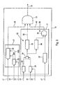
- FIG. 2 is the block diagram of a control system according to the invention.
- FIGS. 3 and 5 schematically illustrate parts of a system control according to the invention.
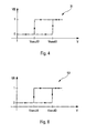
- Figures 4 and 6 are graphs to explain the operation of particular means of a control system according to the invention.
- control system 1 is applied to an aircraft 2, in particular a civil transport aircraft, as shown in FIG. considered in the following description by way of example.
- This transport plane 2 comprises a fuselage 3, to which are connected, among others, two wings 4 forming the main wing, a horizontal tailplane formed of two stabilizing planes 5 and a drift 6.
- Each of said stabilizer planes 5 is provided with a rudder depth 7, and the fin 6 is provided with a rudder 8.
- each of the wings 4 carries in particular, usually, fins 9, airbrakes 10 and several propulsion engines 11.
- each of said wings 4 is, in addition, provided with conventional high lift devices, know nozzles 12 to the leading edge of the wing 4 and flaps 13 to its trailing edge, which are likely to be brought into different positions. These high lift devices 12, 13 make it possible to increase the lift of said airplane 2.
- each wing of an aircraft of the type "Airbus A340" is equipped with seven spouts 12 and two shutters 13.
- the positions of the high lift devices 12, 13 progressively vary between a first position corresponding to a full retraction (or retraction) of said spouts and flaps ("cruising" position) and a second position corresponding to a complete exit (or deployment) of said spouts and flaps.
- the control system 1 is intended more particularly to automatically control said devices hypersustents to automatically optimize the position of these last with respect to unfavorable flight conditions in terms of loads aerodynamic. It is particularly well adapted (although not exclusively) to the control of said leading edge slats 12, as devices lift.
- the system 1 inhibits (via device 20) their output and protects and the aircraft 2 vis-à-vis such adverse situations, specified below.
- control of the nozzles 12 is performed automatically, without any intervention of the pilot of the aircraft 2, which allows audit pilot to focus exclusively on the strict aspects of pilotage.
- said device 19 monitors the effective speed V of the aircraft 2 to detect the presence of aerodynamic loads too significant, likely to damage said nozzles 12.
- This device 19 also monitors the actual incidence ⁇ of the airplane 2, in order to ensure, in the case of a configuration change of the nozzles 12, that said incidence ⁇ is not too close to (or even exceed) stall incidence of the new configuration (which one seeks to obtain).
- Said device 1 9 is connected by a plurality of links l1 to l7 (grouped together under a single reference L1 on! a) 2) to a set 27 sources of information specified below.
- Said means 21 of the device 19 comprises a comparator 28 for compare the effective speed V of the aircraft 2 (received by the link l1) to said authorized speed limit corresponding to a maximum authorized speed, received from a table 29 by a link 30A.
- This table 29 gives, according to the current configuration of spouts / flaps (connection l2) and the mass of the aircraft 2 (link l3), said speed maximum allowed Vseuil1 which represents the speed as the speed V of the airplane 2 must not exceed so as not to damage the nozzles 12. Beyond this speed Vseuil1, the beaks 12 are retracted, in order to protect against excessive aerodynamic loads.
- a hysteresis element 31 (FIG. 4) is introduced into the comparator 28. So, as long as the speed of the plane 2 did not go down below a speed Vseuil2 (lower than the speed Vseuil1 and transmitted by a link 30B to comparator 28), said comparator 28 as a binary value VB the value "1" at the AND logic gate 23, that is to say the beaks 12 are then not allowed to be redeployed. They stay therefore retracted.
- the previous condition is not enough to allow retraction 12.
- This means 22 comprises a table 33 which calculates, according to the configuration that is sought to obtain to protect the nozzles 12 (link l5) and according to the Mach number of the aircraft 2 (link l6), the incidence stall ⁇ s this configuration that we seek to obtain.
- a calculating means 34 then calculates the difference between this incidence of stalling ⁇ s and the effective incidence ⁇ , possibly smoothed, of the airplane 2. If the difference obtained is too small, it means that a retraction beaks 12 would bring the aircraft 2 in a condition close to that of stall. This difference must therefore be greater than a threshold ⁇ seuil1 representing a sufficient margin of safety to retract the beaks 12. A value of 5 ° for this threshold ⁇ seuil1 seems realistic.
- a comparator 35 performs the corresponding comparison.
- the derivative of the incidence ⁇ is furthermore monitored, which allows to verify its direction of evolution.
- the incidence ⁇ following a strong gust of vertical wind, for example, can strongly vary and exceed in the short term the incidence of stalling ⁇ s.
- the device 19 can have means 36 for monitoring the direction of variation of the incidence ⁇ . To do this, it is necessary that the derivative of the incidence (received by the link l7) is not too big (it must remain below a threshold ⁇ seuil2 predetermined, this is verified by a comparator 37) and that the incidence ⁇ is not too close to the incidence of stalling ⁇ s (the difference received means 34 between these incidences ⁇ s and ⁇ must be greater than one threshold ⁇ seuil3, that is what a comparator 38) verifies, in order to be certain that the change in incidence will not make it reach or exceed the incidence stalling ⁇ s.
- ⁇ seuil2 can vary from 0.5 ° / s to 1 ° / s and ⁇ seuil3 can worth about 7 °.
- the means 36 allows the retraction of the nozzles 1 2, thanks to an AND logic gate 39 which is connected by a link 40 to the door 23.
- Means 22 and 36 can be mounted in one and same unit 41.
- the two (or three) aforementioned states [relative to the speed (average 21) and the incidence (average 22) of the aircraft 2, as well as possibly the derivative incidence (average 36)] must therefore be combined, so that the device 19 can send to the actuating means 14 the retraction order spouts 12, via the AND gate 23, via the link 24.
- the device 20 takes into account the altitude conditions and speed of the aircraft 2, to prohibit the control means 18 to command an output of the nozzles 12, when flight situations may to be harmful to said nozzles 12 or to the behavior of the airplane 2 (second aforementioned flight condition) are encountered.
- said device 20 can act (in a simplified way) by a link 42 on a switching means 43 provided on the link 18B connecting the means of control 18 to the actuating means 14 ( Figure 2).
- the device 20 is connected by a plurality of links e1 to e7 (grouped together under a single reference E1 in FIG. 2), to the assembly 27 sources of information.
- Said means 45 comprises a comparator 50 for comparing the speed effective V of the aircraft 2 (received by the link e1) at said speed limit allowed corresponding to a maximum authorized speed of a table 51 by a link 52A.
- This table 51 which can be similar to the table 29 of FIG. 3, is also a function of the mass of plane 2 (link e3) but, this time, depending on the configuration of beaks / flaps that are to be reached (link e2).
- This table 51 gives the maximum speed Vseuil3 that the speed V of the aircraft 2 must not exceed so as not to damage the nozzles 12 when they leave. Beyond this speed Vseuil3, the exit of the beaks 12 is inhibited to protect them against aerodynamic loads excessive.
- a hysteresis element 53 (FIG. 6) is introduced into the comparator 50.
- said comparator 50 emits as a binary value VB the value "1" at the logic gate OR 47, that is to say the beaks 12 are then not allowed to be deployed. They stay therefore retracted.
- the value "0" is transmitted to the OR logic gate 47, as a binary value VB.
- the means 46 checks whether the output of said nozzles 12 is compatible with the flight altitude of the aircraft 2.
- said means 46 has a table 55 giving, depending on the configuration that we seeks to reach (link e5), the maximum possible altitude for this configuration. For example, an outlet of the nozzles 12 from their position "0" ("cruise" position) is only allowed if the flight altitude is lower than at 20,000 feet (about 6,000 meters). So, if the calculated difference by means 56 between the altitude of the aircraft 2 (received by the link e4) and the maximum altitude given by table 55 is positive (verification done by a comparator 57), it is forbidden to remove the nozzles 12.
- the exit ban of the beaks 12 is therefore linked to two conditions : a condition related to speed (and therefore to aerodynamic loads applying on said nozzles 12) and a condition related to the altitude of flight. If either of these conditions is encountered, the nozzles 12 are not allowed to be deployed, thanks to the OR 47 logic gate.
- the exit ban order nozzles 12 is activated. This is the function implemented by a logic gate ET 61 which is connected by links 62 and 63 respectively to said doors 47 and 59.
- said means 61 inhibits control commands corresponding to any actuation of the control member 16 to deploy said nozzles 12 when, at the same time, said means 54 detects such actuation and said means 47 generates inhibition orders.
- the order of command sent to the means actuation 14 is therefore a function of the flight conditions. If no contraindication to change the usual behavior is activated, the control means 18 reacts in the usual way to the orders given by the pilot via the control member 16, that is to say that the position of the nozzles 12 is then calculated by a standard table which is integrated in the control means 18. This table is a function of the position of the control member 16, determined by the pilot.
- the device 1 9 orders the retraction of the nozzles 12, the latter are retracted in a configuration giving them full security vis-à-vis aerodynamic loads and stall incidence.
- This configuration is determined by the device 19 according to the position of the controller 16, the incidence ⁇ and the number of Mach of the aircraft 2.
- the device 19 inhibits the signal ordering retraction 12.
- the spouts 12 are then again ordered from usual way by the control means 18.
- the present invention described above is applied, according to a preferred embodiment, at 12 edge nozzles wing attack 4 of an airplane 2.
- the present invention can be applied to other devices aircraft hypersustents, for example simultaneously with said nozzles 12 and flaps 13 of the aircraft 2.
Landscapes
- Engineering & Computer Science (AREA)
- Aviation & Aerospace Engineering (AREA)
- Radar, Positioning & Navigation (AREA)
- Remote Sensing (AREA)
- Physics & Mathematics (AREA)
- General Physics & Mathematics (AREA)
- Automation & Control Theory (AREA)
- Traffic Control Systems (AREA)
- Control Of Position, Course, Altitude, Or Attitude Of Moving Bodies (AREA)
- Heterocyclic Carbon Compounds Containing A Hetero Ring Having Oxygen Or Sulfur (AREA)
Abstract
Description
- détermination du domaine de vol minimal requis ;
- prise en compte de rafales de vent réglementaires pour en déduire les charges aérodynamiques maximales correspondantes ;
- application des autres charges possibles rencontrées par les dispositifs hypersustentateurs (charges au sol par exemple) pour en déduire les charges limites ; et
- détermination des charges extrêmes associées par application d'un coefficient de sécurité à partir desdites charges limites.
- le document FR-2 425 380 décrit un système de commande qui, lorsqu'un moteur de l'avion tombe en panne, agit automatiquement sur les gouvernes pour reconfigurer aérodynamiquement l'avion, de manière à compenser l'effet de la perte de poussée sur les caractéristiques aérodynamiques de l'aile ;
- le document US-4 042 197 décrit un dispositif qui a pour but d'optimiser, en phase de décollage et d'approche d'un avion, la position des volets, ainsi que la poussée de manière à réduire sensiblement le bruit engendré par ces équipements ; et
- le document FR-2 817 535 divulgue un système permettant d'optimiser automatiquement la position de dispositifs hypersustentateurs lors de la phase de décollage d'un aéronef afin de réduire la longueur de piste nécessaire au décollage et de réduire la traínée, ce qui permet d'obtenir une pente minimale de montée (avec un moteur en panne) permettant un décollage en toute sécurité.
- des moyens d'actionnement, pour déplacer lesdits dispositifs hypersustentateurs, en fonction d'ordres de commande reçus ;
- au moins un organe de commande susceptible d'être actionné par un pilote de l'aéronef ; et
- une unité de commande qui comporte un moyen de commande qui est susceptible d'engendrer des ordres de commande, en fonction de l'actionnement dudit organe de commande, pour commander lesdits moyens d'actionnement de sorte que ces derniers amènent lesdits dispositifs hypersustentateurs dans une position déterminée,
- un premier dispositif susceptible d'engendrer, automatiquement, des ordres de commande auxiliaires qui sont transmis auxdits moyens d'actionnement pour rétracter automatiquement lesdits dispositifs hypersustentateurs, lorsque l'aéronef se trouve dans une première condition de vol ; et
- un second dispositif pour inhiber, automatiquement, des ordres de commande engendrés par ledit moyen de commande suite à un actionnement dudit organe de commande pour déployer lesdits dispositifs hypersustentateurs, lorsque l'aéronef se trouve dans une seconde condition de vol.
- un premier moyen pour surveiller la vitesse de l'aéronef et émettre le cas échéant un premier signal indiquant un dépassement d'une vitesse limite autorisée;
- un deuxième moyen pour surveiller l'incidence de l'aéronef et émettre le cas échéant un deuxième signal indiquant un dépassement d'une incidence limite autorisée ; et
- un troisième moyen pour engendrer lesdits ordres de commande auxiliaires, lorsqu'au moins lesdits premier et deuxième moyens émettent en même temps lesdits premier et deuxième signaux.
- ledit premier moyen compare la vitesse effective de l'aéronef à ladite vitesse limite autorisée correspondant à une vitesse maximale autorisée, qui dépend de la configuration actuelle et de la masse de l'aéronef; et/ou
- ledit deuxième moyen compare l'incidence effective de l'aéronef à ladite incidence limite autorisée correspondant à une incidence de décrochage qui dépend d'une configuration de l'aéronef que l'on cherche à obtenir et du nombre de Mach de l'aéronef.
- un premier élément pour comparer la dérivée de l'incidence de l'aéronef à une valeur de seuil prédéterminée et émettre le cas échéant un signal indiquant un dépassement de cette valeur de seuil ;
- un deuxième élément pour comparer l'incidence effective de l'aéronef à une valeur d'incidence dépendant de l'incidence de décrochage et émettre le cas échéant un signal indiquant un dépassement de cette valeur d'incidence ; et
- un troisième élément pour engendrer ledit quatrième signal, lorsque lesdits premier et deuxième éléments émettent en même temps des signaux de dépassement.
- un cinquième moyen pour surveiller la vitesse de l'aéronef et émettre le cas échéant un cinquième signal indiquant un dépassement d'une vitesse limite autorisée;
- un sixième moyen pour surveiller l'altitude de l'aéronef et émettre le cas échéant un sixième signal indiquant un dépassement d'une altitude limite autorisée ; et
- un septième moyen pour engendrer des ordres d'inhibition, lorsqu'au moins l'un desdits cinquième et sixième moyens émet l'un desdits cinquième et sixième signaux.
- ledit cinquième moyen compare la vitesse effective de l'aéronef à ladite vitesse limite autorisée correspondant à une vitesse maximale autorisée, qui dépend de la configuration actuelle et de la masse de l'aéronef. De préférence, ledit cinquième moyen comporte, de plus, une boucle d'hystérésis, pour éviter de trop nombreux mouvements des dispositifs hypersustentateurs, dans le cas où la vitesse effective de l'aéronef oscille autour de ladite vitesse maximale autorisée ; et/ou
- ledit sixième moyen compare l'altitude effective de l'aéronef à ladite altitude limite autorisée correspondant à une altitude maximale possible pour une configuration de l'aéronef que l'on cherche à obtenir.
- un huitième moyen susceptible de détecter tout actionnement de l'organe de commande pour déployer lesdits dispositifs hypersustentateurs ; et
- un neuvième moyen qui inhibe les ordres de commande correspondant à un tel actionnement pour déployer lesdits dispositifs hypersustentateurs, lorsque, à la fois, ledit huitième moyen détecte un tel actionnement et ledit septième moyen engendre des ordres d'inhibition.
| Configuration de l'avion | Position des becs 12 | Position des volets 13 |
| "0" : non hypersustentée | 0 | 0 |
| "1 " : très faiblement hypersustentée | 20 | 0 |
| "1 +F" : faiblement hypersustentée | 20 | 17 |
| "2" : moyennement hypersustentée | 23 | 22 |
| "3" : très hypersustentée | 23 | 29 |
| "Full" : complètement hypersustentée | 23 | 34 |
- une pluralité de moyens d'actionnement (regroupés sous la référence unique 14 sur la figure 2), pour déplacer lesdits dispositifs hypersustentateurs 12, 13 (regroupés sous une référence 12, 13 sur la figure 2), en fonction d'ordres de commande reçus, comme illustré par une liaison 15 en traits mixtes;
- au moins un organe de commande 16, par exemple un levier becs/volets, qui est susceptible d'être actionné par un pilote de l'avion 2 ; et
- une unité de commande 17 qui comporte un moyen de commande 18 usuel, qui est susceptible d'engendrer des ordres de commande, en fonction de l'actionnement dudit organe de commande 16, reçu par une liaison 18A, pour commander lesdits moyens d'actionnement 14 (liaison 18B) de sorte que ces derniers amènent lesdits dispositifs hypersustentateurs 12, 13 dans une position déterminée.
- un dispositif 19 susceptible d'engendrer, automatiquement, des ordres de commande auxiliaires qui sont transmis auxdits moyens d'actionnement 14 pour rétracter automatiquement lesdits becs 12, lorsque l'avion 2 se trouve dans une première condition de vol précisée ci-dessous ; et
- un dispositif 20 pour inhiber, automatiquement, des ordres de commande engendrés par ledit moyen de commande 18 suite à un actionnement dudit organe de commande 16 pour déployer lesdits becs 12, lorsque l'avion 2 se trouve dans une seconde condition de vol précisée ci-dessous.
- un moyen 21 précisé ci-dessous, pour surveiller la vitesse V de l'avion 2 et émettre le cas échéant un premier signal indiquant un dépassement d'une vitesse limite autorisée ;
- un moyen 22 précisé ci-dessous, pour surveiller l'incidence α de l'avion 2 et émettre le cas échéant un deuxième signal indiquant un dépassement d'une incidence limite autorisée ; et
- un moyen 23, en l'occurrence une porte logique ET, pour engendrer lesdits ordres de commande auxiliaires (destinés à rétracter automatiquement lesdits becs 12) et les transmettre auxdits moyens d'actionnement 14 par l'intermédiaire d'une liaison 24, lorsqu'au moins lesdits moyens 21 et 22 émettent en même temps lesdits premier et deuxième signaux (liaisons 25 et 26).
- un moyen 45 pour surveiller la vitesse de l'avion 2 et émettre le cas échéant un premier signal indiquant un dépassement d'une vitesse limite autorisée ;
- un moyen 46 pour surveiller l'altitude de l'avion 2 et émettre le cas échéant un second signal indiquant un dépassement d'une altitude limite autorisée ; et
- un moyen 47, en l'occurrence une porte logique OU, pour engendrer des ordres d'inhibition, lorsqu'au moins l'un desdits moyens 45 et 46 émet l'un desdits premier et second signaux (par des liaisons 48 et 49).
Claims (13)
- Système pour commander automatiquement des dispositifs hypersustentateurs (12, 13) d'un aéronef (2), en particulier des becs (12) de bord d'attaque d'aile (4), qui sont susceptibles d'être déployés et rétractés, ledit système (1) comportant :caractérisé en ce que ladite unité de commande (17) comporte de plus:des moyens d'actionnement (14), pour déplacer lesdits dispositifs hypersustentateurs (12, 13), en fonction d'ordres de commande reçus ;au moins un organe de commande (16) susceptible d'être actionné par un pilote de l'aéronef (2) ; etune unité de commande (17) qui comporte un moyen de commande (18) qui est susceptible d'engendrer des ordres de commande, en fonction de l'actionnement dudit organe de commande (16), pour commander lesdits moyens d'actionnement (14) de sorte que ces derniers amènent lesdits dispositifs hypersustentateurs (12, 13) dans une position déterminée,un premier dispositif (19) susceptible d'engendrer, automatiquement, des ordres de commande auxiliaires qui sont transmis auxdits moyens d'actionnement (14) pour rétracter automatiquement lesdits dispositifs hypersustentateurs (12, 13), lorsque l'aéronef (2) se trouve dans une première condition de vol ; etun second dispositif (20) pour inhiber, automatiquement, des ordres de commande engendrés par ledit moyen de commande (18) suite à un actionnement dudit organe de commande (16) pour déployer lesdits dispositifs hypersustentateurs (12, 13), lorsque l'aéronef (2) se trouve dans une seconde condition de vol.
- Système selon la revendication 1,
caractérisé en ce que ledit premier dispositif (19) vérifie en continu, de façon automatique, si l'aéronef (2) se trouve dans ladite première condition de vol, en tenant compte de la vitesse et de l'incidence de l'aéronef (2). - Système selon l'une des revendications 1 et 2,
caractérisé en ce que ledit premier dispositif (19) comporte:un premier moyen (21) pour surveiller la vitesse de l'aéronef (2) et émettre le cas échéant un premier signal indiquant un dépassement d'une vitesse limite autorisée ;un deuxième moyen (22) pour surveiller l'incidence de l'aéronef (2) et émettre le cas échéant un deuxième signal indiquant un dépassement d'une incidence limite autorisée ; etun troisième moyen (23) pour engendrer lesdits ordres de commande auxiliaires, lorsqu'au moins lesdits premier et deuxième moyens (21, 22) émettent en même temps lesdits premier et deuxième signaux. - Système selon la revendication 3,
caractérisé en ce que ledit premier moyen (21) compare la vitesse effective de l'aéronef (2) à ladite vitesse limite autorisée correspondant à une vitesse maximale autorisée, qui dépend de la configuration actuelle et de la masse de l'aéronef (2). - Système selon l'une des revendications 3 et 4,
caractérisé en ce que ledit deuxième moyen (22) compare l'incidence effective de l'aéronef (2) à ladite incidence limite autorisée correspondant à une incidence de décrochage qui dépend d'une configuration de l'aéronef (2) que l'on cherche à obtenir et du nombre de Mach de l'aéronef (2). - Système selon l'une quelconque des revendications 3 à 5,
caractérisé en ce que ledit premier dispositif (19) comporte, de plus, un quatrième moyen (36) pour surveiller la dérivée de l'incidence de l'aéronef (2) et émettre le cas échéant un quatrième signal, et en ce que ledit troisième moyen (3) engendre lesdits ordres de commande auxiliaires, uniquement lorsque ledit quatrième signal est émis en même temps que lesdits premier et deuxième signaux. - Système selon la revendication 6,
caractérisé en ce que ledit quatrième moyen (36) comporte:un premier élément (37) pour comparer la dérivée de l'incidence de l'aéronef (2) à une valeur de seuil prédéterminée et émettre le cas échéant un signal indiquant un dépassement de cette valeur de seuil;un deuxième élément (38) pour comparer l'incidence effective de l'aéronef (2) à une valeur d'incidence dépendant de l'incidence de décrochage et émettre le cas échéant un signal indiquant un dépassement de cette valeur d'incidence ; etun troisième élément (39) pour engendrer ledit quatrième signal, lorsque lesdits premier et deuxième éléments (37, 38) émettent en même temps des signaux de dépassement. - Système selon l'une quelconque des revendications précédentes,
caractérisé en ce que ledit second dispositif (20) vérifie, de façon automatique, si l'aéronef (2) se trouve dans ladite seconde condition de vol, en tenant compte de la vitesse et de l'altitude de l'aéronef (2). - Système selon l'une quelconque des revendications précédentes,
caractérisé en ce que ledit second dispositif (20) comporte:un cinquième moyen (45) pour surveiller la vitesse de l'aéronef (2) et émettre le cas échéant un cinquième signal indiquant un dépassement d'une vitesse limite autorisée;un sixième moyen (46) pour surveiller l'altitude de l'aéronef (2) et émettre le cas échéant un sixième signal indiquant un dépassement d'une altitude limite autorisée ; etun septième moyen (47) pour engendrer des ordres d'inhibition, lorsqu'au moins l'un desdits cinquième et sixième moyens (45, 46) émet l'un desdits cinquième et sixième signaux. - Système selon la revendication 9,
caractérisé en ce que ledit cinquième moyen (45) compare la vitesse effective de l'aéronef (2) à ladite vitesse limite autorisée correspondant à une vitesse maximale autorisée, qui dépend de la configuration actuelle et de la masse de l'aéronef (2). - Système selon la revendication 10,
caractérisé en ce que ledit cinquième moyen (45) comporte, de plus, une boucle d'hystérésis (53). - Système selon l'une quelconque des revendications 9 à 11,
caractérisé en ce que ledit sixième moyen (46) compare l'altitude effective de l'aéronef (2) à ladite altitude limite autorisée correspondant à une altitude maximale possible pour une configuration de l'aéronef (2) que l'on cherche à obtenir. - Système selon l'une quelconque des revendications 9 à 12,
caractérisé en ce que ledit second dispositif (20) comporte, de plus :un huitième moyen (54) susceptible de détecter tout actionnement de l'organe de commande (16) pour déployer lesdits dispositifs hypersustentateurs (12, 13) ; etun neuvième moyen (61) qui inhibe les ordres de commande correspondant à un tel actionnement pour déployer lesdits dispositifs hypersustentateurs (12, 13), lorsque, à la fois, ledit huitième moyen (54) détecte un tel actionnement et ledit septième moyen (47) engendre des ordres d'inhibition.
Applications Claiming Priority (2)
| Application Number | Priority Date | Filing Date | Title |
|---|---|---|---|
| FR0308603 | 2003-07-15 | ||
| FR0308603A FR2857760B1 (fr) | 2003-07-15 | 2003-07-15 | Systeme pour commander automatiquement des dispositifs hypersustentateurs d'un aeronef, en particulier des becs de bord d'attaque d'aile. |
Publications (2)
| Publication Number | Publication Date |
|---|---|
| EP1498794A1 true EP1498794A1 (fr) | 2005-01-19 |
| EP1498794B1 EP1498794B1 (fr) | 2006-05-31 |
Family
ID=33462524
Family Applications (1)
| Application Number | Title | Priority Date | Filing Date |
|---|---|---|---|
| EP04291522A Expired - Lifetime EP1498794B1 (fr) | 2003-07-15 | 2004-06-17 | Système pour commander automatiquement des dispositifs hypersustentateurs d'un aéronef, en particulier des becs de bord d'attaque d'aile |
Country Status (7)
| Country | Link |
|---|---|
| US (1) | US7366592B2 (fr) |
| EP (1) | EP1498794B1 (fr) |
| AT (1) | ATE328309T1 (fr) |
| CA (1) | CA2472291C (fr) |
| DE (1) | DE602004001023T2 (fr) |
| ES (1) | ES2265624T3 (fr) |
| FR (1) | FR2857760B1 (fr) |
Cited By (6)
| Publication number | Priority date | Publication date | Assignee | Title |
|---|---|---|---|---|
| FR2902078A1 (fr) * | 2006-06-13 | 2007-12-14 | Airbus France Sas | Procede de pilotage d'un aeronef en phase d'approche |
| WO2009040102A1 (fr) * | 2007-09-24 | 2009-04-02 | Airbus Deutschland Gmbh | Commande automatique du système d'hypersustentation d'un avion |
| JP2010509118A (ja) * | 2006-11-11 | 2010-03-25 | エアバス・オペレーションズ・ゲーエムベーハー | 航空機翼の高揚力システム及びその操作方法 |
| WO2011154249A1 (fr) * | 2010-06-11 | 2011-12-15 | Thales | Procédé et dispositif pour la protection d'un aéronef |
| CN102458983A (zh) * | 2009-04-16 | 2012-05-16 | 空中客车营运有限公司 | 用于飞行器的增升系统、飞行器系统以及具有增升系统的螺旋桨飞行器 |
| CN104443357B (zh) * | 2013-09-24 | 2018-08-31 | 波音公司 | 用于前缘和后缘装置的控制接口 |
Families Citing this family (16)
| Publication number | Priority date | Publication date | Assignee | Title |
|---|---|---|---|---|
| US7556224B2 (en) * | 2005-12-27 | 2009-07-07 | Honeywell International Inc. | Distributed flight control surface actuation system |
| US9671788B2 (en) * | 2007-11-27 | 2017-06-06 | The Boeing Company | Vertical path control augmentation using lateral control surfaces |
| FR2939528B1 (fr) * | 2008-12-08 | 2011-02-11 | Airbus France | Dispositif et procede de generation automatique d'un ordre de commande d'une gouverne d'aeronef |
| FR2942611B1 (fr) * | 2009-03-02 | 2012-09-28 | Airbus France | Procede et dispositif d'optimisation automatique en vol de la configuration aerodynamique d'un avion |
| FR2947242B1 (fr) * | 2009-06-24 | 2013-02-22 | Airbus | Procede et dispositif d'equilibrage lateral en vol d'un avion |
| EP2604515B1 (fr) * | 2011-12-12 | 2017-11-08 | Airbus Operations GmbH | Procédé et système de contrôle d'un dispositif de portance élevée ou d'une surface de commande de vol, et avion ou engin spatial comprenant un tel système |
| DE102012001268A1 (de) | 2012-01-23 | 2013-07-25 | Airbus Operations Gmbh | Verfahren zur Planung eines Landeanflugs eines Flugzeugs, Computerprogrammprodukt, Medium mit einem darauf gespeicherten Landeanflugplan sowie Vorrichtung zur Planung eines Landeanflugs |
| US20160009364A1 (en) * | 2013-02-23 | 2016-01-14 | Vires Aeronautics, Inc. | Fluid Boundary Layer Control |
| US9254909B2 (en) * | 2013-09-24 | 2016-02-09 | The Boeing Company | Optimized flap positioning for go-around operations |
| US9359065B2 (en) * | 2013-09-24 | 2016-06-07 | The Boeing Company | System and method for optimizing performance of an aircraft |
| EP2913733A1 (fr) * | 2014-02-27 | 2015-09-02 | Airbus Operations GmbH | Système de commande des dispositifs hypersustentateurs d'un aéronef et procédé pour commander la configuration de tels dispositifs |
| CN105116271B (zh) * | 2015-08-07 | 2019-04-26 | 深圳一电航空技术有限公司 | 桨叶检测装置及方法、桨叶组件、飞行器及其控制方法 |
| FR3052251B1 (fr) * | 2016-06-03 | 2018-05-18 | Airbus Operations (S.A.S.) | Procede d'optimisation des parametres de decollage d'un aeronef |
| US10671090B2 (en) | 2017-09-01 | 2020-06-02 | Embraer S.A. | Automatic command for lift control devices |
| FR3101968B1 (fr) * | 2019-10-14 | 2021-10-08 | Airbus Operations Sas | Système et procédé de commande d’un actionneur d’une gouverne d’un aéronef. |
| GB2622800B (en) | 2022-09-27 | 2025-07-16 | Airbus Operations Ltd | Flight control surface |
Citations (5)
| Publication number | Priority date | Publication date | Assignee | Title |
|---|---|---|---|---|
| US4017045A (en) * | 1975-12-24 | 1977-04-12 | The Bendix Corporation | Flap compensation system for use when controlling the pitch attitude of an aircraft |
| US4042197A (en) * | 1975-09-29 | 1977-08-16 | The Boeing Company | Automatic controls for airplane take-off and landing modes |
| FR2425380A1 (fr) * | 1978-05-11 | 1979-12-07 | Boeing Co | Installation de commande automatique pour avion a decollage et atterrissage courts (adac) |
| US4591113A (en) * | 1983-05-26 | 1986-05-27 | The Secretary Of State For Defence In Her Britannic Majesty's Government Of The United Kingdom Of Great Britain And Northern Ireland | Aircraft controls |
| FR2817535A1 (fr) * | 2000-12-06 | 2002-06-07 | Eads Airbus Sa | Systeme pour commander automatiquement des dispositifs hypersustentateurs d'un aeronef durant le decollage |
Family Cites Families (4)
| Publication number | Priority date | Publication date | Assignee | Title |
|---|---|---|---|---|
| US99479A (en) * | 1870-02-01 | Edwin r | ||
| US20020047072A1 (en) * | 1997-02-13 | 2002-04-25 | Theodore Garver | Lift multiplying device for aircraft |
| US5921506A (en) * | 1997-09-25 | 1999-07-13 | Northrop Grumman Corporation | Extendible leading edge flap |
| US6824109B2 (en) * | 2002-10-30 | 2004-11-30 | E-Win Corporation | Lift adjusting device for aircraft |
-
2003
- 2003-07-15 FR FR0308603A patent/FR2857760B1/fr not_active Expired - Fee Related
-
2004
- 2004-06-17 ES ES04291522T patent/ES2265624T3/es not_active Expired - Lifetime
- 2004-06-17 DE DE602004001023T patent/DE602004001023T2/de not_active Expired - Lifetime
- 2004-06-17 EP EP04291522A patent/EP1498794B1/fr not_active Expired - Lifetime
- 2004-06-17 AT AT04291522T patent/ATE328309T1/de not_active IP Right Cessation
- 2004-06-21 CA CA2472291A patent/CA2472291C/fr not_active Expired - Fee Related
- 2004-07-14 US US10/890,182 patent/US7366592B2/en active Active
Patent Citations (5)
| Publication number | Priority date | Publication date | Assignee | Title |
|---|---|---|---|---|
| US4042197A (en) * | 1975-09-29 | 1977-08-16 | The Boeing Company | Automatic controls for airplane take-off and landing modes |
| US4017045A (en) * | 1975-12-24 | 1977-04-12 | The Bendix Corporation | Flap compensation system for use when controlling the pitch attitude of an aircraft |
| FR2425380A1 (fr) * | 1978-05-11 | 1979-12-07 | Boeing Co | Installation de commande automatique pour avion a decollage et atterrissage courts (adac) |
| US4591113A (en) * | 1983-05-26 | 1986-05-27 | The Secretary Of State For Defence In Her Britannic Majesty's Government Of The United Kingdom Of Great Britain And Northern Ireland | Aircraft controls |
| FR2817535A1 (fr) * | 2000-12-06 | 2002-06-07 | Eads Airbus Sa | Systeme pour commander automatiquement des dispositifs hypersustentateurs d'un aeronef durant le decollage |
Cited By (17)
| Publication number | Priority date | Publication date | Assignee | Title |
|---|---|---|---|---|
| WO2007144485A1 (fr) * | 2006-06-13 | 2007-12-21 | Airbus France | Procede de pilotage d'un aeronef en phase d'approche |
| JP2009539693A (ja) * | 2006-06-13 | 2009-11-19 | エアバス フランス | 進入段階での航空機の操縦方法 |
| RU2389647C1 (ru) * | 2006-06-13 | 2010-05-20 | Эрбюс Франс | Способ пилотирования летательного аппарата в фазе захода на посадку |
| US9457888B2 (en) | 2006-06-13 | 2016-10-04 | Airbus Operations Sas | Method for piloting an aircraft in approach phase |
| FR2902078A1 (fr) * | 2006-06-13 | 2007-12-14 | Airbus France Sas | Procede de pilotage d'un aeronef en phase d'approche |
| JP2010509118A (ja) * | 2006-11-11 | 2010-03-25 | エアバス・オペレーションズ・ゲーエムベーハー | 航空機翼の高揚力システム及びその操作方法 |
| US8382044B2 (en) | 2006-11-11 | 2013-02-26 | Airbus Operations Gmbh | High-lift system on the wing of an aircraft, and method for its operation |
| CN101808896B (zh) * | 2007-09-24 | 2013-01-30 | 空中客车营运有限公司 | 飞机的高升力系统的自动控制装置 |
| WO2009040102A1 (fr) * | 2007-09-24 | 2009-04-02 | Airbus Deutschland Gmbh | Commande automatique du système d'hypersustentation d'un avion |
| US8356776B2 (en) | 2007-09-24 | 2013-01-22 | Airbus Operations Gmbh | Automatic control of a high lift system of an aircraft |
| CN102458983A (zh) * | 2009-04-16 | 2012-05-16 | 空中客车营运有限公司 | 用于飞行器的增升系统、飞行器系统以及具有增升系统的螺旋桨飞行器 |
| CN102458983B (zh) * | 2009-04-16 | 2015-10-21 | 空中客车营运有限公司 | 用于飞行器的增升系统、飞行器系统以及具有增升系统的螺旋桨飞行器 |
| FR2961178A1 (fr) * | 2010-06-11 | 2011-12-16 | Thales Sa | Procede et dispositif pour la protection d'un aeronef |
| US8965603B2 (en) | 2010-06-11 | 2015-02-24 | Thales | Method and device for protecting an aircraft |
| RU2587324C2 (ru) * | 2010-06-11 | 2016-06-20 | Таль | Способ и устройство для защиты летательного аппарата |
| WO2011154249A1 (fr) * | 2010-06-11 | 2011-12-15 | Thales | Procédé et dispositif pour la protection d'un aéronef |
| CN104443357B (zh) * | 2013-09-24 | 2018-08-31 | 波音公司 | 用于前缘和后缘装置的控制接口 |
Also Published As
| Publication number | Publication date |
|---|---|
| ATE328309T1 (de) | 2006-06-15 |
| US20070185628A1 (en) | 2007-08-09 |
| DE602004001023D1 (de) | 2006-07-06 |
| DE602004001023T2 (de) | 2007-01-04 |
| EP1498794B1 (fr) | 2006-05-31 |
| FR2857760B1 (fr) | 2005-09-23 |
| US7366592B2 (en) | 2008-04-29 |
| FR2857760A1 (fr) | 2005-01-21 |
| ES2265624T3 (es) | 2007-02-16 |
| CA2472291A1 (fr) | 2005-01-15 |
| CA2472291C (fr) | 2010-12-21 |
Similar Documents
| Publication | Publication Date | Title |
|---|---|---|
| EP1498794B1 (fr) | Système pour commander automatiquement des dispositifs hypersustentateurs d'un aéronef, en particulier des becs de bord d'attaque d'aile | |
| EP1223491B1 (fr) | Système pour commander automatiquement des dispositifs hypersustentateurs d'un aéronef durant le décollage | |
| EP3091412B1 (fr) | Système de commande de giravion, giravion associé et méthode de commande correspondante | |
| CA2640925C (fr) | Procede et dispositif de commande de la poussee d'un aeronef multimoteur | |
| EP3002209B1 (fr) | Giravion muni d'un dispositif stabilisateur | |
| EP1568605B1 (fr) | Procédé et dispositif pour l'optimisation du braquage des volets déporteurs d'un aéronef en vol | |
| EP0584010B1 (fr) | Procédé de commande des gouvernes d'un avion pour compenser à basse vitesse une déviation latérale de trajectoire | |
| EP3112971B1 (fr) | Procédé de détermination de valeurs de consigne de la vitesse air longitudinale et de la vitesse sol longitudinale d'un aéronef à voilure tournante selon son exposition au vent | |
| EP1607816B1 (fr) | Système d'aide au pilotage d'un aéronef lors de l'approche d'une piste d'atterissage en vue d'un atterissage | |
| CA2622110C (fr) | Procede et dispositif pour attenuer sur un aeronef les effets d'une turbulence verticale | |
| EP1768899B1 (fr) | Procede et dispositif d'amelioration de la manoeuvrabilite d'un aeronef lors des phases d'approche avant l'atterrissage puis d'arrondi | |
| EP1591854B1 (fr) | Procédé d'aide au décollage d'un aéronef | |
| FR2946021A1 (fr) | Procede et dispositif pour la detection d'une dissymetrie de poussee d'un aeronef lors d'un atterrissage | |
| CN105283383A (zh) | 飞机地面升力卸减飞行控制功能 | |
| EP1026565B1 (fr) | Système pour la commande en lacet d'un aéronef | |
| WO2007096507A1 (fr) | Systeme de commande electrique pour une gouverne de direction d'un avion | |
| FR2929724A1 (fr) | Procede pour la determination de la vitesse de sortie d'effet de sol d'un aeronef. | |
| WO2021239696A1 (fr) | Procédé et système d'aide à l'approche d'un aéronef en vue de l'atterrissage | |
| FR2950165A1 (fr) | Procede et systeme pour l'amelioration des performances d'un aeronef au decollage | |
| EP3882141B1 (fr) | Procédé et système de réduction du bruit en vol d'un hélicoptère hybride par gestion de l'incidence de son rotor principal et de la poussée de chaque hélice | |
| EP3251945B1 (fr) | Procede d'optimisation des parametres de decollage d'un aeronef | |
| CA2472316C (fr) | Procede et dispositif pour controler l'assiette d'un avion | |
| FR2900126A1 (fr) | Procede et dispositif pour la reduction des tourbillons de sillage d'un aeronef en phase d'approche/atterrissage | |
| FR2873094A1 (fr) | Procede et dispositif d'amelioration de la manoeuvrabilite d'un aeronef lors des phases d'approche avant l'atterrissage puis d'arrondi | |
| FR2929241A1 (fr) | Procede et dispositif de reduction du tremblement d'un avion. |
Legal Events
| Date | Code | Title | Description |
|---|---|---|---|
| PUAI | Public reference made under article 153(3) epc to a published international application that has entered the european phase |
Free format text: ORIGINAL CODE: 0009012 |
|
| AK | Designated contracting states |
Kind code of ref document: A1 Designated state(s): AT BE BG CH CY CZ DE DK EE ES FI FR GB GR HU IE IT LI LU MC NL PL PT RO SE SI SK TR |
|
| AX | Request for extension of the european patent |
Extension state: AL HR LT LV MK |
|
| 17P | Request for examination filed |
Effective date: 20050211 |
|
| AKX | Designation fees paid |
Designated state(s): AT BE BG CH CY CZ DE DK EE ES FI FR GB GR HU IE IT LI LU MC NL PL PT RO SE SI SK TR |
|
| GRAP | Despatch of communication of intention to grant a patent |
Free format text: ORIGINAL CODE: EPIDOSNIGR1 |
|
| GRAS | Grant fee paid |
Free format text: ORIGINAL CODE: EPIDOSNIGR3 |
|
| GRAA | (expected) grant |
Free format text: ORIGINAL CODE: 0009210 |
|
| AK | Designated contracting states |
Kind code of ref document: B1 Designated state(s): AT BE BG CH CY CZ DE DK EE ES FI FR GB GR HU IE IT LI LU MC NL PL PT RO SE SI SK TR |
|
| PG25 | Lapsed in a contracting state [announced via postgrant information from national office to epo] |
Ref country code: SI Free format text: LAPSE BECAUSE OF FAILURE TO SUBMIT A TRANSLATION OF THE DESCRIPTION OR TO PAY THE FEE WITHIN THE PRESCRIBED TIME-LIMIT Effective date: 20060531 Ref country code: PL Free format text: LAPSE BECAUSE OF FAILURE TO SUBMIT A TRANSLATION OF THE DESCRIPTION OR TO PAY THE FEE WITHIN THE PRESCRIBED TIME-LIMIT Effective date: 20060531 Ref country code: SK Free format text: LAPSE BECAUSE OF FAILURE TO SUBMIT A TRANSLATION OF THE DESCRIPTION OR TO PAY THE FEE WITHIN THE PRESCRIBED TIME-LIMIT Effective date: 20060531 Ref country code: RO Free format text: LAPSE BECAUSE OF FAILURE TO SUBMIT A TRANSLATION OF THE DESCRIPTION OR TO PAY THE FEE WITHIN THE PRESCRIBED TIME-LIMIT Effective date: 20060531 Ref country code: IE Free format text: LAPSE BECAUSE OF FAILURE TO SUBMIT A TRANSLATION OF THE DESCRIPTION OR TO PAY THE FEE WITHIN THE PRESCRIBED TIME-LIMIT Effective date: 20060531 Ref country code: NL Free format text: LAPSE BECAUSE OF FAILURE TO SUBMIT A TRANSLATION OF THE DESCRIPTION OR TO PAY THE FEE WITHIN THE PRESCRIBED TIME-LIMIT Effective date: 20060531 Ref country code: AT Free format text: LAPSE BECAUSE OF FAILURE TO SUBMIT A TRANSLATION OF THE DESCRIPTION OR TO PAY THE FEE WITHIN THE PRESCRIBED TIME-LIMIT Effective date: 20060531 Ref country code: FI Free format text: LAPSE BECAUSE OF FAILURE TO SUBMIT A TRANSLATION OF THE DESCRIPTION OR TO PAY THE FEE WITHIN THE PRESCRIBED TIME-LIMIT Effective date: 20060531 Ref country code: CZ Free format text: LAPSE BECAUSE OF FAILURE TO SUBMIT A TRANSLATION OF THE DESCRIPTION OR TO PAY THE FEE WITHIN THE PRESCRIBED TIME-LIMIT Effective date: 20060531 |
|
| REG | Reference to a national code |
Ref country code: CH Ref legal event code: EP Ref country code: GB Ref legal event code: FG4D Free format text: NOT ENGLISH |
|
| GBT | Gb: translation of ep patent filed (gb section 77(6)(a)/1977) |
Effective date: 20060531 |
|
| REG | Reference to a national code |
Ref country code: IE Ref legal event code: FG4D Free format text: LANGUAGE OF EP DOCUMENT: FRENCH |
|
| PG25 | Lapsed in a contracting state [announced via postgrant information from national office to epo] |
Ref country code: MC Free format text: LAPSE BECAUSE OF NON-PAYMENT OF DUE FEES Effective date: 20060630 Ref country code: BE Free format text: LAPSE BECAUSE OF NON-PAYMENT OF DUE FEES Effective date: 20060630 |
|
| REF | Corresponds to: |
Ref document number: 602004001023 Country of ref document: DE Date of ref document: 20060706 Kind code of ref document: P |
|
| PG25 | Lapsed in a contracting state [announced via postgrant information from national office to epo] |
Ref country code: DK Free format text: LAPSE BECAUSE OF FAILURE TO SUBMIT A TRANSLATION OF THE DESCRIPTION OR TO PAY THE FEE WITHIN THE PRESCRIBED TIME-LIMIT Effective date: 20060831 |
|
| REG | Reference to a national code |
Ref country code: SE Ref legal event code: TRGR |
|
| PG25 | Lapsed in a contracting state [announced via postgrant information from national office to epo] |
Ref country code: PT Free format text: LAPSE BECAUSE OF FAILURE TO SUBMIT A TRANSLATION OF THE DESCRIPTION OR TO PAY THE FEE WITHIN THE PRESCRIBED TIME-LIMIT Effective date: 20061031 |
|
| NLV1 | Nl: lapsed or annulled due to failure to fulfill the requirements of art. 29p and 29m of the patents act | ||
| REG | Reference to a national code |
Ref country code: IE Ref legal event code: FD4D |
|
| REG | Reference to a national code |
Ref country code: ES Ref legal event code: FG2A Ref document number: 2265624 Country of ref document: ES Kind code of ref document: T3 |
|
| PLBE | No opposition filed within time limit |
Free format text: ORIGINAL CODE: 0009261 |
|
| STAA | Information on the status of an ep patent application or granted ep patent |
Free format text: STATUS: NO OPPOSITION FILED WITHIN TIME LIMIT |
|
| 26N | No opposition filed |
Effective date: 20070301 |
|
| BERE | Be: lapsed |
Owner name: AIRBUS FRANCE Effective date: 20060630 |
|
| PG25 | Lapsed in a contracting state [announced via postgrant information from national office to epo] |
Ref country code: GR Free format text: LAPSE BECAUSE OF FAILURE TO SUBMIT A TRANSLATION OF THE DESCRIPTION OR TO PAY THE FEE WITHIN THE PRESCRIBED TIME-LIMIT Effective date: 20060901 |
|
| PG25 | Lapsed in a contracting state [announced via postgrant information from national office to epo] |
Ref country code: EE Free format text: LAPSE BECAUSE OF FAILURE TO SUBMIT A TRANSLATION OF THE DESCRIPTION OR TO PAY THE FEE WITHIN THE PRESCRIBED TIME-LIMIT Effective date: 20060531 Ref country code: BG Free format text: LAPSE BECAUSE OF FAILURE TO SUBMIT A TRANSLATION OF THE DESCRIPTION OR TO PAY THE FEE WITHIN THE PRESCRIBED TIME-LIMIT Effective date: 20060831 |
|
| PG25 | Lapsed in a contracting state [announced via postgrant information from national office to epo] |
Ref country code: TR Free format text: LAPSE BECAUSE OF FAILURE TO SUBMIT A TRANSLATION OF THE DESCRIPTION OR TO PAY THE FEE WITHIN THE PRESCRIBED TIME-LIMIT Effective date: 20060531 Ref country code: HU Free format text: LAPSE BECAUSE OF FAILURE TO SUBMIT A TRANSLATION OF THE DESCRIPTION OR TO PAY THE FEE WITHIN THE PRESCRIBED TIME-LIMIT Effective date: 20061201 Ref country code: LU Free format text: LAPSE BECAUSE OF NON-PAYMENT OF DUE FEES Effective date: 20060617 |
|
| PG25 | Lapsed in a contracting state [announced via postgrant information from national office to epo] |
Ref country code: CY Free format text: LAPSE BECAUSE OF FAILURE TO SUBMIT A TRANSLATION OF THE DESCRIPTION OR TO PAY THE FEE WITHIN THE PRESCRIBED TIME-LIMIT Effective date: 20060531 |
|
| REG | Reference to a national code |
Ref country code: CH Ref legal event code: PL |
|
| PG25 | Lapsed in a contracting state [announced via postgrant information from national office to epo] |
Ref country code: CH Free format text: LAPSE BECAUSE OF NON-PAYMENT OF DUE FEES Effective date: 20080630 Ref country code: LI Free format text: LAPSE BECAUSE OF NON-PAYMENT OF DUE FEES Effective date: 20080630 |
|
| PGFP | Annual fee paid to national office [announced via postgrant information from national office to epo] |
Ref country code: SE Payment date: 20090612 Year of fee payment: 6 |
|
| EUG | Se: european patent has lapsed | ||
| REG | Reference to a national code |
Ref country code: GB Ref legal event code: 732E Free format text: REGISTERED BETWEEN 20110721 AND 20110727 |
|
| REG | Reference to a national code |
Ref country code: FR Ref legal event code: CD Owner name: AIRBUS HOLDING, FR Effective date: 20110916 Ref country code: FR Ref legal event code: TP Owner name: AIRBUS HOLDING, FR Effective date: 20110913 Ref country code: FR Ref legal event code: CJ Effective date: 20110916 Ref country code: FR Ref legal event code: CA Effective date: 20110916 |
|
| REG | Reference to a national code |
Ref country code: ES Ref legal event code: PC2A Owner name: AIRBUS OPERATIONS SAS Effective date: 20120308 |
|
| REG | Reference to a national code |
Ref country code: DE Ref legal event code: R082 Ref document number: 602004001023 Country of ref document: DE Representative=s name: MEISSNER & MEISSNER, DE |
|
| REG | Reference to a national code |
Ref country code: DE Ref legal event code: R082 Ref document number: 602004001023 Country of ref document: DE Representative=s name: MEISSNER & MEISSNER, DE Effective date: 20120326 Ref country code: DE Ref legal event code: R081 Ref document number: 602004001023 Country of ref document: DE Owner name: AIRBUS OPERATIONS SAS, FR Free format text: FORMER OWNER: AIRBUS FRANCE, TOULOUSE, FR Effective date: 20120326 Ref country code: DE Ref legal event code: R082 Ref document number: 602004001023 Country of ref document: DE Representative=s name: ANWALTSKANZLEI MEISSNER & MEISSNER, DE Effective date: 20120326 |
|
| PG25 | Lapsed in a contracting state [announced via postgrant information from national office to epo] |
Ref country code: SE Free format text: LAPSE BECAUSE OF NON-PAYMENT OF DUE FEES Effective date: 20100618 |
|
| REG | Reference to a national code |
Ref country code: FR Ref legal event code: PLFP Year of fee payment: 12 |
|
| REG | Reference to a national code |
Ref country code: FR Ref legal event code: PLFP Year of fee payment: 13 |
|
| PGFP | Annual fee paid to national office [announced via postgrant information from national office to epo] |
Ref country code: ES Payment date: 20160614 Year of fee payment: 13 |
|
| PGFP | Annual fee paid to national office [announced via postgrant information from national office to epo] |
Ref country code: IT Payment date: 20160628 Year of fee payment: 13 |
|
| REG | Reference to a national code |
Ref country code: FR Ref legal event code: PLFP Year of fee payment: 14 |
|
| PG25 | Lapsed in a contracting state [announced via postgrant information from national office to epo] |
Ref country code: IT Free format text: LAPSE BECAUSE OF NON-PAYMENT OF DUE FEES Effective date: 20170617 |
|
| REG | Reference to a national code |
Ref country code: FR Ref legal event code: PLFP Year of fee payment: 15 |
|
| REG | Reference to a national code |
Ref country code: ES Ref legal event code: FD2A Effective date: 20181113 |
|
| PG25 | Lapsed in a contracting state [announced via postgrant information from national office to epo] |
Ref country code: ES Free format text: LAPSE BECAUSE OF NON-PAYMENT OF DUE FEES Effective date: 20170618 |
|
| PGFP | Annual fee paid to national office [announced via postgrant information from national office to epo] |
Ref country code: DE Payment date: 20190619 Year of fee payment: 16 |
|
| PGFP | Annual fee paid to national office [announced via postgrant information from national office to epo] |
Ref country code: GB Payment date: 20190619 Year of fee payment: 16 |
|
| PGFP | Annual fee paid to national office [announced via postgrant information from national office to epo] |
Ref country code: FR Payment date: 20200619 Year of fee payment: 17 |
|
| REG | Reference to a national code |
Ref country code: DE Ref legal event code: R119 Ref document number: 602004001023 Country of ref document: DE |
|
| GBPC | Gb: european patent ceased through non-payment of renewal fee |
Effective date: 20200617 |
|
| PG25 | Lapsed in a contracting state [announced via postgrant information from national office to epo] |
Ref country code: GB Free format text: LAPSE BECAUSE OF NON-PAYMENT OF DUE FEES Effective date: 20200617 |
|
| PG25 | Lapsed in a contracting state [announced via postgrant information from national office to epo] |
Ref country code: DE Free format text: LAPSE BECAUSE OF NON-PAYMENT OF DUE FEES Effective date: 20210101 |
|
| PG25 | Lapsed in a contracting state [announced via postgrant information from national office to epo] |
Ref country code: FR Free format text: LAPSE BECAUSE OF NON-PAYMENT OF DUE FEES Effective date: 20210630 |