EP1498846A2 - Dispositif de contrôle de luminance - Google Patents
Dispositif de contrôle de luminance Download PDFInfo
- Publication number
- EP1498846A2 EP1498846A2 EP04103396A EP04103396A EP1498846A2 EP 1498846 A2 EP1498846 A2 EP 1498846A2 EP 04103396 A EP04103396 A EP 04103396A EP 04103396 A EP04103396 A EP 04103396A EP 1498846 A2 EP1498846 A2 EP 1498846A2
- Authority
- EP
- European Patent Office
- Prior art keywords
- cdf
- calculating
- threshold
- function
- gain
- Prior art date
- Legal status (The legal status is an assumption and is not a legal conclusion. Google has not performed a legal analysis and makes no representation as to the accuracy of the status listed.)
- Withdrawn
Links
Images


Classifications
-
- G—PHYSICS
- G09—EDUCATION; CRYPTOGRAPHY; DISPLAY; ADVERTISING; SEALS
- G09G—ARRANGEMENTS OR CIRCUITS FOR CONTROL OF INDICATING DEVICES USING STATIC MEANS TO PRESENT VARIABLE INFORMATION
- G09G5/00—Control arrangements or circuits for visual indicators common to cathode-ray tube indicators and other visual indicators
- G09G5/10—Intensity circuits
-
- G—PHYSICS
- G06—COMPUTING OR CALCULATING; COUNTING
- G06T—IMAGE DATA PROCESSING OR GENERATION, IN GENERAL
- G06T5/00—Image enhancement or restoration
- G06T5/90—Dynamic range modification of images or parts thereof
- G06T5/92—Dynamic range modification of images or parts thereof based on global image properties
-
- G—PHYSICS
- G09—EDUCATION; CRYPTOGRAPHY; DISPLAY; ADVERTISING; SEALS
- G09G—ARRANGEMENTS OR CIRCUITS FOR CONTROL OF INDICATING DEVICES USING STATIC MEANS TO PRESENT VARIABLE INFORMATION
- G09G3/00—Control arrangements or circuits, of interest only in connection with visual indicators other than cathode-ray tubes
- G09G3/20—Control arrangements or circuits, of interest only in connection with visual indicators other than cathode-ray tubes for presentation of an assembly of a number of characters, e.g. a page, by composing the assembly by combination of individual elements arranged in a matrix no fixed position being assigned to or needed to be assigned to the individual characters or partial characters
-
- G—PHYSICS
- G06—COMPUTING OR CALCULATING; COUNTING
- G06T—IMAGE DATA PROCESSING OR GENERATION, IN GENERAL
- G06T2207/00—Indexing scheme for image analysis or image enhancement
- G06T2207/20—Special algorithmic details
- G06T2207/20076—Probabilistic image processing
-
- G—PHYSICS
- G09—EDUCATION; CRYPTOGRAPHY; DISPLAY; ADVERTISING; SEALS
- G09G—ARRANGEMENTS OR CIRCUITS FOR CONTROL OF INDICATING DEVICES USING STATIC MEANS TO PRESENT VARIABLE INFORMATION
- G09G2320/00—Control of display operating conditions
- G09G2320/06—Adjustment of display parameters
- G09G2320/0626—Adjustment of display parameters for control of overall brightness
-
- G—PHYSICS
- G09—EDUCATION; CRYPTOGRAPHY; DISPLAY; ADVERTISING; SEALS
- G09G—ARRANGEMENTS OR CIRCUITS FOR CONTROL OF INDICATING DEVICES USING STATIC MEANS TO PRESENT VARIABLE INFORMATION
- G09G2320/00—Control of display operating conditions
- G09G2320/06—Adjustment of display parameters
- G09G2320/066—Adjustment of display parameters for control of contrast
-
- G—PHYSICS
- G09—EDUCATION; CRYPTOGRAPHY; DISPLAY; ADVERTISING; SEALS
- G09G—ARRANGEMENTS OR CIRCUITS FOR CONTROL OF INDICATING DEVICES USING STATIC MEANS TO PRESENT VARIABLE INFORMATION
- G09G2360/00—Aspects of the architecture of display systems
- G09G2360/16—Calculation or use of calculated indices related to luminance levels in display data
Definitions
- the present invention relates to a method of, and apparatus for, controlling luminance.
- OEL organic electroluminescence
- PDP plasma display panels
- TFT-LCD thin film transistor liquid crystal displays
- an automatic beam limiter (ABL) circuit is added.
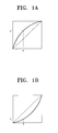
- the ABL circuit is used to maintain a steady brightness suitable for high performance image processing. For example, with the CRT, the brightness of the screen varies in proportion to a beam current flowing in the CRT. If a beam having an intensity greater than a predetermined level flows in the CRT, the brightness of the image becomes saturated and consequently the life-span of the CRT is shortened. On the other hand, if a beam current having an intensity less than the predetermined level flows, the ability to recognise the image reproduced by the CRT is deteriorated. To prevent this, the ABL circuit is applied to control the overflow or underflow of the beam. In other words, in the case of underflow in which the recognition ability of the reproduced image is deteriorated, a mapping function as shown in Figure 1A is used to increase the beam current and thus the luminance.
- a mapping function as shown in Figure 1B is used to adjust the current beam so as to protect the CRT and to enhance the image recognition ability.
- the ABL is used in CRTs that have brightness determined by a beam current. Therefore, the known method for adjusting the brightness of the dark or white area on the CRT screen is not appropriate for a thin display having no beam current. Moreover, the ABL used in the CRT uses a fixed mapping function without consideration of the average brightness of the input image. Accordingly, there is another disadvantage in that the dynamic range for the gradation display may be reduced in processing a high definition image. It is an object of the present invention to improve the luminance control in a thin display.
- the present invention relates to a method of controlling luminance.
- a method according to the present invention is characterised by generating a representation of the frequency of occurrence for the possible pixel luminance values of an input image signal, calculating upper and lower threshold values, adjusting the represented frequency of occurrence values in dependence on the upper and lower threshold values, generating a representation of a cumulative density function from the adjusted representation of the frequency of occurrence, normalising the representation of the cumulative density function to compensate for said adjusting, and mapping the luminance of each pixel in the input image signal in accordance with the normalised representation of the cumulative density function.
- the present invention also relates to a luminance controller.
- a luminance controller is characterised by means for generating a representation of the frequency of occurrence for the possible pixel luminance values of an input image signal, means for calculating upper and lower threshold values, adjusting means for adjusting the represented frequency of occurrence values in dependence on the upper and lower threshold values, means for generating a representation of a cumulative density function from the adjusted representation of the frequency of occurrence, means for normalising the representation of the cumulative density function to compensate for said adjusting and means for mapping the luminance of each pixel in the input image signal in accordance with the normalised representation of the cumulative density function.
- the image enhancing apparatus comprises a PDF calculation unit 100, an average brightness calculation unit 110, an input unit 120, an adaptive overflow threshold calculation unit 130, a BUBO unit 140, a CDF calculation unit 150, an adaptive gain calculation unit 160, a CDF compensation unit 170 and a mapping unit 180.
- the PDF calculation unit 100 detects the luminance value for each pixel forming an input image.
- the PDF calculation unit 100 also calculates a probability density function (hereinafter, referred to as "PDF") based on the detected luminance values.
- PDF indicates the probability that an irregular signal has a certain value.
- the average brightness calculation unit 110 calculates a mean average brightness of the input image using the PDF that is calculated in the PDF calculation unit 100.
- the input unit 120 has a scale factor input which is used for the calculation of an overflow threshold and the gain by a user. This will be described later.
- the adaptive overflow threshold calculation unit 130 analyzes the average brightness of the input image and calculates the overflow threshold accordingly.
- the BUBO unit 140 adjusts the PDF which is calculated using the overflow threshold and a predetermined underflow threshold.
- the CDF calculation unit 150 calculates a cumulative distribution function (hereinafter, referred to as "CDF") using the adjusted PDF.
- the adaptive gain calculation unit 160 calculates the gain to be used for compensation in the CDF compensation unit 170.
- the CDF compensation unit 170 compensates for the influence that the BUBO unit 140 has on the CDF. This compensation is calculated according to the PDF adjustment.
- the mapping unit 180 enhances the image by adjusting a pixel value of the input image by using the compensated CDF in the CDF compensation unit 170 as a mapping function.
- the PDF calculation unit 100 calculates the PDF of the input image (S200).
- the PDF is calculated by detecting the luminance value of each pixel forming the input image and the number of pixels that correspond to each luminance value within the luminance value of the detected pixel is counted.
- the average brightness calculation unit 110 calculates the average brightness of the input image based on the calculated PDF (S205).
- the adaptive overflow threshold calculation unit 130 uses the average brightness calculated in the average brightness calculation unit 110 and a first scale factor input by the user through the input unit 120 so as to calculate the variable overflow threshold in accordance with the following formula 1 (S210): wherein, 'mean' denotes the average brightness of the input image, 'sf1' denotes the first scale factor, 'th_o_high' denotes the fixed overflow threshold and 'th_low' denotes a reference value for dividing the PDF of the input image into the dark area (or the light area) and the intermediate area.
- the BUBO unit 140 detects the overflow and the underflow, using the calculated overflow threshold and the predetermined underflow threshold, which is determined experimentally, and accordingly adjusts the calculated PDF (S215).
- the BUBO unit 140 uses the calculated overflow threshold and the predetermined underflow threshold so as to detect the overflow and the underflow from the calculated PDF in accordance with the following formula 2: wherein, 'th_u' denotes the underflow threshold.
- the BUBO unit 140 Upon detecting the overflow and the underflow, the BUBO unit 140 removes values in the calculated PDF that exceed the overflow threshold and adjusts values less than the underflow threshold to the underflow threshold in accordance with the following formula 3:
- 'A' indicates the overflow threshold, and the shaded areas indicate the values exceeding the overflow threshold.
- Figure 4B shows the PDF after having removed the values exceeding the overflow threshold. Though Figures 4A and 4B show only the values exceeding the overflow threshold for convenience, the values less than the underflow threshold may be set equal to the underflow threshold through the method described above.
- the CDF calculation unit 150 calculates the CDF with respect to the adjusted PDF in accordance with the following formula 4 (S220):
- the CDF compensation unit 170 compensates for the influence that the BUBO unit 140 has on the CDF because of the PDF adjustment.
- the compensation is then performed using the following formulas 6.
- Figure 5A explains the formulas. wherein, 'C' denotes the number of pixels divided by 'N-1'.
- a line 'k' may be formed having a line adaptive to the average brightness of the input image or as a non-linear function.
- the line drawn to the normal scale may be formed as the non-linear function adapted to the average brightness of the input image.
- the non-linear function may be approximated to the line drawn to normal scale.
- the first formula may be added to the gain calculated in the adaptive gain calculation unit 160 in order to increase the difference between the line and the CDF, as shown in formula 7 and Figure 5B.
- cdf [ k ] gain ⁇ [ cdf [ k ] - cdf ( N -1) * k ( N -1) ]+ k
- the image is enhanced by adaptively improving the gradation display of the dark area in accordance with the input image signal.
- the dark area i.e., a black area is taken as the example
- the method can be also applied to a white area.
- the method according to an embodiment of the present invention is capable of enhancing the image by adaptively improving the gradation display of the dark or light area according to the input image.
Landscapes
- Engineering & Computer Science (AREA)
- Physics & Mathematics (AREA)
- General Physics & Mathematics (AREA)
- Theoretical Computer Science (AREA)
- Computer Hardware Design (AREA)
- Image Processing (AREA)
- Facsimile Image Signal Circuits (AREA)
- Liquid Crystal Display Device Control (AREA)
- Picture Signal Circuits (AREA)
- Control Of Indicators Other Than Cathode Ray Tubes (AREA)
- Controls And Circuits For Display Device (AREA)
Applications Claiming Priority (2)
| Application Number | Priority Date | Filing Date | Title |
|---|---|---|---|
| KR2003048464 | 2003-07-15 | ||
| KR1020030048464A KR20050008391A (ko) | 2003-07-15 | 2003-07-15 | 화질개선장치 및 그 방법 |
Publications (1)
| Publication Number | Publication Date |
|---|---|
| EP1498846A2 true EP1498846A2 (fr) | 2005-01-19 |
Family
ID=33476025
Family Applications (1)
| Application Number | Title | Priority Date | Filing Date |
|---|---|---|---|
| EP04103396A Withdrawn EP1498846A2 (fr) | 2003-07-15 | 2004-07-15 | Dispositif de contrôle de luminance |
Country Status (5)
| Country | Link |
|---|---|
| US (1) | US20050013503A1 (fr) |
| EP (1) | EP1498846A2 (fr) |
| JP (1) | JP3961515B2 (fr) |
| KR (1) | KR20050008391A (fr) |
| CN (1) | CN1303812C (fr) |
Cited By (1)
| Publication number | Priority date | Publication date | Assignee | Title |
|---|---|---|---|---|
| US7388998B2 (en) * | 2003-07-04 | 2008-06-17 | Ed-Tech Co., Ltd. | Apparatus and method for controlling brightness of moving image signals in real time |
Families Citing this family (19)
| Publication number | Priority date | Publication date | Assignee | Title |
|---|---|---|---|---|
| KR100602583B1 (ko) * | 2004-07-09 | 2006-08-25 | 최명렬 | 평판표시패널의 적응형 콘트라스트 조절장치 |
| KR100755676B1 (ko) | 2005-08-26 | 2007-09-05 | 삼성전자주식회사 | 밝기 향상 및 전력 제어를 지원하는 영상 표시 장치 및방법 |
| US7746411B1 (en) * | 2005-12-07 | 2010-06-29 | Marvell International Ltd. | Color management unit |
| KR100756318B1 (ko) * | 2006-01-16 | 2007-09-06 | 삼성전자주식회사 | 이득 조절 가능한 절단 빈도함수 평활화를 이용한 영상처리 방법 및 시스템 |
| US7756330B2 (en) * | 2006-07-27 | 2010-07-13 | Eastman Kodak Company | Producing an extended dynamic range digital image |
| KR100849845B1 (ko) * | 2006-09-05 | 2008-08-01 | 삼성전자주식회사 | 영상 보정 방법 및 장치 |
| KR101282245B1 (ko) * | 2006-09-29 | 2013-07-10 | 삼성전자주식회사 | 디스플레이장치 및 그 제어방법 |
| TWI384437B (zh) | 2006-12-18 | 2013-02-01 | Sony Corp | An image signal processing device, an image signal processing method, and a computer program product |
| JP2008178075A (ja) | 2006-12-18 | 2008-07-31 | Sony Corp | 表示制御装置、表示制御方法、及びプログラム |
| US8169431B2 (en) * | 2007-12-26 | 2012-05-01 | Sharp Laboratories Of America, Inc. | Methods and systems for image tonescale design |
| CN102780889B (zh) * | 2011-05-13 | 2015-04-01 | 中兴通讯股份有限公司 | 视频图像处理方法、装置及设备 |
| JP5603888B2 (ja) * | 2012-01-06 | 2014-10-08 | 株式会社アドバンテスト | 算出装置、測定装置、電子デバイス、プログラム、記憶媒体および算出方法 |
| CN104282291A (zh) * | 2013-07-08 | 2015-01-14 | 联咏科技股份有限公司 | 图像处理装置及应用其的图像处理方法 |
| JP6241192B2 (ja) * | 2013-10-18 | 2017-12-06 | 株式会社リコー | 画像処理装置、画像処理システム、画像処理方法、プログラム及び記録媒体 |
| CN106531050B (zh) * | 2016-12-27 | 2020-02-18 | 上海天马有机发光显示技术有限公司 | 显示面板的灰阶补偿方法、装置和系统 |
| CN111865808B (zh) * | 2019-04-25 | 2022-05-13 | 华为技术有限公司 | 一种数据流控制方法及装置 |
| KR102745490B1 (ko) * | 2020-04-03 | 2024-12-24 | 삼성디스플레이 주식회사 | 표시 패널의 얼룩 보정 방법, 이를 포함하는 표시 패널의 구동 방법 및 이를 수행하는 표시 장치 |
| CN111445879B (zh) * | 2020-04-30 | 2022-04-26 | 京东方科技集团股份有限公司 | 动态局部调光显示控制方法及装置、显示装置 |
| CN112287971A (zh) * | 2020-09-27 | 2021-01-29 | 北京航天自动控制研究所 | 一种测试数据自适应动态阈值确定方法 |
Family Cites Families (12)
| Publication number | Priority date | Publication date | Assignee | Title |
|---|---|---|---|---|
| JP3221967B2 (ja) * | 1993-03-31 | 2001-10-22 | 富士写真フイルム株式会社 | 撮像装置 |
| US5943032A (en) * | 1993-11-17 | 1999-08-24 | Fujitsu Limited | Method and apparatus for controlling the gray scale of plasma display device |
| KR0142290B1 (ko) * | 1993-11-24 | 1998-06-15 | 김광호 | 장면적응 영상개선방법 및 그 회로 |
| GB9407335D0 (en) * | 1994-04-12 | 1994-06-08 | Smithkline Beecham Corp | Method of treatment |
| JP3130266B2 (ja) * | 1996-03-09 | 2001-01-31 | 三星電子株式会社 | 平均分離ヒストグラム等化を用いる映像改善方法及びその回路 |
| KR100200628B1 (ko) * | 1996-09-30 | 1999-06-15 | 윤종용 | 화질 개선 회로 및 그 방법 |
| US6392993B1 (en) * | 1998-06-29 | 2002-05-21 | Microsoft Corporation | Method and computer program product for efficiently and reliably sending small data messages from a sending system to a large number of receiving systems |
| KR100322596B1 (ko) * | 1998-12-15 | 2002-07-18 | 윤종용 | 입력 영상의 밝기를 유지하는 화질 개선 장치 및 그 방법 |
| US6774942B1 (en) * | 2000-08-17 | 2004-08-10 | Exar Corporation | Black level offset calibration system for CCD image digitizer |
| US7064785B2 (en) * | 2002-02-07 | 2006-06-20 | Eastman Kodak Company | Apparatus and method of correcting for dark current in a solid state image sensor |
| EP1367558A3 (fr) * | 2002-05-29 | 2008-08-27 | Matsushita Electric Industrial Co., Ltd. | Dispositif et procédé de visualisation d'image avec réglage de la luminance d'une source de lumière |
| JP2003345315A (ja) * | 2002-05-30 | 2003-12-03 | Fujitsu Ltd | 信号処理部及び液晶表示装置 |
-
2003
- 2003-07-15 KR KR1020030048464A patent/KR20050008391A/ko not_active Withdrawn
-
2004
- 2004-07-13 JP JP2004206166A patent/JP3961515B2/ja not_active Expired - Fee Related
- 2004-07-14 CN CNB2004100688821A patent/CN1303812C/zh not_active Expired - Fee Related
- 2004-07-15 US US10/891,088 patent/US20050013503A1/en not_active Abandoned
- 2004-07-15 EP EP04103396A patent/EP1498846A2/fr not_active Withdrawn
Cited By (1)
| Publication number | Priority date | Publication date | Assignee | Title |
|---|---|---|---|---|
| US7388998B2 (en) * | 2003-07-04 | 2008-06-17 | Ed-Tech Co., Ltd. | Apparatus and method for controlling brightness of moving image signals in real time |
Also Published As
| Publication number | Publication date |
|---|---|
| CN1303812C (zh) | 2007-03-07 |
| JP3961515B2 (ja) | 2007-08-22 |
| US20050013503A1 (en) | 2005-01-20 |
| KR20050008391A (ko) | 2005-01-21 |
| JP2005039817A (ja) | 2005-02-10 |
| CN1578438A (zh) | 2005-02-09 |
Similar Documents
| Publication | Publication Date | Title |
|---|---|---|
| EP1498846A2 (fr) | Dispositif de contrôle de luminance | |
| US7286716B2 (en) | Image quality enhancement circuit and method using inter-frame correlativity | |
| US6507668B1 (en) | Image enhancing apparatus and method of maintaining brightness of input image | |
| JP4687526B2 (ja) | 動画像表示装置および動画像表示方法 | |
| US7454137B2 (en) | Scene adaptive power control apparatus and method thereof | |
| US8912998B2 (en) | Luminance control device, display apparatus using the same, luminance control method and luminance control program | |
| US9582866B2 (en) | Adaptive contrast enhancement apparatus and method | |
| US8044978B2 (en) | Image display apparatus and high quality image providing method thereof | |
| JP4799890B2 (ja) | プラズマディスプレイパネルの表示方法 | |
| US9846925B2 (en) | Defog system and defog method | |
| JP5206731B2 (ja) | プロジェクターおよび画像投写方法 | |
| US9659519B2 (en) | Video-display control device for correcting a video signal and controlling a backlight | |
| KR100803545B1 (ko) | 플라즈마 디스플레이 패널의 구동장치 및 그 구동방법 | |
| US20050190121A1 (en) | Contrast compensating apparatus for PDP module and method thereof | |
| EP2811481B1 (fr) | Dispositif de commande d'affichage vidéo | |
| KR100388582B1 (ko) | 평판 디스플레이 패널의 화질 조정 방법 | |
| US20110085086A1 (en) | Method for adaptive noise reduction and apparatus thereof | |
| JP2006270417A (ja) | 映像信号処理方法及び映像信号処理装置 | |
| JP2006119200A (ja) | 映像表示装置 | |
| US20050265599A1 (en) | Methods and devices for controlling image contrast | |
| KR100480166B1 (ko) | 다이나믹 레인지 확대방법을 이용한 플라즈마 디스플레이패널의 컬러 보정 장치 및 방법 |
Legal Events
| Date | Code | Title | Description |
|---|---|---|---|
| PUAI | Public reference made under article 153(3) epc to a published international application that has entered the european phase |
Free format text: ORIGINAL CODE: 0009012 |
|
| AK | Designated contracting states |
Kind code of ref document: A2 Designated state(s): AT BE BG CH CY CZ DE DK EE ES FI FR GB GR HU IE IT LI LU MC NL PL PT RO SE SI SK TR |
|
| AX | Request for extension of the european patent |
Extension state: AL HR LT LV MK |
|
| STAA | Information on the status of an ep patent application or granted ep patent |
Free format text: STATUS: THE APPLICATION IS DEEMED TO BE WITHDRAWN |
|
| 18D | Application deemed to be withdrawn |
Effective date: 20100202 |