EP1498847A2 - Procédé pour la détermination d'une carte de profondeur d'une image numérique - Google Patents
Procédé pour la détermination d'une carte de profondeur d'une image numérique Download PDFInfo
- Publication number
- EP1498847A2 EP1498847A2 EP04076850A EP04076850A EP1498847A2 EP 1498847 A2 EP1498847 A2 EP 1498847A2 EP 04076850 A EP04076850 A EP 04076850A EP 04076850 A EP04076850 A EP 04076850A EP 1498847 A2 EP1498847 A2 EP 1498847A2
- Authority
- EP
- European Patent Office
- Prior art keywords
- image
- plane
- case
- depth
- threshold
- Prior art date
- Legal status (The legal status is an assumption and is not a legal conclusion. Google has not performed a legal analysis and makes no representation as to the accuracy of the status listed.)
- Withdrawn
Links
Images


Classifications
-
- G—PHYSICS
- G06—COMPUTING OR CALCULATING; COUNTING
- G06T—IMAGE DATA PROCESSING OR GENERATION, IN GENERAL
- G06T7/00—Image analysis
- G06T7/50—Depth or shape recovery
- G06T7/536—Depth or shape recovery from perspective effects, e.g. by using vanishing points
Definitions
- the present invention relates to the processing of digital images and, more particularly, to a method of obtaining a depth map from a digital image of a three-dimensional scene.
- the relative depths of a pixel is understood as the distance of the point of the three-dimensional scene represented by the pixel from a reference plane that, as a general rule, coincides with the plane of the image.
- the depth map is constituted by a grey-scale image in which each pixel is assigned a value according to its depth. It is usually assumed that the higher the grey-value (lighter grey) associated with a pixel, the nearer is it situated to the reference plane.
- a depth map makes it possible to obtain from the starting image a second image that, together with the starting image, constitutes a stereoscopic pair providing a three-dimensional vision of the scene.
- One object of the present invention is to propose a method that will make it possible to produce a depth map from a single image with short processing times and to a large extent in an automatic manner.
- a particular object of the present invention is to propose a method for obtaining a depth map of a three-dimensional scene containing geometric objects in a completely automatic manner
- Another object is to propose a method of obtaining a depth map from a digital image of any three-dimensional scene, i.e. a landscape scene, or a scene that essentially contains geometric objects, or a scene that contains both a landscape and geometric objects.
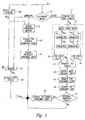
- a digital image 1 of a three-dimensional scene, a colour image for example is analyzed (in a decisional block 10) to determine the category or class to which it belongs.
- This operation may be carried out by an operator on the basis of observing the image or may be carried out in an automatic manner.
- a method of automatically carrying out the operation is described, for example, in an Italian patent application filed by the applicant on the same day as the present application and bears the title "Metodo per class NEED un'immagine digitale", designating the same inventors as are designated in the present application.
- the analysis of the scene may show that the image falls into a category of images substantially devoid of geometric objects, i.e. an image category of "landscapes” or a category of images that contain geometric images, indicated by "Other” in Figure 1.
- image category of "landscapes” or a category of images that contain geometric images indicated by "Other” in Figure 1.
- geometric images is intended to identify objects or structures defined by at least a horizontal plane or at least a vertical plane in the real scene.
- this process comprises the application of an operator, known as the Sobel operator (Block 13), two normalization or scaling operations (Blocks 14) and a threshold segmentation or threshold operation (Block 15).
- the Sobel operator carries out a measurement of the two-dimensional space gradient to highlight the regions of a high spatial frequency that correspond to the outlines of the objects in the image.
- I Sx I * S x
- I Sy I * S y
- Each Block 16 is constituted by a low-pass filter that operates by means of the application of the convolution of a Mask A of size 5x5 with appropriate coefficients. It is used to eliminate possible disturbance peaks present in I Sx and I Sy .
- Blocks 15 and 16 are applied to a straight-line-search block 17 that carries out a series of operations based on a procedure known as the Hough transform.
- the Hough transform makes it possible to identify various geometric configurations, like lines, circumferences or any curve that can be represented in parametric form, but in the present application it is used to identify only straight lines.
- r and ⁇ defines a point in a parameter space or Hough space. Each point of this space therefore identifies a straight line of the Cartesian plane x,y.
- the check consists of observing for each pixel how many pixels in a predetermined surrounding area belong to the straight line that has just been found (it should be remembered that to verify whether or not a point belongs to a given straight line one substitutes the coordinates of the point in the equation of the straight line and observes whether equality is effectively obtained). If this number is greater than a predetermined threshold value, the consistency check is successful and the pair (m,q) can at last be memorized in the accumulation matrix.
- the phase of memorizing the pair (m,q) envisages first the quantization of these two values and then the updating of the corresponding value of the accumulation matrix ACC.
- m there has been conceived a scale of values subdivided with an irregular interval. This interval becomes gradually smaller as zero is approached and becomes larger when one moves away from zero. All this in order to have greater detail in the range of values of m comprised between -1 and 1, where a minute variation implies straight lines with widely different slopes. To resolve the problem of the greatly inclined straights, which are associated with a large angular coefficient, these are represented by a value of m equal to ⁇ 8, having verified that these values well approximate these slopes.
- the value scale of q is obtained with a regular interval.
- the N straights obtained are candidates for becoming the looked for vanishing lines. This fact derives from having noted that in an image with marked geometric characteristic the vanishing lines are the lines that occur most frequently, because they coincide with the greater part of the outlines of the objects present in the image..
- a statistical approach is adopted for finding the vanishing point.
- the idea is that the candidate vanishing lines intersect with greater frequency in the zone containing the vanishing point.
- the looked-for vanishing point will be the point having the largest number of "neighbours", that is to say, it will coincide with the accumulation point of the entire image.
- the next operation is the search for the vanishing lines (Block 20).
- each of these straights is chosen as a vanishing line if, together with another straight, it had previously generated an intersection point falling within the neighbourhood of the vanishing point. In case the straight in question has not generated any intersections "near" the vanishing point it will be discarded. In the light of these considerations, one can affirm that the number of vanishing lines may vary between a minimum value equal to 2 and a maximum value equal to N.
- the position of the found vanishing point is examined (Block 21) to verify whether it is situated outside or inside a central image zone of predetermined dimensions. If it is situated outside, one passes directly to the successive phase of assigning depth levels, otherwise one performs an intermediate search operation of searching for other vanishing lines (Block 22). This operation is necessary in order to render possible a correct identification of the planes present in the image in this particular position of the vanishing point, as will be explained later on. In particular, for every contemplated angular coefficient there is calculated the ordinate at the origin of the straight that has this angular coefficient and passes through the vanishing point.
- the accumulation matrix ACC of the parameters is analyzed, checking whether the pair (m,q) in question had been found previously in the search for straight lines of Block 17. If the check yields a positive result, the straight identified by the present pair of parameters is added to the set of vanishing lines.
- the information I vld (x,y) relating to the vanishing point and the vanishing lines is utilized for assigning a depth level to each pixel of the image, thereby obtaining a depth map of the starting image I(x,y). Similar information I vld (x,y) may be generated also in the case in which the analysis of the image carried out in Block 10 leads to the conclusion that the image belongs to the "Landscape" category. In that case there is identified a vanishing point, i.e. a central point of the image that is situated on the line of the horizon, and there is identified the plane passing through the line of the horizon in which there are drawn two fictitious vanishing lines that intersect at the central vanishing point.
- the starting image is subdivided into a multiplicity of homogeneous regions, associating each pixel with a region on the basis of at least one of the digital values of the given pixel, for example on the basis of its chromatic characteristics (Block 30).
- the regions are: "Sky”, “very distant mountain”, “Distant mountain”, “Nearby mountain”, “land” and "other”.
- each region is labelled with a predetermined grey value and, more precisely, in such a manner that the regions closest to the observer (image plane) are labelled with a clearer grey level than that of the more distant regions.
- This partial map, indicated by M2 constitutes the output of Block 30, the one that subdivides into regions, and an input for a Block 31, and a Block 35.
- Block 31 identifies the region adjacent to the union between the region "Land” and the region "Other”. This information will be exploited in Block 34 to establish which is to be the lowest grey level to be used in the depth gradient. For example, in the case in which the adjacent region is "Sky”, this is identified by a grey level equal to 0. In that case a gradient up to a grey level equal to 32 will be drawn in Block 34, while in the case of "Nearby mountain” the lowest grey level will be 100.
- the central vanishing point is identified in Block 32.
- the following criterion is adopted to this end:
- Two vanishing lines intersecting at the vanishing point and having predetermined angular coefficients are created in Block 33.
- the information relating to the vanishing point and the fictitious vanishing lines are applied as input to a Block 34 for assigning depth levels.
- the assignment process commences with the analysis of the position of the vanishing point with respect to the image. In particular, starting from its coordinates, the analysis seeks to ascertain which of the following conditions is satisfied:
- the lines are classified into 4 classes by means of the following parameters:
- the first parameter which represents the intersection point of the vanishing line with the border of the image, indicates whether the origin of the vanishing line is situated in a position of which the coordinate Y o is smaller or greater than the coordinate Y vp of the vanishing point.
- Figures 4 and 5 illustrate, respectively, a possible Left Case situation and a Right Case situation.
- the vanishing lines can belong only to Classes 1 and 4 in the Left Case and only to Classes 2 and 3 in the Right Case.
- the lines are ordered according to growing values of the angular coefficient and two lines are selected from among them in such a manner that:
- a third vanishing line is also identified in such a manner that:
- the angular coefficients m1, m2, m3 are analyzed for the generation of these planes and the planes (horizontal or vertical planes or both) are obtained on the basis of their values.
- Figures 6 and 7 illustrate, respectively, a possible situation of the Up Case and another of the Down Case.
- the vanishing lines can belong only to Classes 3 and 4 in the Up Case and only to Classes 1 and 2 in the Down Case.
- the lines are subdivided into:
- a third vanishing line is also identified in such a manner that:
- Figure 8 illustrates a possible situation in which the vanishing point is in a central zone of the image (Inside Case).
- the vanishing lines can belong to all the classes.
- the next step consists of subdividing the vanishing lines into: Class 1, Class 2, Class 3 and Class 4 .
- a grey level corresponding to a depth level is assigned to each pixel of the gradient planes.
- the assignment is made for rows in the horizontal gradient planes and for columns in the vertical planes with the depth level increasing in the direction of the vanishing point, starting from a line of the image that is, respectively, horizontal or vertical, in this example one of the border lines of the image.
- the law of assigning the depth is approximated by a curve that is sectionally linear and depends on the values of the angular coefficients m1 and m2 of the straights that generate the plane.
- D min q2/m2-q1/m1
- D max (H-1-q1) /m1- (H-1-q2) /m2;
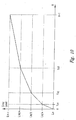
- Figure 10 shows a qualitative graph of the sectionally linear curve relating to the case of Figure 9; the ordinates represent the grey value assigned to each row Y i of the image.
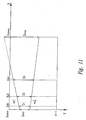
- D min q1-q2
- D max (m2-m1) (W-1)+q2-q1;
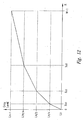
- Figure 12 shows a qualitative graph of the sectionally linear curve relating to the case of Figure 11; the ordinates represent the grey value assigned to every column X i of the image.
- Block 35 represents the last operation of the method in accordance with the invention. It receives as input M 1 (x,y) and M 2 (x,y) to generate the final depth map M(x,y) as output. It should be noted that M 1 (x,y) can be a partial depth map generated for an image classified as “Landscape” or as "Other”.
- region region cardinality region region cardinality .... . 1 2 10.1.
- region indicates whether the type of region identified during the scanning is "Sky” or "Non-sky” and the region cardinality indicates the number of consecutive pixels forming part of the region.
- Non-sky represents any one of the regions defined above, though with the obvious exception of the region "Sky”.
- the structure is dynamic: a new element is added every time that a new region is identified during the scanning of the column.
- threshold _1 0.01
- threshold _2 0.05
- the depth map obtained by means of the method described above is derived from a single image and therefore from a set of starting data that is reduced as compared with the techniques that call for the analysis of several images, has a lower resolution than the resolution of the starting image, can be greatly compressed, enjoys perfect two-dimensional compatibility and makes it possible to generate stereoscopic pairs in real time. It can be obtained in a completely automatic manner when the choice of the category to which the image belongs is made in accordance with the cited patent application filed on the same day as the present application or in a partially automatic manner if the choice of category calls for the intervention of an operator.
- the method in accordance with the invention may be put into practice with many variants with respect to the example described hereinabove.
- it can be applied in such a manner as to find several vanishing points in order to obtain a more detailed depth map, especially when the map is to be used for converting two-dimensional images into three-dimensional images.
Landscapes
- Engineering & Computer Science (AREA)
- Computer Vision & Pattern Recognition (AREA)
- Physics & Mathematics (AREA)
- General Physics & Mathematics (AREA)
- Theoretical Computer Science (AREA)
- Image Analysis (AREA)
- Image Processing (AREA)
- Length Measuring Devices By Optical Means (AREA)
Applications Claiming Priority (2)
| Application Number | Priority Date | Filing Date | Title |
|---|---|---|---|
| ITRM20030345 | 2003-07-15 | ||
| IT000345A ITRM20030345A1 (it) | 2003-07-15 | 2003-07-15 | Metodo per ricavare una mappa di profondita' |
Publications (2)
| Publication Number | Publication Date |
|---|---|
| EP1498847A2 true EP1498847A2 (fr) | 2005-01-19 |
| EP1498847A3 EP1498847A3 (fr) | 2006-02-15 |
Family
ID=29765915
Family Applications (1)
| Application Number | Title | Priority Date | Filing Date |
|---|---|---|---|
| EP04076850A Withdrawn EP1498847A3 (fr) | 2003-07-15 | 2004-06-25 | Procédé pour la détermination d'une carte de profondeur d'une image numérique |
Country Status (3)
| Country | Link |
|---|---|
| US (1) | US7668377B2 (fr) |
| EP (1) | EP1498847A3 (fr) |
| IT (1) | ITRM20030345A1 (fr) |
Cited By (5)
| Publication number | Priority date | Publication date | Assignee | Title |
|---|---|---|---|---|
| EP2194504A1 (fr) * | 2008-12-02 | 2010-06-09 | Koninklijke Philips Electronics N.V. | Génération d'une carte de profondeur |
| CN101751664B (zh) * | 2008-12-02 | 2013-04-17 | 奇景光电股份有限公司 | 立体深度资讯的产生系统及产生方法 |
| US8638986B2 (en) | 2011-04-20 | 2014-01-28 | Qualcomm Incorporated | Online reference patch generation and pose estimation for augmented reality |
| ITVI20120303A1 (it) * | 2012-11-09 | 2014-05-10 | St Microelectronics Srl | Metodo per rilevare una linea retta in un'immagine digitale |
| US9224205B2 (en) | 2012-06-14 | 2015-12-29 | Qualcomm Incorporated | Accelerated geometric shape detection and accurate pose tracking |
Families Citing this family (32)
| Publication number | Priority date | Publication date | Assignee | Title |
|---|---|---|---|---|
| EP1897056B1 (fr) * | 2005-06-23 | 2016-08-10 | Koninklijke Philips N.V. | Échange combiné de données d'image et de données apparentées |
| KR100873638B1 (ko) * | 2007-01-16 | 2008-12-12 | 삼성전자주식회사 | 영상 처리 방법 및 장치 |
| KR101388133B1 (ko) * | 2007-02-16 | 2014-04-23 | 삼성전자주식회사 | 2차원 실사 영상으로부터 3차원 모델을 생성하는 방법 및장치 |
| US8213711B2 (en) * | 2007-04-03 | 2012-07-03 | Her Majesty The Queen In Right Of Canada As Represented By The Minister Of Industry, Through The Communications Research Centre Canada | Method and graphical user interface for modifying depth maps |
| US8488868B2 (en) * | 2007-04-03 | 2013-07-16 | Her Majesty The Queen In Right Of Canada, As Represented By The Minister Of Industry, Through The Communications Research Centre Canada | Generation of a depth map from a monoscopic color image for rendering stereoscopic still and video images |
| KR100918862B1 (ko) * | 2007-10-19 | 2009-09-28 | 광주과학기술원 | 참조영상을 이용한 깊이영상 생성방법 및 그 장치, 생성된깊이영상을 부호화/복호화하는 방법 및 이를 위한인코더/디코더, 그리고 상기 방법에 따라 생성되는 영상을기록하는 기록매체 |
| US8508550B1 (en) * | 2008-06-10 | 2013-08-13 | Pixar | Selective rendering of objects |
| WO2009157707A2 (fr) * | 2008-06-24 | 2009-12-30 | Samsung Electronics Co,. Ltd. | Procédé et appareil de traitement d'image |
| US20090317062A1 (en) * | 2008-06-24 | 2009-12-24 | Samsung Electronics Co., Ltd. | Image processing method and apparatus |
| KR101539935B1 (ko) * | 2008-06-24 | 2015-07-28 | 삼성전자주식회사 | 3차원 비디오 영상 처리 방법 및 장치 |
| US20090315980A1 (en) * | 2008-06-24 | 2009-12-24 | Samsung Electronics Co., | Image processing method and apparatus |
| WO2010085186A1 (fr) * | 2009-01-21 | 2010-07-29 | Telefonaktiebolaget L M Ericsson (Publ) | Génération d'étiquettes d'annotation sur la base de métadonnées multimodales et de descripteurs sémantiques structurés |
| JP5541914B2 (ja) * | 2009-12-28 | 2014-07-09 | オリンパス株式会社 | 画像処理装置、電子機器、プログラム及び内視鏡装置の作動方法 |
| US8520935B2 (en) * | 2010-02-04 | 2013-08-27 | Sony Corporation | 2D to 3D image conversion based on image content |
| US9053562B1 (en) | 2010-06-24 | 2015-06-09 | Gregory S. Rabin | Two dimensional to three dimensional moving image converter |
| US8848038B2 (en) * | 2010-07-09 | 2014-09-30 | Lg Electronics Inc. | Method and device for converting 3D images |
| US8571314B2 (en) | 2010-09-02 | 2013-10-29 | Samsung Electronics Co., Ltd. | Three-dimensional display system with depth map mechanism and method of operation thereof |
| KR101638919B1 (ko) * | 2010-09-08 | 2016-07-12 | 엘지전자 주식회사 | 이동 단말기 및 이동 단말기의 제어방법 |
| TW201220253A (en) * | 2010-11-15 | 2012-05-16 | Inst Information Industry | Image calculation method and apparatus |
| US8824821B2 (en) | 2011-03-28 | 2014-09-02 | Sony Corporation | Method and apparatus for performing user inspired visual effects rendering on an image |
| TWI481262B (zh) | 2011-07-28 | 2015-04-11 | Ind Tech Res Inst | 影像編碼系統及影像編碼方法 |
| KR101862543B1 (ko) | 2011-09-08 | 2018-07-06 | 삼성전자 주식회사 | 깊이정보 생성장치, 깊이정보 생성방법 및 그 저장매체 |
| US9471988B2 (en) | 2011-11-02 | 2016-10-18 | Google Inc. | Depth-map generation for an input image using an example approximate depth-map associated with an example similar image |
| US9661307B1 (en) | 2011-11-15 | 2017-05-23 | Google Inc. | Depth map generation using motion cues for conversion of monoscopic visual content to stereoscopic 3D |
| US8897542B2 (en) * | 2011-12-15 | 2014-11-25 | Sony Corporation | Depth map generation based on soft classification |
| US9571810B2 (en) * | 2011-12-23 | 2017-02-14 | Mediatek Inc. | Method and apparatus of determining perspective model for depth map generation by utilizing region-based analysis and/or temporal smoothing |
| US9111350B1 (en) | 2012-02-10 | 2015-08-18 | Google Inc. | Conversion of monoscopic visual content to stereoscopic 3D |
| US8644596B1 (en) | 2012-06-19 | 2014-02-04 | Google Inc. | Conversion of monoscopic visual content using image-depth database |
| US9992021B1 (en) | 2013-03-14 | 2018-06-05 | GoTenna, Inc. | System and method for private and point-to-point communication between computing devices |
| US9674498B1 (en) | 2013-03-15 | 2017-06-06 | Google Inc. | Detecting suitability for converting monoscopic visual content to stereoscopic 3D |
| KR102815456B1 (ko) * | 2018-09-12 | 2025-05-30 | 삼성전자주식회사 | 영상 처리를 위한 학습 데이터 생성 방법, 영상 처리 방법, 및 그 장치들 |
| CN110717940B (zh) * | 2019-10-17 | 2024-11-15 | 南京鑫和汇通电子科技有限公司 | 一种基于深度图像的表面快速区分及特定目标识别方法 |
Family Cites Families (4)
| Publication number | Priority date | Publication date | Assignee | Title |
|---|---|---|---|---|
| JPS6476374A (en) * | 1987-09-18 | 1989-03-22 | Toshiba Corp | Depth map producing device |
| JPH1049704A (ja) * | 1996-07-31 | 1998-02-20 | Hitachi Ltd | 画像変換方法 |
| US6553138B2 (en) * | 1998-12-30 | 2003-04-22 | New York University | Method and apparatus for generating three-dimensional representations of objects |
| JP4573977B2 (ja) * | 1999-09-22 | 2010-11-04 | 富士重工業株式会社 | 監視システムの距離補正装置、および監視システムの消失点補正装置 |
-
2003
- 2003-07-15 IT IT000345A patent/ITRM20030345A1/it unknown
-
2004
- 2004-06-25 EP EP04076850A patent/EP1498847A3/fr not_active Withdrawn
- 2004-07-15 US US10/893,103 patent/US7668377B2/en active Active
Cited By (8)
| Publication number | Priority date | Publication date | Assignee | Title |
|---|---|---|---|---|
| EP2194504A1 (fr) * | 2008-12-02 | 2010-06-09 | Koninklijke Philips Electronics N.V. | Génération d'une carte de profondeur |
| WO2010064174A1 (fr) * | 2008-12-02 | 2010-06-10 | Koninklijke Philips Electronics N.V. | Génération d'une carte de profondeur |
| JP2012510660A (ja) * | 2008-12-02 | 2012-05-10 | コーニンクレッカ フィリップス エレクトロニクス エヌ ヴィ | 深度マップの生成 |
| CN101751664B (zh) * | 2008-12-02 | 2013-04-17 | 奇景光电股份有限公司 | 立体深度资讯的产生系统及产生方法 |
| US8638986B2 (en) | 2011-04-20 | 2014-01-28 | Qualcomm Incorporated | Online reference patch generation and pose estimation for augmented reality |
| US9224205B2 (en) | 2012-06-14 | 2015-12-29 | Qualcomm Incorporated | Accelerated geometric shape detection and accurate pose tracking |
| ITVI20120303A1 (it) * | 2012-11-09 | 2014-05-10 | St Microelectronics Srl | Metodo per rilevare una linea retta in un'immagine digitale |
| US9245200B2 (en) | 2012-11-09 | 2016-01-26 | Stmicroelectronics S.R.L. | Method for detecting a straight line in a digital image |
Also Published As
| Publication number | Publication date |
|---|---|
| ITRM20030345A0 (it) | 2003-07-15 |
| US7668377B2 (en) | 2010-02-23 |
| ITRM20030345A1 (it) | 2005-01-16 |
| US20050053276A1 (en) | 2005-03-10 |
| EP1498847A3 (fr) | 2006-02-15 |
Similar Documents
| Publication | Publication Date | Title |
|---|---|---|
| EP1498847A2 (fr) | Procédé pour la détermination d'une carte de profondeur d'une image numérique | |
| US7127107B2 (en) | Land partition data generating method and apparatus | |
| US8818077B2 (en) | Stereo image matching apparatus and method | |
| EP0796474B1 (fr) | Procede evitant les identifications redondantes (provoquees par des artefacts dans des images de colonies bacteriennes) | |
| DE69728127T2 (de) | Vorrichtung und Verfahren zur Extraktion eines Objekts in einem Bild | |
| US6970593B2 (en) | Stereo image processing apparatus and method of processing stereo image | |
| Wunderlich et al. | Areal Deformation Analysis from TLS Point Clouds-The Challenge/Flächenhafte Deformationsanalyse Aus TLS-Punktwolken-Die Herausforderung | |
| US20130223760A1 (en) | Microscopic image fusion method based on region growing | |
| CN110473221B (zh) | 一种目标物体自动扫描系统及方法 | |
| KR101549155B1 (ko) | 라이다 자료를 활용한 구조물의 직선경계 추출방법 | |
| CN113052754B (zh) | 一种图片背景虚化的方法及装置 | |
| JP4915737B2 (ja) | 画像解析システム、及び画像解析プログラム | |
| JP4747122B2 (ja) | 特定領域自動抽出システム、特定領域自動抽出方法、および、プログラム | |
| JPH05215547A (ja) | ステレオ画像間対応点決定方法 | |
| JP2791303B2 (ja) | 1つの連結領域が示すコロニーの個数を識別する識別方法及びこれを用いたコロニー計数装置 | |
| Sert | A new modified neutrosophic set segmentation approach | |
| JP3860540B2 (ja) | エントロピーフィルタ及び該フィルタを用いた領域抽出法 | |
| CN113792769A (zh) | 一种基于机场道面裂缝的检测方法 | |
| CN117218148B (zh) | 基于卫星图像的航道边界确定方法和系统、可读存储介质 | |
| CN116188497B (zh) | 立体遥感影像对生成dsm优化方法、装置、设备及存储介质 | |
| CN111815594A (zh) | 钢筋检测方法以及相关设备、装置 | |
| CN116630761A (zh) | 一种多视角卫星影像的数字表面模型融合方法及系统 | |
| CN114022434B (zh) | 一种护栏上下边线自动化提取方法及提取系统 | |
| Straub et al. | Concepts for internal and external evaluation of automatically delineated tree tops | |
| RU2580074C1 (ru) | Способ автоматической сегментации полутоновых сложноструктурированных растровых изображений |
Legal Events
| Date | Code | Title | Description |
|---|---|---|---|
| PUAI | Public reference made under article 153(3) epc to a published international application that has entered the european phase |
Free format text: ORIGINAL CODE: 0009012 |
|
| AK | Designated contracting states |
Kind code of ref document: A2 Designated state(s): AT BE BG CH CY CZ DE DK EE ES FI FR GB GR HU IE IT LI LU MC NL PL PT RO SE SI SK TR |
|
| AX | Request for extension of the european patent |
Extension state: AL HR LT LV MK |
|
| PUAL | Search report despatched |
Free format text: ORIGINAL CODE: 0009013 |
|
| AK | Designated contracting states |
Kind code of ref document: A3 Designated state(s): AT BE BG CH CY CZ DE DK EE ES FI FR GB GR HU IE IT LI LU MC NL PL PT RO SE SI SK TR |
|
| AX | Request for extension of the european patent |
Extension state: AL HR LT LV MK |
|
| 17P | Request for examination filed |
Effective date: 20060306 |
|
| AKX | Designation fees paid |
Designated state(s): DE FR GB IT |
|
| STAA | Information on the status of an ep patent application or granted ep patent |
Free format text: STATUS: THE APPLICATION IS DEEMED TO BE WITHDRAWN |
|
| 18D | Application deemed to be withdrawn |
Effective date: 20061114 |