EP1498859A2 - Machine de jeu - Google Patents
Machine de jeu Download PDFInfo
- Publication number
- EP1498859A2 EP1498859A2 EP04016823A EP04016823A EP1498859A2 EP 1498859 A2 EP1498859 A2 EP 1498859A2 EP 04016823 A EP04016823 A EP 04016823A EP 04016823 A EP04016823 A EP 04016823A EP 1498859 A2 EP1498859 A2 EP 1498859A2
- Authority
- EP
- European Patent Office
- Prior art keywords
- free game
- variable display
- winning combination
- symbol
- symbols
- Prior art date
- Legal status (The legal status is an assumption and is not a legal conclusion. Google has not performed a legal analysis and makes no representation as to the accuracy of the status listed.)
- Ceased
Links
- 239000004973 liquid crystal related substance Substances 0.000 description 50
- 238000000034 method Methods 0.000 description 41
- 230000008569 process Effects 0.000 description 41
- 230000001960 triggered effect Effects 0.000 description 24
- 238000005070 sampling Methods 0.000 description 20
- 238000003780 insertion Methods 0.000 description 19
- 230000037431 insertion Effects 0.000 description 19
- HVCNNTAUBZIYCG-UHFFFAOYSA-N ethyl 2-[4-[(6-chloro-1,3-benzothiazol-2-yl)oxy]phenoxy]propanoate Chemical compound C1=CC(OC(C)C(=O)OCC)=CC=C1OC1=NC2=CC=C(Cl)C=C2S1 HVCNNTAUBZIYCG-UHFFFAOYSA-N 0.000 description 18
- 241000167854 Bourreria succulenta Species 0.000 description 17
- 235000019693 cherries Nutrition 0.000 description 17
- 230000008859 change Effects 0.000 description 14
- 238000010276 construction Methods 0.000 description 10
- 238000001514 detection method Methods 0.000 description 10
- 238000009792 diffusion process Methods 0.000 description 7
- 230000000694 effects Effects 0.000 description 5
- 230000006870 function Effects 0.000 description 5
- 239000011521 glass Substances 0.000 description 5
- 239000002184 metal Substances 0.000 description 5
- 238000005286 illumination Methods 0.000 description 4
- 230000009286 beneficial effect Effects 0.000 description 3
- 238000010586 diagram Methods 0.000 description 3
- 239000011347 resin Substances 0.000 description 3
- 229920005989 resin Polymers 0.000 description 3
- 230000008901 benefit Effects 0.000 description 2
- 230000004397 blinking Effects 0.000 description 2
- 230000000717 retained effect Effects 0.000 description 2
- 239000002390 adhesive tape Substances 0.000 description 1
- 238000012986 modification Methods 0.000 description 1
- 230000004048 modification Effects 0.000 description 1
Images





Classifications
-
- G—PHYSICS
- G07—CHECKING-DEVICES
- G07F—COIN-FREED OR LIKE APPARATUS
- G07F17/00—Coin-freed apparatus for hiring articles; Coin-freed facilities or services
- G07F17/32—Coin-freed apparatus for hiring articles; Coin-freed facilities or services for games, toys, sports, or amusements
- G07F17/326—Game play aspects of gaming systems
- G07F17/3267—Game outcomes which determine the course of the subsequent game, e.g. double or quits, free games, higher payouts, different new games
-
- G—PHYSICS
- G07—CHECKING-DEVICES
- G07F—COIN-FREED OR LIKE APPARATUS
- G07F17/00—Coin-freed apparatus for hiring articles; Coin-freed facilities or services
- G07F17/32—Coin-freed apparatus for hiring articles; Coin-freed facilities or services for games, toys, sports, or amusements
Definitions
- the present invention relates to a gaming machine which gives predetermined benefit to a player when symbols on a plurality of variable display portions stop along a pay line.
- the present invention relates to a gaming machine with a display device capable of changing a number or shape of symbols which are variably displayed on variable display portions of the display device.
- Japanese unexamined Publication No. 11-244453 it is disclosed a slot machine which is constructed so that after a game is started, not only combination lottery of symbol marks formed on each of three reels is conducted but also lottery of pay lines is done.
- position and number of the pay lines becomes changeable against the combination of the symbol marks which are determined by the lottery and stopped and displayed.
- interest of the player for games can be continued till end of the game.
- winning probability of the combination of symbol marks can be raised.
- the predetermined combination (winning combination) can be obtained if the last only one symbol is in good order in the combination, concerning with the symbols of the reels which are automatically stopped and displayed along the pay line. That is to say, there are still many cases which do not reach to the winning combination by a narrow margin.
- the present invention has been done to accomplish the above problems and has an object to provide a gaming machine in which it can be realized a state that a specific symbol combination can be easily won by changing a use number of symbols variably displayed on variable display portions used in a game when a specific condition is realized.
- the present invention has another object to provide a gaming machine in which it can be realized a state that a specific symbol combination can be easily won by changing shapes of symbols variably displayed on variable display portions used in a game when a specific condition is realized.
- a gaming machine having a display device with a plurality of variable display portions on each of which symbols are variably displayed, a payout being given when the symbols variably displayed on each variable display portion are stopped along a pay line with a predetermined winning combination, the gaming machine comprising:
- the number of the symbols variably displayed on each of the variable display portions is determined by the symbol number controller and the lottery of the winning combination is conducted according to the number of the symbols determined by the symbol number controller. Therefore, the number of the symbols which are variably displayed on each of the variable display portions utilized in the game can be changed. Thereby, since the lottery of the winning combination is conducted according to the changed number of the symbols, various winning combinations can be easily won. As a result, it can be given to the player expectation that the specific winning combination can be easily won and interest for games can be highly maintained.
- a gaming machine having a display device with a plurality of variable display portions on each of which symbols are variably displayed, a payout being given when the symbols variably displayed on each variable display portion are stopped along a pay line with a predetermined winning combination, the gaming machine comprising:
- the shapes of the symbols variably displayed on each of the variable display portions are determined by the symbol shape controller and the lottery of the winning combination is conducted according to the shapes determined by the symbol shape controller. Therefore, the shapes of the symbols which are variably displayed on each of the variable display portions utilized in the game can be changed. Thereby, since the lottery of the winning combination is conducted according to the changed shapes of the symbols, various winning combinations can be easily won. As a result, it can be given to the player expectation that the specific winning combination can be easily won and interest for games can be highly maintained.
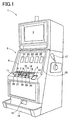
- Fig. 1 is a perspective view of the slot machine.
- the slot machine 1 has a cabinet 2 constructing a whole of the slot machine 1.
- an upper liquid crystal display 3 is arranged, and at a front central part of the cabinet 2 a lower liquid crystal display 4 is arranged.
- the upper liquid crystal display 3 is constructed from a liquid crystal display device which is generally used, and the lower liquid crystal display 4 is constructed from, so-called, a transparent liquid crystal display device.
- game operation method kinds of winning combinations and payout therefor and information concerning with the game such as various effects thereof are displayed.
- the lower liquid crystal display 4 as shown in Fig.
- variable display portions 21, 22, 23, 24, and 25 are basically displayed and various symbols (mentioned later) are scrolled to the downward direction from the upward direction while being variably displayed on each of the variable display portions 21 to 25.
- various symbols described hereinafter.
- the change button 6 is pressed when exchanging the bill inserted in the bill insertion portion 10, and the exchanged coins are paid out through a coin payout chute 15 to a coin tray 16 which is formed at the lower part of the cabinet 2.
- a change switch 62 (explained hereinafter) is attached, and a switch signal is output to a CPU 50 from the change switch 62 based on press of the change button 6.
- the payout button 7 is usually pressed when games are terminated, and when the payout button 7 is pressed coins got in games are paid out through the coin payout chute 15 to the coin tray 16.
- a payout (cashout) switch 63 (mentioned hereinafter) is attached and a switch signal is output to the CPU 50 from the payout switch 63 based on press of the payout button 7.
- the help button 8 is pressed when the player cannot understand game operation method, and when the help button 8 is pressed, various help information is displayed on the upper liquid crystal display 3 or the lower liquid crystal display 4.
- a help switch 64 (mentioned hereinafter) is attached and a switch signal is output to the CPU 50 from the help switch 64 based on press of the help button 8.
- a coin sensor 65 (mentioned hereinafter) is positioned, and when the coin is inserted in the coin insertion slot 9 a coin detection signal is output to the CPU 50 through the coin sensor 65.
- a bill sensor 66 (mentioned hereinafter) is positioned, and when the bill is inserted in the bill insertion portion 10 a bill detection signal is output to the CPU 50 through the bill sensor 66.
- the 1-BET button 11 every the 1-BET button is pressed one credit is betted, and to the 1-BET button 11, a 1-BET switch 59 is attached and when the 1-BET button 11 is pressed a switch signal is output to the CPU 50 from the 1-BET switch 59 based on press of the 1-BET button 11.
- the SPIN/REPEAT BET button 12 is the button to start games from the present bet number or the previous bet number by press thereof, thereby variable display of the symbols is started on the variable display portions 21 to 25 of the lower liquid crystal display 4.
- Tb the SPIN/REPEAT BET button 12, a spin switch 58 (mentioned later) is attached, and when the SPIN/REPEAT BET button 12 is pressed a switch signal is output to the CPU 50 from the spin switch 58 based on press of the SPIN/REPEAT BET button 12.
- the bet number which can be betted by press of the SPIN/REPEAT BET button 12 there may exist 1, 2, 3 and 5 bets.
- the 3-BET button 13 is the button to start games from 3 bets on the basis of press thereof.
- a 3-BET switch 60 (mentioned hereinafter) is attached and when the 3-BET button 13 is pressed a switch signal is output to the CPU 50 from the 3-BET switch 60.
- the 5-BET button 14 is the button to start games from 5 bets on the basis of press thereof.
- a 5-BET switch 61 is attached and when the 5-BET button is pressed a switch signal is output to the CPU 50 from the 5-BET switch 61 on the basis of press thereof.
- the coin payout chute 15 is formed and the coin tray 16 to receive coins paid out from the coin payout chute 15 is provided.
- a coin detection part 73 constructed from a sensor and the like is positioned and the coin detection part 73 detects the number of coins paid out from the coin payout chute 15.
- stop buttons 26 to 30 are provided corresponding to each of the variable display portions 21 to 25, respectively.
- stop buttons are pressed when the symbols, which are scrolled on the variable display portions, are stopped and displayed thereon, the symbols cannot be stopped at timing of the press operation of the stop buttons 26 to 30.
- the switch signal output from the stop button switch 67 based on press of each of the stop buttons 26 to 30 is utilized to the end only as a trigger when the symbols scrolled on the variable display portions are stopped and displayed.
- a start lever 17 is arranged rotatably within a predetermined angle range.
- a start switch 57 (mentioned hereinafter) is attached and when the start lever 17 is rotated a switch signal occurring from the start switch 57 is output to the CPU 50.
- Fig. 2 is an exploded perspective view of the lower liquid crystal display 4.
- the lower liquid crystal display 4 is construed by arranging from the front side of the slot machine 1; the reel glass base 31, the bezel metal frame 32, the transparent liquid crystal panel 33, the liquid crystal holder 34, the diffusion sheet 35, the light guiding plate 36, the white reflector 37, the rear holder 38 and the antistatic sheet 39.
- the diffusion sheet 35 three openings 35A, 35B, 35C, 35D, 35E are formed.
- the openings 35A ⁇ 38A construct the variable display portion 21 (see Fig. 1) by superimposing so as to coincide with each other.
- the openings 35B ⁇ 38B construct the variable display portion 22 (see Fig. 1) by superimposing so as to coincide with each other and the openings 35C ⁇ 38C construct the variable display portion 23 (see Fig.
- variable display portion 24 by superimposing so as to coincide with each other.
- openings 35D ⁇ 38D construct the variable display portion 24 (see Fig. 1) by superimposing so as to coincide with each other and the openings 35E ⁇ 38E construct the variable display portion 25 (see Fig. 1) by superimposing so as to coincide with each other.
- the openings 35A ⁇ 35E of the diffusion sheet 35 and the openings 36A ⁇ 36E of the light guiding plate 36 construct the light transmitting areas to retain visibility of the variable display portions 21 to 25.
- a pair of cathode ray tubes (not shown) are arranged as light source of the liquid crystal panel 33. And at an upper and lower positions in the rear side of each of openings 38A ⁇ 38D in the holder 38, a pair of cold cathode ray tubes (not shown) may be arranged.
- the liquid crystal panel 33 is a transparent electric display panel on which transparent electrodes such as Ito are formed, and the circumference in rear side of the display portion of the liquid crystal panel 33 is held by the liquid crystal holder 34.
- the light guiding plate 36 is made of the light transmitting resin panel, and in the light guiding plate 36 lens cut portions are formed, the lens cut portions guiding light emitted from the cold cathode ray tubes (not shown) positioned at side positions to the rear side of the liquid crystal panel 33.
- the light diffusion sheet 35 is made from a light transmitting resin sheet and diffuses light led thereto by the light guiding plate 36 and levels light irradiated to the liquid crystal panel 33.
- the liquid crystal holder 34 for holding the liquid crystal panel 33, the diffusion sheet 35 and the light guiding plate 36 are assembled into one-piece construction and circumference thereof is inserted in the bezel metal frame 32. Thereby, the front side of the display portion in the liquid crystal panel 33 is retained by the bezel metal frame 32.
- Circumferences of the liquid crystal holder 34, the light diffusion sheet 35 and the light guiding plate 36, which are inserted in the bezel metal frame 32 and assembled into one-piece construction, is further inserted in the reel glass base 31 and retained by the reel glass base 31 in a state that the front display plane of the liquid crystal panel 33 is opened.
- the rear holder 38 is made from a white resin plate and retains to the reel glass base 31 the bezel metal frame 32 supported to the reel glass base 31, the liquid crystal holder 34 holding the liquid crystal panel 33, the light diffusion sheet 35 and the light guiding plate 36 from the rear sides thereof.
- the rear holder 38 also functions as a reflecting plate for reflecting light emitted from the cold cathode ray tubes to the light guiding plate 36 toward the liquid crystal panel 33.
- the antistatic sheet 39 is made transparent and adhered to the rear plane of the rear holder 38 by double-sided adhesive tape, thereby the antistatic sheet 39 covers the rear plane of each of the openings 38A - 38E formed in the rear holder 38.
- FIG. 3 is an explanatory view showing symbol rows utilized in the base game, and the symbol row 41 is the symbol row which is variably displayed on the variable display portion 21, the symbol row 42 is the symbol row which is variably displayed on the variable display portion 22, the symbol row 43 is the symbol row which is variably displayed on the variable display portion 23, the symbol row 44 is the symbol row which is variably displayed on the variable display portion 24 and the symbol row 45 is the symbol row which is variably displayed on the variable display portion 25.
- the symbol rows 41, 42, 44 and 45 commonly have the same arrangement of the symbols and such arrangement of the symbols is constructed from eleven symbols in which the triple BAR 91, the cherry 92, the symbol seven 94, the single BAR 95 and the blank (no symbol exists) 96 are voluntarily combined.
- one joker 97 is further arranged in the symbol row 43.
- This joker 97 functions as a symbol to shift to the free game in the base game, and when the joker 97 is stopped and displayed on the pay line (mentioned later) in the variable display portion 23, the game condition shifts to the free game from the base game. And in the free game, the joker 97 functions as a symbol according to which the payout becomes twice.
- Fig. 4 is a block diagram schematically showing the control system in the slot machine 1.
- the control system of the slot machine 1 is basically constructed from the CPU 50, and a ROM 51 and a RAM 52 are connected to the CPU 50.
- the ROM 51 stores main process program mentioned later, various effect programs for executing various effects on the upper liquid crystal display 3 and the lower liquid crystal display 4 according to progress in games, a lottery table utilized in lottery of the winning combination in the base game, a lottery table utilized in lottery of contents of free games, a lottery table utilized in lottery of the winning combination corresponding to free games, various programs necessary for controlling the slot machine 1 and various data tables and the like.
- the RAM 52 is a memory for temporarily storing various data calculated by the CPU 50.
- a clock pulse generator 53 for generating standard clock pulses and a frequency divider 54 are connected, and a random number generator 55 and a sampling circuit 56 are also connected. Random number sampled by the random number generator 56 is utilized in various lotteries of the winning combinations, the effects and the like.
- the start switch 57 attached to the start lever 17, the spin switch 58 attached to the SPIN/REPEAT BET button 12, the 1-BET switch 59 attached to the 1-BET button 11, the 3-BET switch 60 attached to the 3-BET button 13, the 5-BET switch 61 attached to the 5-BET button 14, the change switch 62 attached to the change button 6, the payout switch 63 attached to the payout button 7 and the help switch 64 attached to the help button 8 are connected respectively.
- the CPU 50 controls the slot machine 1 to execute various operations corresponding to each button, based on the switch signal output from each switch when such buttons arc pressed.
- the coin sensor 65 positioned in the coin insertion slot 9 and the bill sensor 66 positioned in the bill insertion portion 10 are connected respectively.
- the coin sensor 65 detects coins inserted from the coin insertion slot 9 and the CPU 50 calculates the number of inserted coins based on the coin detection signal output from the coin sensor 65.
- the bill sensor 66 detects the kind and sum of bill and the CPU 50 calculates the number of coins equivalent to sum of bill, based on the bill detection signal output from the bill sensor 66.
- the stop button switches 67 attached to the stop buttons 26 to 30 are connected. When press operation of the stop buttons 26 to 30 is conducted, switch signals are output from the stop button switches 67 and the CPU 50 stops and displays the symbols which are scrolled on the variable display portions 21 to 25, based on switch signals.
- a hopper 71 is connected to the CPU 50, a hopper 71 is connected through a hopper drive circuit 70.
- a drive signal is output to the hopper circuit 70 from the CPU 50, the hopper 71 pays out predetermined number of coins from the coin payout chute 15
- a coin detection part 73 is connected through a payout completion signal circuit 72.
- the coin detection part 73 is arranged in the coin payout chute 15 and when the coin detection part 73 detects that a predetermined number of coins are paid out from the coin payout chute 15, the payout completion signal is output to the payout completion signal circuit 72 from the coin detection part 73. Based on this, the payout completion signal circuit 72 outputs the payout completion signal to the CPU 50.
- the upper liquid crystal display 3 is connected through a liquid crystal drive circuit 74 and the lower liquid crystal display 4 is connected through a liquid crystal drive circuit 75.
- the liquid crystal drive circuit 74 is constructed from a program ROM 81, an image ROM 82, an image control CPU 83, a work RAM 84, a VDP (Video Display Processor) 85 and a video RAM 86.
- the program ROM 81 an image control program concerning with display on the lower liquid crystal display 4 and various selection tables are stored.
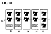
- the image ROM 82 for example, it is stored dot data for forming images such as the symbol rows 41 ⁇ 45 in Fig. 3 displayed on the lower liquid crystal display 4 (or variable display portions 21 to 25) and the symbol rows 41 ⁇ 45 shown in Figs. 11 and 13.
- the image control CPU 83 determines images displayed on the lower liquid crystal display 4 among the dot data stored in the image ROM 82 beforehand, according to the image control program stored in the program ROM 81 based on parameters set by the CPU 50.
- the work RAM 84 functions as the temporary memory when the above image control program is executed by the image control CPU 83.
- the VDP 85 forms images corresponding to display contents determined by the image control CPU 83 and outputs the images to the lower liquid crystal display 4. Thereby, for example, the symbol rows 41 ⁇ 45 of Fig. 3 and the symbol rows 41 ⁇ 45 of Figs. 11 and 13 are scrolled and displayed on the lower liquid crystal display 4 (or variable display portions 21 to 25).
- the video RAM 86 functions as the temporary memory when images are formed by the VDP 85.
- LEDs 78 are connected through a LED drive circuit 77.
- a plurality of LEDs 78 are arranged on the front plane of the slot machine 1 and the LEDs 78 are controlled so as to turn on based on the drive signals from the CPU 50.
- a speaker 80 and a sound output circuit 79 are connected to the CPU 50 and the speaker 80 produces various effective sounds when various effects are conducted based on the output signal from the sound output circuit 79.
- Fig. 6 is an explanatory view showing the lottery table of the winning combination utilized in the base games.
- a range of random number values utilized in the lottery table of the winning combination lie within 0 ⁇ 16383.
- a range 1 of random number values will be explained. That is to say, in a case that the random number value sampled by the random number sampling circuit 56 lies in a range of 0 ⁇ 3, the free game is triggered. In this case, the joker 97 is stopped and displayed on the pay line in the variable display portion 23 and the game condition can be shifted to the free game.
- the free game is a game conducted after the base game is done and is generally beneficial for the player in many cases. For example, when the game condition shifts to the free game, games are continuously done during 10 games, 20 games or 30 games, corresponding rank of the free game. At that time, in the free game, winning probability for winning various winning combinations is generally set high, therefore the player can get a lot of coins in many cases.
- two kinds of free games such as the first free game and the second free game are set beforehand.
- the winning combination of the seven (7) is won.
- the symbol seven 94 is stopped and displayed on the pay line in each of the variable display portions 21 to 25.
- the winning combination of the triple BAR is won.
- the triple BAR 91 is stopped and displayed on the pay line in each of the variable display portions 21 to 25.
- the random number value sampled lies in a range of 32 ⁇ 255, the winning combination of the single BAR is won.
- the single BAR 95 is stopped and displayed on the pay line in each of the variable display portions 21 to 25.
- the random number value sampled lies in a range of 256 ⁇ 511, the winning combination of the cherry is won.
- the cherry 92 is stopped and displayed on the play line in each of the variable display portions 21 to 25.
- a range 2 of random number values will be explained. That is to say, in a case that the random number value sampled by the random number sampling circuit 56 lies in a range of 0 ⁇ 6, the free game is triggered. In this case, the joker 97 is stopped and displayed on the pay line in the variable display portion 23 and the game condition can be shifted to the free game.
- the winning combination of the seven (7) is won.
- the symbol seven 94 is stopped and displayed on the pay line in each of the variable display portions 21 to 25.
- the random number value sampled lies in a range of 56 ⁇ 265
- the winning combination of the triple BAR is won.
- the triple BAR 91 is stopped and displayed on the pay line in each of the variable display portions 21 to 25.
- the random number value sampled lies in a range of 266 ⁇ 613
- the single BAR 95 is stopped and displayed on the pay line in each of the variable display portions 21 to 25. And if the random number value sampled lies in a range of 614 ⁇ 1023, the winning combination of the cherry is won. In this case, the cherry 92 is stopped and displayed on the play line in each of the variable display portions 21 to 25.
- the random number value lies in a range of 1024 ⁇ 16383, it leads to loss of winning combination (no winning combination can be won).
- symbol combination other than the winning combination is stopped and displayed on the pay line in each of variable display portions 21 to 25. Comparing the range 1 with the range 2, the range that loss of winning combination occurs is wider in the range 1 than in the range 2.
- Fig. 16 is an explanatory view showing the pay line. Here, only the center pay line L2 is made active.
- Fig. 7 is an explanatory view showing the lottery table of the free game.
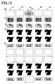
- Fig. 12 is an explanatory view showing the symbol rows which arc utilized in the first free game and displayed on each of the variable display portions 21 to 25.
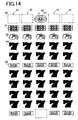
- Fig. 14 is an explanatory view showing the symbol rows which are utilized in the second free game and displayed on each of variable display portions 21 to 25.
- the game condition can be shifted to the free game after the base game is finished.
- the free game the first game and the second free game are provided beforehand.
- the random number values utilized in the lottery table of the free game lie within 0 ⁇ 15. And in a case that the random number value sampled by the random number sampling circuit 56 lies in a range of 0 ⁇ 12, the game condition is shifted to the first free game after the base game is finished. Further, when the first free game is conducted, the symbol rows 41, 42, 43, 44 and 45 shown in Fig. 12 are utilized. Here, comparing the symbol rows in the first free game with the symbol rows in the base game shown in Fig. 3, two blanks (area that no symbol exists) 96 are changed to the symbol sevens 94 respectively in the symbol rows 41, 42, 43, 44 and 45 in Fig. 12, as a result, two symbol sevens 94 are increased.
- the game condition is shifted to the second free game after the base game is finished.
- the symbol rows 41, 42, 43, 44 and 45 shown in Fig. 14 are utilized.
- four blanks (area that no symbol exists) 96 are changed to the symbol sevens 94 respectively in the symbol rows 41, 42, 43, 44 and 45 in Fig. 14, as a result, four symbol sevens 94 are increased.
- Fig. 8 is an explanatory view showing the lottery table of the winning combination utilized when the first free game is done.
- a range of random number values utilized in the lottery table of the winning combination lie within 0 ⁇ 16383.
- the random number value sampled by the random number sampling circuit 56 lies in a range of 0 ⁇ 3
- the joker is won.
- the joker 97 is stopped and displayed on the pay line in the variable display portion 23 and the payout becomes twice.
- the winning combination of the seven (7) is won.
- the symbol seven 94 is stopped and displayed on the pay line in each of the variable display portions 21 to 25, and the payout becomes 100.
- the random number value sampled lies in a range of 1257 ⁇ 1272
- the winning combination of the triple BAR is won.
- the triple BAR 91 is stopped and displayed on the pay line in each of the variable display portions 21 to 25, and the payout becomes 40.
- the random number value sampled lies in a range of 1273 ⁇ 1486, the winning combination of the single BAR is won.
- the single BAR 95 is stopped and displayed on the pay line in each of the variable display portions 21 to 25, and the payout becomes 10.
- the random number value sampled lies in a range of 1487 ⁇ 1742, the winning combination of the cherry is won.
- the cherry 92 is stopped and displayed on the play line in each of the variable display portions 21 to 25, and the payout becomes 5.
- the random number value lies in a range of 1743 ⁇ 16383, it leads to loss of winning combination (any winning combination cannot be won).
- symbol combination other than the winning combination is stopped and displayed on the pay line in each of variable display portions 21 to 25. And the payout cannot be obtained.
- the winning probability for the winning combination in the first free game is set high.
- the winning probability to win the winning combination of the seven (7) is set higher. This is based on that two symbol sevens 94 are increased in the symbol rows 41, 42, 43,44, and 45, as mentioned.
- Fig. 9 is an explanatory view showing the lottery table of the winning combination utilized when the second free game is done.
- a range of random number values utilized in the lottery table of the winning combination lie within 0 ⁇ 16383.
- the random number value sampled by the random number sampling circuit 56 lies in a range of 0 ⁇ 3
- the joker is won.
- the joker 97 is stopped and displayed on the pay line in the variable display portion 23 and the game condition is again shifted to the second free game.
- the winning combination of the seven (7) is won.
- the symbol seven 94 is stopped and displayed on the pay line in each of the variable display portions 21 to 25.
- the random number value sampled lies in a range of 4829 ⁇ 4844
- the winning combination of the triple BAR is won.
- the triple BAR 91 is stopped and displayed on the pay line in each of the variable display portions 21 to 25.
- the random number value sampled lies in a range of 4845 ⁇ 5068
- the single BAR 95 is stopped and displayed on the pay line in each of the variable display portions 21 to 25. And if the random number value sampled lies in a range of 5069 ⁇ 5323, the winning combination of the cherry is won. In this case, the cherry 92 is stopped and displayed on the play line in each of the variable display portions 21 to 25.
- payouts in the second free game are as same as those shown in the lottery table of the winning combination which is utilized when the lottery of the winning combination in the first free game in Fig. 7 is done.
- the winning probability for the winning combination in the second free game is set high.
- the winning probability to win the winning combination of the seven (7) is set higher. This is based on that four symbol sevens 94 arc increased in the symbol rows 41, 42, 43, 44, and 45, as mentioned.
- Fig. 10 is a flowchart of the main process program.
- S start acceptance process
- This start acceptance process is process to receive the switch signal output from the start switch 57, the spin switch 58, the 1-BET switch 59, the 3-BET switch 60 or the 5-BET switch 61, based on operation of the start lever 17, the SPIN/REPEAT BET button 12, the 1-BET button 11, the 3-BET button 13 or the 5-BET button 14.
- the base game is started.
- the lottery of the winning combination in the base game is done by utilizing the lottery table of the winning combination (random number value range 1) of Fig. 6 in the base game.
- the lottery of the first free game or the second free game is conducted by using the lottery table of the free game in Fig. 7. Further, the number of times that the free games are continuously executed is determined among 10 games, 20 games and 30 games.
- the symbols (symbols in each of the symbol rows 41 to 45 shown in Fig. 3) are scrolled on the variable display portions 21 to 25, based on the switch signal, which is received In S1, output from the start switch 57, the spin switch 58, the 1-BET switch 59, the 3-BET switch 60 or the 5-BET switch 61. And if the stop buttons 26 to 30 corresponding to the variable display portions 21 to 25 on which the symbols are scrolled are pressed, scrolling of each of the symbols on the variable display portions 21 to 25 is stopped by using the switch signal output from the pressed stop button as the trigger.
- each of the stop buttons 26 to 30 has no relation with so-called "observation push” which is done for purpose to allow technical intervention by the player.
- the switch signal output from each of the stop buttons 26 to 30 is used to the end only as the trigger when the symbols scrolled on the variable display portions 21 to 25 are stopped and displayed thereon. Therefore, the symbols on each of the variable display portions 21 to 25 are stopped and displayed thereon based on only the lottery result obtained in S2.
- the specific condition corresponds to that the free game is triggered in the lottery process of S2. At that time, if it is determined that the specific condition is not realized (S5: NO), the main process is finished. On the other hand, if it is determined that the specific condition is realized (S5: YES), the procedure shifts to S6. In S6, scrolling of the symbols on the variable display portions 21 to 25 is automatically started and the free game is started. At that time, if the first free game is triggered in S2, the symbol rows 41 to 45 shown in Fig. 12 are utilized as the symbols scrolled on the variable display portions 21 to 25.
- the symbol rows 41 to 45 shown in Fig. 14 are utilized as the symbols scrolled on the variable display portions 21 to 25. Thereafter, in order to stop of scrolling of the symbols on the variable display portions 21 to 25, it is called player's attention so that the player presses the stop buttons 26 to 30 by the words (for example, "switch on") displayed on the lower liquid crystal display 4 or blinking of the stop buttons 26 to 30.
- S7 various lottery processes are conducted at the timing that the procedure shifts to S7. Concretely, if the first free game is already triggered, the lottery of the winning combination in the first free game is done by using the lottery table of the winning combination in the first free game shown in Fig. 8. On the other hand, if the second free game is already triggered, the lottery of the winning combination in the second free game is done by using the lottery table of the winning combination in the second free game shown in Fig. 9.
- each of the stop buttons 26 to 30 has no relation with so-called "observation push” which is done for purpose to allow technical intervention by the player.
- the switch signal output from each of the stop buttons 26 to 30 is used to the end only as the trigger when the symbols scrolled on the variable display portions 21 to 25 are stopped and displayed thereon. Therefore, the symbols on each of the variable display portions 21 to 25 are stopped and displayed thereon based on only the lottery result obtained in S7.
- the lottery of the first free game or the second free game is conducted (S2).
- the symbol rows 41 to 45 shown in Fig. 11 are utilized (S6) as the symbols scrolled on the variable display portions 21 to 25 and the lottery of the winning combination in the first free game is done (S7) by utilizing the lottery table of the winning combination in the first free game shown in Fig. 8.
- the lottery table of the winning combination in the first free game of Fig. 8 and the lottery table of the winning combination in the second free game of Fig. 9 are provided. Therefore, even if the number of the symbol seven 94 is changed (reduced), game process can be rapidly done by conducting a simple table control.
- the stop buttons 26 to 30 producing the trigger for stopping and displaying the symbols scrolled on the variable display portions 21 to 25, and although the symbols are not stopped on the variable display portions 21 to 25 at the timing that the stop buttons 26 to 30 are pressed, it can be given to the player an impression that the symbol combination corresponding to the winning combination may be stopped and displayed under a beneficial state for the player that two or four of the symbol sevens 94 scrolled on the variable display portions 21 to 25 are increased.
- the lottery of the winning combination in the first free game is done by using the lottery table of the winning combination shown in Fig. 8 and if the second free game is triggered, the lottery of the winning combination in the second free game is done by using the lottery table of the winning combination shown in Fig. 9 (S7).
- the symbols are scrolled, stopped and displayed on the variable display portions 21 to 25 according to the lottery result by using stop instruction occurring when the player presses the stop buttons 26 to 30 as the trigger.
- stop instruction occurring when the player presses the stop buttons 26 to 30 as the trigger.
- the second embodiment has basically the same construction as that in the first embodiment.
- characteristic construction in the second embodiment will be mainly described hereinafter.
- Fig. 20 is an explanatory view showing the pay line. Here, only the center pay line L2 is made active.
- Fig. 7 is an explanatory view showing the lottery table of the free game.
- Fig. 17 is an explanatory view showing the example of the symbols which are utilized in the first free game and displayed on each of the variable display portions 21 to 25.
- Fig. 18 is an explanatory view showing the examples of the symbols and the symbol rows which are utilized in the second free game and displayed on each of the variable display portions 21 to 25.
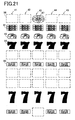
- Fig. 21 is an explanatory view schematically showing the symbol rows which are utilized in the first free game and displayed on each of variable display portions 21 to 25.
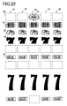
- Fig. 22 is an explanatory view schematically showing the symbol rows which are utilized in the second free game and displayed on each of variable display portions 21 to 25.
- the game condition can be shifted to the free game after the base game is finished.
- the free game the first game and the second free game are provided beforehand.
- the random number values utilized in the lottery table of the free game lie within 0 ⁇ 15. And in a case that the random number value sampled by the random number sampling circuit 56 lies in a range of 0 ⁇ 12, the game condition is shifted to the first free game after the base game is finished. Further, when the first free game is conducted, the symbol rows 41, 42, 43, 44 and 45 shown in Fig. 21 are utilized. Here, comparing the symbol rows 41 to 45 shown in Fig. 21 with the symbol rows in the base game shown in Fig. 3, one symbol seven 94 is enlarged twice in the vertical direction by utilizing one blank (area that no symbol exists) 96.
- the game condition is shifted to the second free game after the base game is finished.
- the symbol rows 41, 42, 43, 44 and 45 shown in Fig. 22 are utilized.
- one symbol seven 94 is enlarged three times in the vertical direction by utilizing two blanks (area that no symbol exists) 96. Therefore, when the symbol seven 94 is stopped and displayed on the variable display portions 21 to 25, there will be a case that the symbol seven 94, which is enlarged three times in the vertical direction, is stopped and displayed, for example as shown in Fig. 18.
- two blanks (area that no symbol exists) 96 are substantially changed to the symbol seven 94, thus it concludes that two symbol sevens 94 are increased.
- Fig. 8 is an explanatory view showing the lottery table of the winning combination utilized when the first free game is done.
- a range of random number values utilized in the lottery table of the winning combination lie within 0 ⁇ 16383.
- the random number value sampled by the random number sampling circuit 56 lies in a range of 0 ⁇ 3
- the joker is won.
- the joker 97 is stopped and displayed on the pay line in the variable display portion 23 and the payout becomes twice.
- the winning combination of the seven (7) is won.
- the symbol seven 94 including the symbol seven 94 enlarged twice in the vertical direction is stopped and displayed on the pay line in each of the variable display portions 21 to 25, and the payout becomes 100.
- the winning combination of the triple BAR is won.
- the triple BAR 91 is stopped and displayed on the pay line in each of the variable display portions 21 to 25, and the payout becomes 40.
- the random number value sampled lies in a range of 1273 ⁇ 1486, the winning combination of the single BAR is won.
- the single BAR 95 is stopped and displayed on the pay line in each of the variable display portions 21 to 25, and the payout becomes 10.
- the random number value sampled lies in a range of 1487 ⁇ 1742, the winning combination of the cherry is won.
- the cherry 92 is stopped and displayed on the play line in each of the variable display portions 21 to 25, and the payout becomes 5.
- the random number value lies in a range of 1743 ⁇ 16383, it leads to loss of winning combination (any winning combination cannot be won).
- symbol combination other than the winning combination is stopped and displayed on the pay line in each of variable display portions 21 to 25. And the payout cannot be obtained.
- one symbol seven 94 is enlarged twice in the vertical direction by using one blank (area that no symbol exists) 96 in the symbol rows 41 to 45 shown in Fig. 21, in comparison with the symbol rows utilized in the base game as shown in Fig. 3.
- the player can get a lot of coins in many cases.
- Fig. 9 is an explanatory view showing the lottery table of the winning combination utilized when the second free game is done.
- a range of random number values utilized in the lottery table of the winning combination lie within 0 ⁇ 16383.
- the random number value sampled by the random number sampling circuit 56 lies in a range of 0 ⁇ 3
- the joker is won.
- the joker 97 is stopped and displayed on the pay line in the variable display portion 23 and the game condition is again shifted to the second free game.
- the winning combination of the seven (7) is won.
- the symbol seven 94 including the symbol seven 94 enlarged three times in the vertical direction is stopped and displayed on the pay line in each of the variable display portions 21 to 25.
- the random number value sampled lies in a range of 4829 ⁇ 4844
- the winning combination of the triple BAR is won.
- the triple BAR 91 is stopped and displayed on the pay line in each of the variable display portions 21 to 25.
- the random number value sampled lies in a range of 4845 ⁇ 5068, the winning combination of the single BAR is won.
- the single BAR 95 is stopped and displayed on the pay line in each of the variable display portions 21 to 25. And if the random number value sampled lies in a range of 5069 ⁇ 5323, the winning combination of the cherry is won. In this case, the cherry 92 is stopped and displayed on the play line in each of the variable display portions 21 to 25.
- payouts in the second free game are as same as those shown in the lottery table of the winning combination which is utilized when the lottery of the winning combination in the first free game in Fig. 8 is done.
- the winning probability for the winning combination in the second free game is set high.
- the winning probability to win the winning combination of the seven (7) is set higher. This is based on that two symbol sevens 94 are substantially increased in the symbol rows 41, 42, 43,44, and 45, as mentioned. The reason is as follows. Although the symbol rows 41 to 45 shown in Fig.
- Fig. 10 is a flowchart of the main process program.
- S start acceptance process
- This start acceptance process is process to receive the switch signal output from the start switch 57, the Spin switch 58, the 1-BET switch 59, the 3-BET switch 60 or the 5-BET switch 61, based on operation of the start lever 17, the SPIN/REPEAT BET button 12, the 1-BET button 11, the 3-BET button 13 or the 5-BET button 14.
- the base game is started.
- the lottery of the winning combination in the base game is done by utilizing the lottery table of the winning combination (random number value range 1) of Fig. 6 in the base game.
- the lottery of the first free game or the second free game is conducted by using the lottery table of the free game in Fig. 7. Further, the number of times that the free games are continuously executed is determined among 10 games, 20 games and 30 games.
- the symbols (symbols in each of the symbol rows 41 to 45 shown in Fig. 3) are scrolled on the variable display portions 21 to 25, based on the switch signal, which is received In S1, output from the start switch 57, the spin switch 68, the 1-BET switch 59, the 3-BET switch 60 or the 5-BET switch 61. And if the stop buttons 26 to 30 corresponding to the variable display portions 21 to 25 on which the symbols are scrolled are pressed, scrolling of each of the symbols on the variable display portions 21 to 25 is stopped by using the switch signal output from the pressed stop button as the trigger.
- each of the stop buttons 26 to 30 has no relation with so-called "observation push” which is done for purpose to allow technical intervention by the player.
- the switch signal output from each of the stop buttons 26 to 30 is used to the end only as the trigger when the symbols scrolled on the variable display portions 21 to 25 are stopped and displayed thereon. Therefore, the symbols on each of the variable display portions 21 to 25 are stopped and displayed thereon based on only the lottery result obtained in S2.
- the specific condition corresponds to that the free game is triggered in the lottery process of S2. At that time, if it is determined that the specific condition is not realized (S5: NO), the main process is finished. On the other hand, if it is determined that the specific condition is realized (S5: YES), the procedure shifts to S6. In S6, scrolling of the symbols on the variable display portions 21 to 25 is automatically started and the free game is started. At that time, if the first free game is triggered in S2, the symbol rows 41 to 45 shown in Fig. 21 are utilized as the symbols scrolled on the variable display portions 21 to 25.
- the symbol rows 41 to 45 shown in Fig. 22 are utilized as the symbols scrolled on the variable display portions 21 to 25. Thereafter, in order to stop of scrolling of the symbols on the variable display portions 21 to 25, it is called player's attention so that the player presses the stop buttons 26 to 30 by the words (for example, "switch on") displayed on the lower liquid crystal display 4 or blinking of the stop buttons 26 to 30.
- S7 various lottery processes are conducted at the timing that the procedure shifts to S7. Concretely, if the first free game is already triggered, the lottery of the winning combination in the first free game is done by using the lottery table of the winning combination in the first free game shown in Fig. 8. On the other hand, if the second free game is already triggered, the lottery of the winning combination in the second free game is done by using the lottery table of the winning combination in the second free game shown in Fig. 9.
- each of the stop buttons 26 to 30 has no relation with so-called "observation push” which is done for purpose to allow technical intervention by the player.
- the switch signal output from each of the stop buttons 26 to 30 is used to the end only as the trigger when the symbols scrolled on the variable display portions 21 to 25 are stopped and displayed thereon. Therefore, the symbols on each of the variable display portions 21 to 25 are stopped and displayed thereon based on only the lottery result obtained in S7.
- the lottery of the first free game or the second free game is conducted (S2).
- the lottery of the winning combination is done in the first free game by utilizing the lottery table of the winning combination shown in Fig. 8 (S7).
- the symbol rows 41 to 45 one of the symbol sevens 94 is enlarged twice in the vertical direction
- Fig. 21 are utilized as the symbols scrolled on the variable display portions 21 to 25, therefore one blank (area that no symbol exists) 96 is substantially changed to the symbol seven 94 and it concludes that one symbol seven 94 is increased in each of the variable display portions 21 to 25.
- the lottery of the winning combination is done in the second free game by utilizing the lottery table of the winning combination shown in Fig. 9 (S7).
- the symbol rows 41 to 45 one of the symbol sevens 94 is enlarged three times in the vertical direction
- two blanks (area that no symbol exists) 96 are substantially changed to the symbol sevens 94 and it concludes that two symbol sevens 94 arc increased in each of the variable display portions 21 to 25. Therefore, one or two of the symbol sevens 94, which are scrolled on the variable display portions 21 to 25, can be increased, thus the winning combination of the seven (7) can be easily won.
- the lottery table of the winning combination in the first free game of Fig. 8 and the lottery table of the winning combination in the second free game of Fig. 9 are provided. Therefore, even if the multiple of the symbol seven 94 is changed (increased), game process can be rapidly done by conducting a simple table control.
- the stop buttons 26 to 30 producing the trigger for stopping and displaying the symbols scrolled on the variable display portions 21 to 25, and although the symbols are not stopped on the variable display portions 21 to 25 at the timing that the stop buttons 26 to 30 are pressed, it can be given to the player an impression that the symbol combination corresponding to the winning combination may be stopped and displayed under a beneficial state for the player that one or two of the symbol seven (s) 94 is/are substantially increased in each of the variable display portions 21 to 25 by using in the first free game or the second free game the symbol rows 41 to 45 (Fig. 21 or Fig. 22) in each of which one of the symbol seven 94 is enlarged twice or three times in the vertical direction.
- the lottery of the winning combination in the first free game is done by using the lottery table of the winning combination shown in Fig. 8 and if the second free game is triggered, the lottery of the winning combination in the second free game is done by using the lottery table of the winning combination shown in Fig. 9 (S7).
- the symbols are scrolled, stopped and displayed on the variable display portions 21 to 25 according to the lottery result by using stop instruction occurring when the player presses the stop buttons 26 to 30 as the trigger.
- stop instruction occurring when the player presses the stop buttons 26 to 30 as the trigger.
- the lottery table in Fig. 7 is treated as the lottery table for changing the number of the symbols scrolled on the variable display portions 21 to 25 and the random number value is sampled by the random number sampling circuit 56 based on the switch signal output from the start switch 57, the spin switch 58, the 1-BET switch 59, the 3-BET switch 60 or the 5-BET switch 61, which are confirmed in S1 in Fig. 10. Further, based on the above sampled random number value the number of the utilized symbols scrolled on the variable display portions 21 to 25 may be determined. For example, among the range of the random number value within 0 ⁇ 15 in the lottery table shown in Fig.
- one blank (area that no symbol exists) 96 may be changed to the symbol seven 94 among the symbols scrolled on each of the variable display portions 21 to 25, and if the sampled random number value lies in the range of 13 ⁇ 15, three blanks 96 may be changed to the symbol sevens 94 among the symbols scrolled on each of the variable display portions 21 to 25.
- the random number value may be obtained every one of the variable display portions 21 to 25 and the blank 95 may be changed to the symbol seven every variable display portion.
- the blank 96 in addition to the first free game and the second free game, the blank 96 can be changed to the symbol seven 94 even in the base game among the symbols scrolled on the variable display portions 21 to 25.
- the slot machine 1 may be constructed as follows. That is, it is arranged an insertion button, which can insert coins to change the number of utilized symbols scrolled on the variable display portions 21 to 25 from the credit (stored coin number) stored in the slot machine 1, and the number of utilized symbols are changed according to operation number of the insertion button. In this case, in change process to change the number of utilized symbols, the operation number is counted in S1 of Fig. 10 and the number of utilized symbols is changed according to the counted operation number.
- coin number necessary for changing two blanks 96 to the symbol sevens 94 can be, for example, set to 100.
- coin number necessary for changing four blanks 96 to the symbol sevens 94 can be, for example, set to 300.
- the lottery of the winning combination in the base game is done by using the winning combination lottery table (range 1 of random number values) which is used in the base game shown in Fig. 6 in the lottery process of S2. Further in S3, the symbol rows 41 to 45 shown in Fig. 12 are utilized as the symbols scrolled on each of the variable display portions 21 to 25.
- the lottery of the winning combination in the base game is done by using the winning combination lottery table (range 2 of random number values) which is used in the base game shown in Fig. 6 in the lottery process of S2. Further in S3, the symbol rows 41 to 45 shown in Fig. 14 are utilized as the symbols scrolled on each of the variable display portions 21 to 25. According to this, in addition to the first free game and the second free game, the blank 96 can be changed to the symbol seven 94 even in the base game among the symbols scrolled on the variable display portions 21 to 25.
- the above situation may be similarly obtained if the number that the blank 96 is changed to the symbol seven 94 among the symbols scrolled on the variable display portions 21 to 25 is controlled corresponding to bet number by operation of the start lever 17, the SPIN/REPEAT BET button 12, the 1-BET button 11, the 3-BET button 13 or the 5-BET button 14.
- the slot machine 1 of the first embodiment is constructed so that the blank 96 displayed on the lower liquid crystal display 4 is changed to the symbol seven 94 and the changed symbol seven 94 is scrolled
- the slot machine 1 is not limited to this construction.
- the slot machine 1 may be constructed as follows. For example, as in the conventional slot machine, five reels, on outer periphery of each of which the symbol row 41, 42, 43, 44, 45 is formed respectively, may be rotatably supported, and if the number of utilized symbols which are scrolled is changed, illumination means such as LED may be arranged in rear side of each reel and the symbol scrolled in each reel may be emphasized by illuminating through the illumination means.
- stop buttons 26 to 30 are arranged corresponding to each of the variable display portions 21 to 25 and the trigger signal is output by pressing the stop button corresponding to one of the variable display portions 21 to 25 on which the symbol is scrolled, the symbols may be automatically stopped on four variable display portions among the variable display portions 21 to 25 except for one variable display portion and only the switch signal output from the stop button corresponding to the remaining variable display portion may be accepted. And in a case that each of the stop buttons 26 to 30 is not pressed for a predetermined time, each of the variable display portions 21 to 25 may be automatically stopped and displayed as the predetermined time is elapsed.
- the pattern of the pay line may be changed corresponding to the number of the symbol seven 94 which is changed from the blank 96 among the symbols scrolled on the variable display portions 21 to 25.
- the pattern of the pay line may be changed corresponding to the number of the symbol seven 94 which is changed from the blank 96 among the symbols scrolled on the variable display portions 21 to 25.
- the slot machine 1 may have the top line L1, the bottom line L3, the cross down-cross up line L4 which is constructed by combining the cross down line and the cross up line and the cross up-cross down line L5 which is constructed by combining the cross up lien and the cross down line, and the pay line which is made active may be determined corresponding to the number of the symbol seven 94 which is changed from the blank 96 among the symbols scrolled on the variable display portions 21 to 25.
- the pay line which is made active may be determined corresponding to the number of the symbol seven 94 which is changed from the blank 96 among the symbols scrolled on the variable display portions 21 to 25.
- the winning combination seven (7) is realized based on that the symbol sevens 94 are stopped and displayed along the top line L1 and the center line L2, thus the winning combination seven (7) can be easily won if the top line L1 is made active in addition to the center line L2. Therefore, it can be given to the player expectation that the specific winning combination can be easily won, thus interest for games can be highly maintained.
- state of the winning combination and the pay line which is made active among the lines L1 to L5 can be changed corresponding to the number of the symbol seven 94 which is changed from the blank 96 among the symbols scrolled on the variable display portions 21 to 25, thereby variations of the game can be increased and variegated game can be done.
- the symbol stopped and displayed on the pay line may be determined every each of the variable display portions 21 to 25.
- code numbers 0 ⁇ 10 are allotted to the symbol rows 41 to 45 each of which corresponds to each of the variable display portions 21 to 25 shown in Figs. 3, 12 and 14, and the lottery table shown in Fig. 23 is provided. And five random number values are sampled so as to correspond to each of the variable display portions 21 to 25.
- the random number value corresponding to the variable display portion 21 is the code number 1
- the symbol to which the code number 1 is allotted is stopped and displayed on the pay line
- the random number value corresponding to the variable display portion 22 is the code number 2
- the symbol to which the code number 2 is allotted is stopped and displayed on the pay line.
- the random number value corresponding to the variable display portion 23 is the code number 3
- the symbol to which the code number 3 is allotted is stopped and displayed on the pay line
- the random number value corresponding to the variable display portion 24 is the code number 4
- the random number value corresponding to the variable display portion 25 is the code number 5
- the symbol to which the code number 5 is allotted is stopped and displayed on the pay line.
- the lottery table shown in Fig. 23 although the random number value is evenly allotted against each of the code numbers, the lottery table, in which the random number values are unevenly allotted against the code numbers as shown in Fig. 24, may be utilized in order that the joker 97 to shift to the free game is made difficult to be stopped and displayed on the pay line.
- any one of the triple BAR 91, the cherry 92 and the single BAR 95 except for the symbol seven 94 May be changed and the symbol to be changed may be any one of the triple BAR 91, the cherry 92, the symbol seven 94 and single BAR 95 except for the blank 96.
- the slot machine 1 based on that it is utilized the symbol rows 41 to 45 in each of which one of the symbol sevens 94 is enlarged twice or three times in the vertical direction (Fig. 21 or Fig. 22), it is automatically determined on the basis of the lottery result by the lottery table for the free game shown in Fig. 6 that one or two of the symbol seven (s) 94 is/are substantially increased.
- the slot machine 1 is not limited to the above and may be constructed as follows.
- the lottery table in Fig. 7 is treated as the lottery table for selecting one of the symbol rows 41 to 45 (Fig. 14 or Fig. 15) in which one of the symbol sevens 94 is enlarged twice or three times and selection of the symbol row May be determined according to the random number value sampled by the random number sampling circuit 56 based on the switch signal output from the start switch 57, the spin switch 58, the 1-BET switch 59, the 3-BET switch 60 or the 5-BET switch 61, which are confirmed in S1 in Fig. 10.
- the symbol rows 41 to 45 in which one of the symbol sevens 94 is enlarged twice in the vertical direction are selected and if the sampled random number value lies within the range of 13 ⁇ 15, the symbol rows 41 to 45 in which one of the symbol sevens 94 is enlarged three times in the vertical direction (Fig. 22) are selected.
- the random number value may be obtained every one of the variable display portions 21 to 25 and the symbol row in which one of the symbol sevens 94 is enlarged twice or three times in the vertical direction may be selected every variable display portion.
- one or two of the symbol sevens 94 can be substantially increased even in the base game.
- an insertion button which can insert coins from the credit (stored coin number) stored in the slot machine 1
- the slot machine 1 may be constructed so as to select one of the symbol rows 41 to 45 in which one of the symbol sevens 94 is enlarged twice or three times in the vertical direction corresponding to operation number of the insertion button.
- the operation number of the insertion button is counted in S1 of Fig.
- coin number necessary for selecting the symbol rows 41 to 45 in each of which one of the symbol sevens 94 is enlarged twice in the vertical direction can be, for example, set to 100.
- coin number necessary for selecting the symbol rows 41 to 45 in each of which one of the symbol sevens 94 is enlarged three times in the vertical direction can be, for example, set to 300.
- the winning combination lottery is done in the base game in the lottery process in S2 by using the winning combination lottery table (range 1 of random number values) in the base game shown in Fig. 6, and in S3, the symbols are scrolled, stopped and displayed on the variable display portions 21 to 25 by using the symbol rows 41 to 45 in each of which one of the symbol sevens 94 is enlarged twice in the vertical direction (Fig. 21).
- the winning combination lottery is done in the base game in the lottery process in S2 by using the winning combination lottery table (range 2 of random number values) in the base game shown in Fig. 6, and in S3, the symbols are scrolled, stopped and displayed on the variable display portions 21 to 25 by using the symbol rows 41 to 45 in each of which one of the symbol sevens 94 is enlarged three times in the vertical direction (Fig. 22).
- one of two of the symbol sevens 94 can be substantially increased by using the symbol rows 41 to 45 in each of which one of the symbol sevens 94 is enlarged twice or three times in the vertical direction (Fig. 21 or Fig. 22) even in the base game.
- the above situation may be similarly obtained if the symbol rows 41 to 45 in each of which one of the symbol sevens 94 is enlarged twice or three times in the vertical direction (Fig. 21 or Fig. 22) are elected corresponding to bet number by operation of the start lever 17, the SPIN/REPEAT BET button 12, the 1-BET button 11, the 3-BET button 13 or the 5-BET button 14.
- the slot machine 1 of the second embodiment in order to substantially increase one or two of the symbol sevens 94, although the slot machine 1 of the second embodiment is constructed so that the symbol rows 41 to 45 in each of which one of the symbol sevens 94 is enlarged twice or three times in the vertical direction (Fig. 21 or Fig. 22), the slot machine 1 is not limited to this construction.
- the slot machine 1 may be constructed as follows. For example, as in the conventional slot machine, five reels, on outer periphery of each of which the symbol row 41, 42, 43, 44, 45 is formed respectively, may be rotatably supported, and illumination means such as LED may be arranged in rear side of each reel, and the symbol, which is enlarged in the vertical direction may be emphasized by illuminating through the illumination means.
- stop buttons 26 to 30 are arranged corresponding to each of the variable display portions 21 to 25 and the trigger signal is output by pressing the stop button corresponding to one of the variable display portions 21 to 25 on which the symbol is scrolled, the symbols may be automatically stopped on four variable display portions among the variable display portions 21 to 25 except for one variable display portion and only the switch signal output from the stop button corresponding to the remaining variable display portion may be accepted. And in a case that each of the stop buttons 26 to 30 is not pressed for a predetermined time, each of the variable display portions 21 to 25 may be automatically stopped and displayed as the predetermined time is elapsed.
- the pattern of the pay line may be changed corresponding to enlargement multiple (shape) of the symbol seven 94 which is stopped and displayed on the variable display portions 21 to 25.
- the pattern of the pay line may be changed corresponding to enlargement multiple (shape) of the symbol seven 94 which is stopped and displayed on the variable display portions 21 to 25.
- the slot machine 1 may have the top line L1, the bottom line L3, the cross down-cross up line L4 which is constructed by combining the cross down line and the cross up line and the cross up-cross down line L5 which is constructed by combining the cross up lien and the cross down line, and the pay line which is made active may be determined corresponding to the enlargement multiple (shape) of the symbol seven 94 which is stopped and displayed on the variable display portions 21 to 25.
- the slot machine 1 may have the top line L1, the bottom line L3, the cross down-cross up line L4 which is constructed by combining the cross down line and the cross up line and the cross up-cross down line L5 which is constructed by combining the cross up lien and the cross down line, and the pay line which is made active may be determined corresponding to the enlargement multiple (shape) of the symbol seven 94 which is stopped and displayed on the variable display portions 21 to 25.
- the pay line which is made active may be determined corresponding to the enlargement multiple (shape) of the symbol seven 94 which
- the winning combination seven (7) is realized based on that the symbol sevens 94 are stopped and displayed along the center line L2 and the cross down-cross up line 4, thus the winning combination seven (7) can be easily won if the cross down-cross up line 4 is made active in addition to the center line L2. Therefore, it can be given to the player expectation that the specific winning combination can be easily won, thus interest for games can be highly maintained.
- state of the winning combination and the pay line which is made active among the lines L1 to L5 can be changed corresponding to the enlargement multiple (shape) of the symbol seven 94 which is stopped and displayed on the variable display portions 21 to 25, thereby variations of the game can be increased and variegated game can be done.
- the symbol rows 41 to 45 en each of which one of the symbol sevens 94 is enlarged twice or three times in the vertical direction (Fig. 21 or Fig. 22)
- the symbol seven 94 may be enlarged twice or three times in the upper or lower direction and stopped and displayed when the symbol seven 94 and the blank 96 are stopped and displayed on the variable display portions 21 to 25.
- the symbol stopped and displayed on the pay line may be determined every each of the variable display portions 21 to 25.
- code numbers 0 ⁇ 10 are allotted to the symbol rows 41 to 45 each of which corresponds to each of the variable display portions 21 to 25 shown in Figs. 3, 12 and 14, and the lottery table shown in Fig. 23 is provided. And five random number values are sampled so as to correspond to each of the variable display portions 21 to 25.
- the random number value corresponding to the variable display portion 21 is the code number 1
- the symbol to which the code number 1 is allotted is stopped and displayed on the pay line
- the random number value corresponding to the variable display portion 22 is the code number 2
- the symbol to which the code number 2 is allotted is stopped and displayed on the pay line.
- the random number value corresponding to the variable display portion 23 is the code number 3
- the symbol to which the code number 3 is allotted is stopped and displayed on the pay line
- the random number value corresponding to the variable display portion 24 is the code number 4
- the random number value corresponding to the variable display portion 25 is the code number 5
- the symbol to which the code number 5 is allotted is stopped and displayed on the pay line.
- the lottery table shown in Fig. 23 although the random number value is evenly allotted against each of the code numbers, the lottery table, in which the random number values are unevenly allotted against the code numbers as shown in Fig. 24, may be utilized in order that the joker 97 to shift to the free game is made difficult to be stopped and displayed on the pay line.
- any one of the triple BAR 91, the cherry 92 and the single BAR 95 may be enlarged if such symbol has the blank 96 at the upper position or lower position thereof.
- both the first embodiment and the second embodiment mentioned above can be carried out in the slot machine 1 at the same time.
Landscapes
- Physics & Mathematics (AREA)
- General Physics & Mathematics (AREA)
- Slot Machines And Peripheral Devices (AREA)
Applications Claiming Priority (4)
| Application Number | Priority Date | Filing Date | Title |
|---|---|---|---|
| JP2003199206A JP2005034301A (ja) | 2003-07-18 | 2003-07-18 | 遊技機 |
| JP2003199206 | 2003-07-18 | ||
| JP2003199216A JP2005034302A (ja) | 2003-07-18 | 2003-07-18 | 遊技機 |
| JP2003199216 | 2003-07-18 |
Publications (2)
| Publication Number | Publication Date |
|---|---|
| EP1498859A2 true EP1498859A2 (fr) | 2005-01-19 |
| EP1498859A3 EP1498859A3 (fr) | 2005-05-18 |
Family
ID=33479019
Family Applications (1)
| Application Number | Title | Priority Date | Filing Date |
|---|---|---|---|
| EP04016823A Ceased EP1498859A3 (fr) | 2003-07-18 | 2004-07-16 | Machine de jeu |
Country Status (4)
| Country | Link |
|---|---|
| US (1) | US20050049030A1 (fr) |
| EP (1) | EP1498859A3 (fr) |
| CN (1) | CN1309437C (fr) |
| AU (1) | AU2004203264A1 (fr) |
Cited By (1)
| Publication number | Priority date | Publication date | Assignee | Title |
|---|---|---|---|---|
| US8226468B2 (en) | 2008-11-13 | 2012-07-24 | Igt | Gaming system and method including points of symbol expansion |
Families Citing this family (28)
| Publication number | Priority date | Publication date | Assignee | Title |
|---|---|---|---|---|
| US7704141B1 (en) | 2002-05-15 | 2010-04-27 | Wms Gaming Inc. | Slot machine game having a plurality of ways for a user to obtain payouts based on the selection of one or more symbol positions in the symbol matrix (“Lucky Spot”) |
| JP2004166820A (ja) * | 2002-11-18 | 2004-06-17 | Aruze Corp | 遊技機 |
| JP2004166962A (ja) * | 2002-11-20 | 2004-06-17 | Aruze Corp | 遊技機 |
| US8096867B2 (en) | 2002-11-20 | 2012-01-17 | Universal Entertainment Corporation | Gaming machine and display device with fail-tolerant image displaying |
| EP1430938B1 (fr) * | 2002-11-20 | 2013-01-23 | Universal Entertainment Corporation | Automate de jeu et afficheur correspondant |
| US7892094B2 (en) * | 2003-05-14 | 2011-02-22 | Universal Entertainment Corporation | Gaming machine with a light guiding plate subjected to a light scattering process and having a light deflection pattern |
| JP2005342342A (ja) * | 2004-06-04 | 2005-12-15 | Aruze Corp | 遊技機 |
| US7803045B2 (en) * | 2004-09-30 | 2010-09-28 | Wms Gaming, Inc. | Wagering game with communication feature for special wagers |
| WO2006063290A2 (fr) * | 2004-12-10 | 2006-06-15 | Wms Gaming Inc. | Machine de jeu par poussee de symboles |
| US20070060261A1 (en) * | 2005-08-19 | 2007-03-15 | Wms Gaming Inc. | Wagering game having expanding symbol for triggering bonus game |
| US8231464B2 (en) * | 2005-12-19 | 2012-07-31 | Wms Gaming Inc. | Multigame gaming machine with transmissive display |
| JP2007209528A (ja) * | 2006-02-09 | 2007-08-23 | Aruze Corp | 遊技機 |
| JP2008017945A (ja) | 2006-07-11 | 2008-01-31 | Aruze Corp | 遊技機、及び、遊技制御方法 |
| US7846019B2 (en) | 2006-08-18 | 2010-12-07 | Aruze Gaming America, Inc. | Slot machine and playing method thereof |
| US8172666B2 (en) * | 2008-04-01 | 2012-05-08 | Aruze Gaming America, Inc. | Slot machine |
| US8172665B2 (en) | 2008-11-12 | 2012-05-08 | Igt | Gaming system enabling a symbol driven win evaluation method |
| US8469797B2 (en) | 2010-09-27 | 2013-06-25 | Wms Gaming Inc. | Wagering game with multiple overlying reel strips for triggering events or outcomes |
| US10068433B2 (en) | 2011-06-15 | 2018-09-04 | Bally Gaming, Inc. | Wagering game having morphing symbol feature |
| US8734223B2 (en) * | 2011-08-10 | 2014-05-27 | Ptt, Llc | Gaming device having oversized symbols in the play matrix |
| US8888582B2 (en) | 2012-05-08 | 2014-11-18 | Wms Gaming Inc. | Wagering game having symbol transfer from feeder array to primary array |
| US9495839B2 (en) * | 2012-05-29 | 2016-11-15 | Bally Gaming, Inc. | Wagering game with reel array having extended symbol visually overlaying adjacent reel |
| US8834258B2 (en) | 2012-07-13 | 2014-09-16 | Wms Gaming, Inc. | Wagering game with game enhancement window |
| US9520022B2 (en) | 2012-09-27 | 2016-12-13 | Bally Gaming, Inc. | Wagering game with a secondary reel having oversized single-evaluation symbols |
| US9552704B2 (en) | 2013-03-14 | 2017-01-24 | Bally Gaming, Inc. | Wagering game having multi-array symbol placement feature |
| US9600979B2 (en) | 2013-03-15 | 2017-03-21 | Bally Gaming, Inc. | Wagering games employing a mega symbol |
| JP6599600B2 (ja) * | 2014-02-20 | 2019-10-30 | コナミゲーミング インコーポレーテッド | ゲーミングマシン、ゲーミング方法及び記録媒体 |
| US10255767B2 (en) * | 2014-08-29 | 2019-04-09 | Konami Gaming, Inc. | System and method of allowing a player to play gaming machines having dynamic position functionality |
| AU2015230781A1 (en) * | 2014-09-29 | 2016-04-14 | Aristocrat Technologies Australia Pty Limited | Gaming machines, methods of gaming and gaming systems |
Family Cites Families (14)
| Publication number | Priority date | Publication date | Assignee | Title |
|---|---|---|---|---|
| US4790537A (en) * | 1986-07-25 | 1988-12-13 | Ainsworth Nominees Pty. Ltd. | Multi-size reel symbols |
| JP2739942B2 (ja) * | 1987-10-16 | 1998-04-15 | 株式会社ソフィア | 遊戯機 |
| AU685536B2 (en) * | 1993-12-24 | 1998-01-22 | Universal Entertainment Corporation | Gaming machine |
| US5890962A (en) * | 1993-12-28 | 1999-04-06 | Kabushiki Kaisha Ace Denken | Gaming machine with multiple independent display gaming areas |
| US5988638A (en) * | 1997-06-13 | 1999-11-23 | Unislot, Inc. | Reel type slot machine utilizing random number generator for selecting game result |
| US5785593A (en) * | 1997-07-23 | 1998-07-28 | Wood; Michael W. | Method of playing a poker game |
| US6089976A (en) * | 1997-10-14 | 2000-07-18 | Casino Data Systems | Gaming apparatus and method including a player interactive bonus game |
| US6231442B1 (en) * | 1998-07-08 | 2001-05-15 | Battle Born Gaming | Video slot machine with multi-choice second bonus |
| US6358147B1 (en) * | 1999-06-23 | 2002-03-19 | Wms Gaming Inc. | Gaming machine with multiple payoff modes and award presentation schemes |
| US6155925A (en) * | 1999-08-12 | 2000-12-05 | Wms Gaming Inc. | Bonus game for gaming machine with payout percentage varying as function of wager |
| US6254481B1 (en) * | 1999-09-10 | 2001-07-03 | Wms Gaming Inc. | Gaming machine with unified image on multiple video displays |
| US20020086725A1 (en) * | 2001-01-04 | 2002-07-04 | Dustin Fasbender | Gaming method and apparatus with triggering of bonus events by the presence of a trigger symbol in particular locations |
| JP2002360776A (ja) * | 2001-04-06 | 2002-12-17 | Konami Parlor Entertainment Kk | 遊技機 |
| JP2004073712A (ja) * | 2002-08-22 | 2004-03-11 | Dragon:Kk | 遊技機用シンボル表示装置 |
-
2004
- 2004-07-16 EP EP04016823A patent/EP1498859A3/fr not_active Ceased
- 2004-07-16 US US10/892,103 patent/US20050049030A1/en not_active Abandoned
- 2004-07-19 AU AU2004203264A patent/AU2004203264A1/en not_active Abandoned
- 2004-07-19 CN CNB2004100699296A patent/CN1309437C/zh not_active Expired - Fee Related
Non-Patent Citations (1)
| Title |
|---|
| None * |
Cited By (1)
| Publication number | Priority date | Publication date | Assignee | Title |
|---|---|---|---|---|
| US8226468B2 (en) | 2008-11-13 | 2012-07-24 | Igt | Gaming system and method including points of symbol expansion |
Also Published As
| Publication number | Publication date |
|---|---|
| CN1575838A (zh) | 2005-02-09 |
| EP1498859A3 (fr) | 2005-05-18 |
| CN1309437C (zh) | 2007-04-11 |
| AU2004203264A1 (en) | 2005-02-03 |
| US20050049030A1 (en) | 2005-03-03 |
Similar Documents
| Publication | Publication Date | Title |
|---|---|---|
| EP1498859A2 (fr) | Machine de jeu | |
| US7510476B2 (en) | Gaming machine with a display controller for alternatively executing an effect and displaying a first game or alternatively executing the effect and a second game | |
| EP1526486A1 (fr) | Borne de jeu | |
| EP1501056A2 (fr) | Machine de jeu | |
| EP1600903A2 (fr) | Machine à sous | |
| US20070060296A1 (en) | Gaming machine | |
| CN100357003C (zh) | 游戏机 | |
| JP2007054494A (ja) | 遊技機 | |
| US20050170878A1 (en) | Gaming machine | |
| EP1589503A1 (fr) | Machine de jeu | |
| JP2006042885A (ja) | 遊技機 | |
| JP2007068905A (ja) | 遊技機 | |
| JP2005034301A (ja) | 遊技機 | |
| US20060025204A1 (en) | Gaming machine | |
| US20060287061A1 (en) | Gaming machine | |
| JP2005052379A (ja) | 遊技機 | |
| JP2005065747A (ja) | 遊技機 | |
| JP2005034302A (ja) | 遊技機 | |
| JP2005087383A (ja) | 遊技機 | |
| JP2005052222A (ja) | 遊技機 | |
| JP2006181224A (ja) | 遊技機 | |
| JP2005046481A (ja) | 遊技機 | |
| JP2005237435A (ja) | 遊技機 | |
| JP2005046480A (ja) | 遊技機 | |
| JP2006326041A (ja) | 遊技機 |
Legal Events
| Date | Code | Title | Description |
|---|---|---|---|
| PUAI | Public reference made under article 153(3) epc to a published international application that has entered the european phase |
Free format text: ORIGINAL CODE: 0009012 |
|
| 17P | Request for examination filed |
Effective date: 20040716 |
|
| AK | Designated contracting states |
Kind code of ref document: A2 Designated state(s): AT BE BG CH CY CZ DE DK EE ES FI FR GB GR HU IE IT LI LU MC NL PL PT RO SE SI SK TR |
|
| AX | Request for extension of the european patent |
Extension state: AL HR LT LV MK |
|
| PUAL | Search report despatched |
Free format text: ORIGINAL CODE: 0009013 |
|
| AK | Designated contracting states |
Kind code of ref document: A3 Designated state(s): AT BE BG CH CY CZ DE DK EE ES FI FR GB GR HU IE IT LI LU MC NL PL PT RO SE SI SK TR |
|
| AX | Request for extension of the european patent |
Extension state: AL HR LT LV MK |
|
| AKX | Designation fees paid |
Designated state(s): AT BE BG CH CY CZ DE DK EE ES FI FR GB GR HU IE IT LI LU MC NL PL PT RO SE SI SK TR |
|
| STAA | Information on the status of an ep patent application or granted ep patent |
Free format text: STATUS: THE APPLICATION HAS BEEN REFUSED |
|
| 18R | Application refused |
Effective date: 20070219 |