EP1498873B1 - Verbesserte Anregung für Höherband-Kodierung in einem Codec basierend auf Frequenzbandtrennungs-Kodierungsverfahren - Google Patents
Verbesserte Anregung für Höherband-Kodierung in einem Codec basierend auf Frequenzbandtrennungs-Kodierungsverfahren Download PDFInfo
- Publication number
- EP1498873B1 EP1498873B1 EP04396043A EP04396043A EP1498873B1 EP 1498873 B1 EP1498873 B1 EP 1498873B1 EP 04396043 A EP04396043 A EP 04396043A EP 04396043 A EP04396043 A EP 04396043A EP 1498873 B1 EP1498873 B1 EP 1498873B1
- Authority
- EP
- European Patent Office
- Prior art keywords
- frequency band
- input signal
- excitation signal
- signal
- primary frequency
- Prior art date
- Legal status (The legal status is an assumption and is not a legal conclusion. Google has not performed a legal analysis and makes no representation as to the accuracy of the status listed.)
- Expired - Lifetime
Links
Images



Classifications
-
- G—PHYSICS
- G10—MUSICAL INSTRUMENTS; ACOUSTICS
- G10L—SPEECH ANALYSIS TECHNIQUES OR SPEECH SYNTHESIS; SPEECH RECOGNITION; SPEECH OR VOICE PROCESSING TECHNIQUES; SPEECH OR AUDIO CODING OR DECODING
- G10L21/00—Speech or voice signal processing techniques to produce another audible or non-audible signal, e.g. visual or tactile, in order to modify its quality or its intelligibility
- G10L21/02—Speech enhancement, e.g. noise reduction or echo cancellation
- G10L21/038—Speech enhancement, e.g. noise reduction or echo cancellation using band spreading techniques
Definitions
- the invention concerns generally the technology of digital encoding and decoding of sound. Especially the invention concerns the problem of enabling natural reconstruction of sounds after transmission through a channel in which band split coding methods are utilised for encoding the sound for transmission in digital form.
- LPC Linear Predictive Coding
- the encoder repeatedly constructs, for each short sequence of input samples, a linear all-pole filter that with a certain excitation signal enables producing a replica of the corresponding input sample sequence.
- the encoder transmits information representing the filter parameters and the excitation signal to the decoder.
- Known variations of LPC include but are not limited to transformation coding or code excitation according to what is the selected approach to generating the excitation signal, as well as various selections with respect to whether filter parameters are transmitted directly or in some transformed form. Such variations have no effect to the applicability of the general principle of the present invention.
- the selection of input signal bandwidth has great influence to the naturalness of the eventually reproduced sound.
- a narrow bandwidth of the input signal is advantageous in terms of saving required transmission capacity.
- Accepting a wider band of input frequencies to encoding would enable reproducing the sound in a more natural way at the receiving end, but simultaneously increases the demand for transmission bandwidth.
- Fig. 1 illustrates a band split coding principle that offers possibilities for enhancing the quality of reproduced sound while keeping requirements for transmission bandwidth reasonable.
- the signal coming from an input signal source 101 is taken through a band split filter 102, which directs a certain lower band of the input signal frequencies to a low band encoder 103 and a corresponding upper band of the input signal frequencies to a high band encoder 104.
- the lower band includes frequencies from a lower limit near zero to a few kHz, for example 3.4 kHz or 6.4 kHz.
- the upper band extends above the lower band to some upper limit, like 8 kHz or 12 kHz.
- the output signals of the low and high band encoders 103 and 104 are combined for transmission and transmitted through some transmitting channel 105 to a receiving device, where a low band decoder 106 and a high band decoder 107 decode the parts of the transmitted signal coming from the low band encoder 103 and high band encoder 104 respectively.
- a band reconstruction block 108 combines the outputs of the low and high band decoders 106 and 107, after which the reconstructed signal is taken to a sound reproducing arrangement or corresponding signal sink 109.
- the low and high band encoders 103 and 104 operate independently, and selection is applied according to whether the outputs of both of them or only the low band encoder 103 are transmitted. More advanced arrangements utilise some information from the low band encoding and decoding in performing the high band encoding and decoding respectively, which is illustrated as vertical arrows between the appropriate functional blocks in fig. 1.
- the principle is generally referred to as bandwith extension, and it works well with input signals like speech, where correlation between the low and high bands is strong.
- Bandwidth extension is discussed for example in a prior art publication Yasheng Qian, Peter Kabal: "Pseudo-wideband speech reconstruction from telephone speech", Proc. Biennial Symposium on Communications (Kingston, ON), pp. 524-527, June 2002.
- Fig. 2 illustrates a known arrangement for high band encoding, in which an input signal coming from a band split filter is subjected to LPC analysis in block 201. From an associated low band encoder an excitation signal is taken. Due to a different excitation sampling frequency the low band excitation signal is not directly usable in the high band encoder, but this can be corrected by taking it through a resampling block 202, which resamples the low band excitation signal onto a suitable sampling frequency.
- the LPC parameters from the LPC analyser block 201 and the resampled low band extension signal from the resampling block 202 are directed to an LPC synthesis block 203, which produces a synthesized high band signal.
- the LPC synthesis function implemented in block 203 is an inverse of the LPC analysis function of block 201, so transmitting the parameters used in the LPC synthesis will enable a receiver (not shown in fig. 2) to similarly synthesize the high band signal.
- a receiver not shown in fig. 2
- the high band signal gain needs to be calculated in a gain control block 204, which is coupled to receive the original high band audio signal (or at least information about its signal energy) as well as the output of the LPC synthesis block 203.
- the output of the gain control block 204 is transmitted to the receiver along with the parameters obtained from block 203
- the drawback of the arrangement of fig. 2 is that in situations where the low band contains a strongly voiced signal but the frequency spectrum of the high band is relatively flat, it causes annoying, unnatural effects to the synthesized audio signal. This effect is rarely encountered with speech, but is clearly noticeable for example the input signal is music.
- An objective of the present invention as claimed in the appended claims is to present a method and an apparatus for digitally encoding and decoding sound in a band split arrangement, so that the synthesized sound after decoding would be as natural as possible regardless of the type of the input signal.
- a further objective of the invention is to implement a principle of said kind without causing extensive need for additional transmission resources.
- a yet further objective of the invention is to enable implementation of the above-explained principles with reasonable requirements to system complexity.
- the objectives of the invention are achieved by having at least one alternative source for the high band excitation signal, and by selecting the appropriate excitation signal source for the high band on the basis of analysed characteristics of the audio signal to be encoded.
- the invention also applies to encoding and decoding devices.
- the characterised features of the encoding and decoding devices are recited in the characterising parts of the independent patent claims directed to encoding and decoding devices respectively.
- the suboptimal performance of the known prior art band split encoding and decoding arrangement stems from the fact that using an excitation signal associated with a strongly voiced first band input signal tries to introduce periodicity onto the second band even when none should be present. According to the invention it is possible to avoid such unintentional distortion of the second band frequency spectrum by using an alternative excitation signal for the upper band, when a comparison of the degree of voicedness shows a mismatch between the bands.
- the long-term correlation gain calculated for long-term prediction is a good indicator of periodicity and thus voicedness of an input signal.
- Other possible indicators include but are not limited to various statistical values derived from the Fourier transform of a signal sequence.
- An encoder according to the invention analyses separately the first (lower) band input signal and the second (higher) band input signal. It produces values indicative of the voiced/unvoiced character of the signals on the different bands. If these values show that the first (lower) band signal is voiced but the second (higher) band signal is not, excitation taken from the first band is not copied into the encoding of the second band, but an alternative (preferably random) excitation is used instead.
- excitation gain is determined to set the copied first band excitation energy to the same level with the second band LPC residual. It is natural that there is some dependence between the second band LPC residual and the first band excitatsion that basically represents the low band LPC residual. If the excitation for the second band is independent from the first band, any such dependence in excitation energy is lost. Therefore the difference in energy between the independent second band excitation signal and the second band LPC residual may become extremely large compared to that between an excitation signal derived from the first band and the LPC residual of the second band. The quantisation of the excitation gain becomes more difficult when the dynamics thereof is increased.
- a solution to the excitation gain mismatch problem is to normalise the second (independent) excitation signal energy to that of the first band excitation signal, even if the former and not the latter is used as the actual second band excitation signal due to detected difference in voiced/unvoiced characteristics of the bands.
- Two advantages are gained therethrough. Firstly, the dynamics of the excitation signal gain on the second band are the same and the above-explained extremely large differences are avoided. Secondly the arrangement enhances robustness against errors in the transmission channel.
- the selection of the second band excitation signal must be transmitted to the receiver, which involves a risk of a transmission error that causes the receiver to misinterprete the transmitted selection signal. Due to the excitation signal energy normalisation, such an error will not cause severe distortion in the second band, because the energy level of the wrongly selected excitation signal is the same as that of the correct one.
- Fig. 3 is a functional block diagram of an encoder according to an embodiment of the invention.
- An LPC analysis block 301 is arranged to perform an LPC analysis on a high band audio signal coming from a filter bank or corresponding apparatus the task of which is to separate the frequency bands of the original audio signal.
- the result of the LPC analysis is a set of LPC parameters, which as such is in accordance with prior art arrangements.
- the high band audio signal goes also to a signal analysis functionality 302, which is arranged to make a certain deduction according to rules that are described in more detail later.
- a low band audio signal from the filter bank or from a low band LPC encoder goes to another signal analysis functionality 303, which is similarly arranged to make a certain deduction. With suitable scheduling of tasks the signal analysis functionalities 302 and 303 may physically be only one entity.
- the deductions from the signal analysis functionalities 302 and 303 are taken to an excitation selection switch 304. It is arranged to select one of a resampled low band excitation coming from a resampling block 305 or a random excitation, such as white noise excitation, coming from a random excitation source 306.
- the excitation selection switch 304 delivers the selected excitation to an LPC synthesis functionality 307, which also receives the LPC parameters from the LPC analysis block 301.
- a synthesized high band audio signal goes from the LPC synthesis functionality 307 to a gain control block 308, which also receives the original high band audio signal.
- the gain control block 308 is arranged to determine a gain control signal that is needed to align the synthesized signal energy with that of the original high band audio signal.
- Information that will be sent to a receiving device comprises (inverse) LPC parameters from the LPC synthesis functionality 307, a high band synthesis gain control signal from the gain control block 308 as well as an excitation selection signal from the excitation selection switch 304.
- the last-mentioned signal indicates, which of the available excitation sources was used.
- the deductions produced in the signal analysis functionalities 302 and 303 should enable the excitation selection switch 304 to select the resampled low band excitation signal whenever there is enough correlation between the low band and the high band to justify such selection.
- the excitation selection switch 304 should select the random excitation signal in all cases where such correlation does not exist.
- a general rule for making the deductions and the selection based thereupon is the following: "If the low band signal is voiced and the high band signal is unvoiced, select the random excitation signal. In all other cases select the resampled low band excitation signal.”
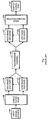
- Fig. 4 illustrates a simple exemplary decision-making flow for selecting the excitation signal.
- Step 401 corresponds to calculating a long-term correlation gain for the high band signal
- step 402 corresponds to calculating a long-term correlation gain for the low band signal.
- Calculating long-term correlation gains is known as such from the technology of long-term prediction (LTP).
- LTP long-term prediction
- steps 403 and 404 the calculated long-term correlation gains for the high and low band signals respectively are compared against certain predetermined threshold values.
- the exact way in which such threshold values have been determined is not important to the present invention; typically certain selected threshold values result from experimenting.
- the meaning of the threshold values is to classify signals as voiced or unvoiced.
- a long-term correlation gain calculated for a certain signal is lower than the corresponding threshold value, the signal is considered to be unvoiced. If the calculated long-term correlation gain is (equal to or) greater than the threshold value, the signal in question is considered to be voiced.
- steps 401 and 403 of fig. 4 are executed in the high band signal analysis block 302 and steps 402 and 404 of fig. 4 are executed in the low band signal analysis block 303.
- the following step 405 is a comparison between the above-or-below-threshold results coming from steps 403 and 404. If the low band is considered to be voiced and the high band unvoiced, the random excitation is selected at step 406. In other cases the resampled low band excitation is selected at step 407. Steps 405, 406 and 407 of fig. 4 correspond to activity in the functional block 304 of fig. 3.
- the excitation selection switch 502 is now arranged to select one of three possible excitation signal sources and to transmit excitation information towards a receiving device.
- the excitation information meant in fig. 5 differs from the excitation selection signal of fig. 3 in that in addition to the simple alternatives "selected resampled low band excitation" or "selected random excitation” it must, when necessary, be able to convey some information about the selected periodic excitation coming from block 501. The exact way in which such information is conveyed is not important to the present invention.
- Prior art solutions describing one-band LPC encoding and decoding solutions is widely known to suggest and discuss transmitting such information in general.
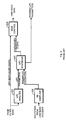
- Fig. 6 illustrates an exemplary decision flow in analogy with fig. 4. This time a negative finding at step 405 leads to step 601, after which if the low band is considered to be unvoiced and the high band voiced, the periodic excitation is selected at step 602. In other cases the resampled low band excitation is selected at step 603. In other words, situations that lead to selecting the resampled low band excitation are those where the high and low band signals are similar in the sense that either both are voiced or both are unvoiced. Steps 405, 406, 601,602 and 603 of fig. 6 correspond to activity in the functional block 502 of fig. 5.
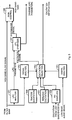
- Fig. 7 illustrates a solution to the problem of excitation signal energy mismatch.
- a local excitation signal generator 701 where "local” means that it generates an excitation signal for the purposes of the high band encoder without direct reference to the LPC encoding of the low band, is augmented with a gain control functionality 702 that receives control information from the low band excitation signal resampling block 305.
- the task of the gain control functionality 702 is to scale the locally generated excitation signal onto a level at which its signal energy is within a predetermined tolerance around a measured signal energy of the low band excitation signal. This ensures that whatever selection is made at the excitation selection switch 304, the signal power of the selected excitation signal will not radically change from the level of the low band excitation signal. Extreme mismatches between a selected excitation signal and the high band LPC residual can be avoided, as long as a basic assumption holds according to which the low and high band LPC residuals resemble each other in terms of signal energy.
- the LPC encoding process handles the input signal in discrete, consecutive sample trains.
- the excitation signals come in short pieces so that the finite number of samples that constitute one piece of an excitation signal may be expressed as a vector.
- a low band excitation vector 1b_exc
- rand_exc a corresponding random excitation vector
- exc_energy, rand_energy and scale_factor that describe the squared energy of the low band excitation signal, the squared energy of the random excitation signal and the scaling factor respectively, we may give the following pseudocode representation of the excitation gain scaling process:
- x T x means an inner product (dot product) of vector x
- SQRT(x) means the square root of x.
- the operator * on the last line of the pseudocode listing is a plain multiplication operator that is used e.g. in a product of a scalar and a vector. Comments not affecting the flow of execution are displayed between /*- and */-signs.
- the arrangement of fig. 7 can be inserted into the appropriate location of any of the arrangements of figs. 3 and 5. If there are several local excitation signal sources like in fig. 5, they may all utilise a single, common gain control functionality or each of them may be equipped with a gain control functionality of its own.
- the order of the functionalities is not necessarily that presented in fig. 7; for example it is possible to place the gain control functionality 702 after the excitation selection switch 304, in which case it should naturally be arranged to perform some true scaling only if the resampled low band excitation signal was not selected.
- excitation gain scaling also enhances robustness against errors, or at least helps to minimise the effects of errors.
- the transmitter needs to signal to the receiver at least the information about whether the resampled low band excitation signal or the locally generated random excitation signal was used in the high band encoder. Signalling is typically accomplished by inserting a certain bit value into a signalling field. A transmission error may cause the receiver to interprete the transmitted signal value incorrectly, so that the receiver selects the wrong excitation signal for high band decoding.
- FIG. 8 illustrates the presence of certain signal processing means in a transmitting device according to an embodiment of the invention.
- a transmission chain comprises a series connection of sound recording and digitising means 801, source encoding means 802, channel encoding means 803 and transmitting means 804.
- the sound recording and digitising means 801 are arranged to record and digitise sound.
- the source encoding means 802 are arranged to receive a bit stream representing digitised sound from the sound recording and digitising means 801 and to encode it as efficiently as possible, i.e. so that a very small number of encoded bits could convey the representation of the recorded sound with as high subjective quality as possible.
- the channel encoding means 803 are arranged to receive the source encoded bit stream from the source encoding means 802 and to add redundancy in order to make the bit robust against transmission errors.
- the transmitting means 804 are arranged to receive the channel encoded bit stream from the channel encoding means 803 and to transmit them through an antenna in the form of suitably modulated electromagnetic radiation.
- Control means 805 are provided to control the operation of the functional blocks of the transmission chain.
- the source encoding means 802 comprise band splitting means 811, low band encoding means 812, low band excitation extracting means 813, voicedness analysing means 814, additional excitation generating means 815, excitation gain scaling means 816, excitation selecting means 817, high band encoding means 818 and bit stream multiplexing means 819.
- the band splitting means 811 are arranged at least to separate the audio signal of one (low) band from the audio signal of another (high) band and to deliver the separated signals to the appropriate band-specific encoders.
- Some route must also exist from the band splitting means 811 to voicedness analysing means 814, so that the last-mentioned may examine, whether the separated bands comprise signals of voiced character. This route has been drawn as a direct connection in fig. 8 for reasons of graphical clarity, although the corresponding information would more probably come to the voicedness analysing means 814 through the band-specific encoders.
- the low band encoding means 812 are arranged to receive the separated low band audio signal, to encode it using LPC encoding and to deliver the low band excitation signal (through certain conceptually defined low band excitation extracting means 813, which also include resampling if any is required) to the excitation selecting means 817. If excitation gain scaling is applied, the low band excitation signal is also arranged to be conveyed to the excitation gain scaling means 816, which are arranged to receive a locally generated excitation signal from the additional excitation generating means 815 and to scale its signal energy appropriately.
- the excitation selecting means 817 are arranged to receive the low band excitation signal, the voicedness information and the locally generated excitation signal from blocks 813, 814 and 816 (or 815) respectively, to select the excitation according to the received voicedness information and preprogrammed selection rules, and to deliver the selected excitation signal to the high band encoding means 818 as well as the appropriate excitation signal selection information to the bit stream multiplexing means 819.
- the high band encoding means 818 are arranged to perform high band LPC encoding with the help of the excitation signal received from the excitation selecting means 817.
- the bit stream multiplexing means 819 are arranged to receive the encoding results of the low band encoding means 812 and the high band encoding means 818 and the excitation signal selection information from the excitation selecting means 817.
- the bit stream multiplexing means 819 are additionally arranged to multiplex said information into an appropriate bit stream that represents complete source encoded information, which bit stream can be delivered to the channel encoding means 803.
- FIG. 9 illustrates the presence of certain signal processing means in a receiving device according to an embodiment of the invention.
- a reception chain comprises a series connection of receiving means 901, channel decoding means 902, source decoding means 903 and sound reproducing means 904.
- the receiving means 901 and channel decoding means 902 together perform equalisation, detection and channel decoding, the purpose of which is to convert received electromagnetic radiation into an as reliable copy as possible of what the channel encoder received from the source encoder in a transmitting device.
- the task of the source decoding means 903 is to reverse the effect of source encoding, so that after source decoding the resulting audio signal can be delivered to the sound reproducing means 904 for conversion into acoustic waves.
- Control means 905 are provided to control the operation of the functional blocks of the reception chain.
- the source decoding means 903 comprise bit stream demultiplexing means 911, low band decoding means 912, low band excitation signal extracting means 913, excitation selection checking means 914, additional excitation signal generating means 915, excitation selecting means 916, high band decoding means 917 and band reconstructing means 918.
- bit stream demultiplexing means 911 are arranged to demultiplex the received bit stream and to direct the appropriate portions thereof to the low band decoding means 912, the excitation selection checking means 914 and the high band decoding means 917.
- the low band decoding means 912 are arranged to perform standard LPC decoding for the low band audio signal and to deliver decoding results to the band reconstructing means 918.
- the low band decoding means 912 also deliver the low band excitation signal (through certain conceptually defined low band excitation extracting means 913, which also include resampling if any is required) to the excitation selecting means 916.
- the excitation selection checking means 914 are arranged to examine an appropriate part of the received bit stream to find an indication about whether the high band encoder in the transmitting device used the low band excitation signal or a locally generated excitation signal in encoding the high band.
- the excitation selection checking means 914 are arranged to deliver this indication as an instruction to the excitation selecting means 916.
- the excitation selection checking means 914 also recover the appropriate periodicity information from the received bit stream and deliver it to the additional excitation signal generating means 915.
- the excitation selecting means 916 are arranged to receive the low band excitation signal, the locally generated excitation signal and the excitation selection information from blocks 913, 915 and 914 respectively, to select the appropriate excitation according to the received selection information, and to deliver the selected excitation signal to the high band decoding means 917.
- the receiver need not be affected at all by the detail, whether excitation gain scaling is applied in the transmitter or not.
- the receiver just accepts the excitation selection information and the high band gain information from the transmitter, regardless of the way in which they were produced.
- excitation gain scaling in the transmitter and the resulting enhanced accuracy in quantization of the excitation gain enables the receiver to reproduce the high band audio signal more accurately, but the receiver does not need to know, whether the advantageous circumstances were due to deliberately taken action in the transmitter or just good luck.
- the high band decoding means 917 are arranged to perform LPC decoding within the high band by starting from the encoded high band information received from the bit stream demultiplexing means 911 and with the help of the excitation signal received from the excitation selecting means 916.
- the band reconstructing means 918 are arranged to collect the decoded audio information from the low band decoding means 912 and the high band decoding means 917 and to combine them into a single wideband audio signal that can be delivered to the sound reproducing means 904.
- inventive functionalities can be implemented in many alternative parts of a communication system.
- they may be implemented as a transcoding unit, which can be a located e.g. in a base transceiver station, base station controller, mobile switching centre or media gateway of the communication network. It may thus locate in radio access network or core network.
- the functionalities can also be implemented in terminal devices, such as mobile communicators or personal computers.
Landscapes
- Engineering & Computer Science (AREA)
- Computational Linguistics (AREA)
- Quality & Reliability (AREA)
- Signal Processing (AREA)
- Health & Medical Sciences (AREA)
- Audiology, Speech & Language Pathology (AREA)
- Human Computer Interaction (AREA)
- Physics & Mathematics (AREA)
- Acoustics & Sound (AREA)
- Multimedia (AREA)
- Compression, Expansion, Code Conversion, And Decoders (AREA)
Claims (28)
- Verfahren zum digitalen Codieren von Ton, umfassend die folgenden Schritte:a) Aufteilen (811) eines Eingangssignals in ein primäres Frequenzband und wenigstens ein sekundäres Frequenzband,b) digitales Codieren (812) des Teils des Eingangssignals im primären Frequenzband, undc) digitales Codieren (818) des Teils des Eingangssignals im sekundären Band oder in den sekundären Frequenzbändern;
dadurch gekennzeichnet, dass es die folgenden Schritte umfasst:d) Überprüfen (302, 303, 814) von bestimmten Charakteristiken des Eingangssignals im primären Frequenzband und entsprechenden Charakteristiken des Eingangssignals in wenigstens einem sekundären Frequenzband, um herauszufinden, ob eine gewisse Ähnlichkeit dazwischen besteht, unde) in Abhängigkeit von den Ergebnissen solch einer Überprüfung, entwedere1) Extrahieren (305, 813) von bestimmten kennzeichnenden Merkmalen des Prozesses, der auf die Codierung des Eingangssignals im primären Frequenzband angewendet wurde, und Verwenden solcher extrahierter kennzeichnender Merkmale in Schritt c), odere2) Ersetzen (306, 501, 701, 815) solcher extrahierter kennzeichnender Merkmale durch einen lokal erzeugten unabhängigen Satz von entsprechenden Merkmalen in Schritt c). - Verfahren nach Anspruch 1, dadurch gekennzeichnet, dass:- Schritt b) dem Anwenden einer linearen Prädiktionscodierung (812) auf das Eingangssignal im primären Frequenzband entspricht und die Erzeugung eines Anregungssignals des primären Frequenzbandes einbezieht,- Schritt c) dem Anwenden einer linearen Pradiktionscodierung (818) auf das Eingangssignal im sekundären Frequenzband entspricht und die Verwendung (307) eines Anregungssignals des sekundären Frequenzbandes einbezieht,- Schritt e1) dem Extrahieren (305, 813) des Anregungssignals des primären Frequenzbandes und Liefern des Anregungssignals des primären Frequenzbandes oder eines Derivats davon zur Verwendung als das Anregungssignal des sekundären Frequenzbandes entspricht, und- Schritt e2) dem Erzeugen (306, 501, 701, 815) des Anregungssignals des sekundären Frequenzbandes unabhängig vom Anregungssignal des primären Frequenzbandes entspricht.
- Verfahren nach Anspruch 2, dadurch gekennzeichnet, dass Schritt e2) dem Erzeugen (306) eines Zufallsanregungssignals entspricht.
- Verfahren nach Anspruch 2, dadurch gekennzeichnet, dass Schritt e2) die folgenden Teilschritte umfasst:- Überprüfen (814), ob das Eingangssignal in einem sekundären Frequenzband Stimmhaftigkeit aufweist, und in Abhängigkeit von den Ergebnissen solch einer Überprüfung:- Erzeugen (501) eines periodischen Anregungssignals, wenn sich herausstellte, dass das Eingangssignal in einem sekundären Frequenzband Stimmhaftigkeit aufweist, oder- Erzeugen (306) eines Zufallsanregungssignals, wenn sich nicht herausstellte, dass das Eingangssignal in einem sekundären Frequenzband Stimmhaftigkeit aufweist.
- Verfahren nach Anspruch 2, dadurch gekennzeichnet, dass Schritt e1) dem Extrahieren (813) des Anregungssignals des primären Frequenzbandes, Nachabtasten (305) des Anregungssignals des primären Frequenzbandes und Verwenden (307) des nachabgetasteten Anregungssignals des primären Frequenzbandes als das Anregungssignal des sekundären Frequenzbandes entspricht.
- Verfahren nach Anspruch 2, dadurch gekennzeichnet, dass es einen Schritt des Modifizierens (702) des Anregungssignals des sekundären Frequenzbandes, das in Schritt e2) erzeugt wurde, umfasst, um seine Signalenergie mit einer Signalenergie des Anregungssignals des primären Frequenzbandes in Übereinstimmung zu bringen.
- Verfahren nach Anspruch 6, dadurch gekennzeichnet, dass es die folgenden Schritte umfasst:- Extrahieren (813) des Anregungssignals des primären Frequenzbandes,- Berechnen eines ersten Energiewerts, der für eine Signalenergie des Anregungssignals des primären Frequenzbandes repräsentativ ist,- Erzeugen (306, 501, 701, 815) des Anregungssignals des sekundären Frequenzbandes,- Berechnen eines zweiten Energiewerts, der für eine Signalenergie des Anregungssignals des sekundären Frequenzbandes repräsentativ ist, und- Skalieren (702) des Anregungssignals des sekundären Frequenzbandes mit einem Verhältnis des ersten Energiewerts und des zweiten Energiewerts.
- Verfahren nach Anspruch 1, dadurch gekennzeichnet, dass:- Schritt d) dem Überprüfen (401, 402, 403, 404, 405), ob das Eingangssignal im primären Frequenzband Stimmhaftigkeit aufweist und ob das Eingangssignal in einem sekundären Frequenzband Stimmhaftigkeit aufweist, entspricht,- Schritt e1) ausgeführt wird (407), wenn sich herausstellt, dass sowohl das Eingangssignal im primären Frequenzband als auch das Eingangssignal in einem sekundären Frequenzband Stimmhaftigkeit aufweisen, oder wenn sich herausstellt, dass das Eingangssignal im primären Frequenzband keine Stimmhaftigkeit aufweist, und- Schritt e2) ausgeführt wird (406), wenn sich herausstellt, dass das Eingangssignal im primären Frequenzband Stimmhaftigkeit aufweist, und sich herausstellt, dass das Eingangssignal in einem sekundären Frequenzband keine Stimmhaftigkeit aufweist.
- Verfahren nach Anspruch 8, dadurch gekennzeichnet, dass die Überprüfung dessen, ob das Eingangssignal in einem Frequenzband Stimmhaftigkeit aufweist, die folgenden Teilschritte umfasst:- Berechnen (401, 402) einer Langzeitkorrelationsverstärkung für das betreffende Eingangssignal und- Vergleichen (403, 404) der berechneten Langzeitkorrelationsverstärkung mit einem Schwellenwert;derart dass befunden wird, dass das Eingangssignal in einem Frequenzband Stimmhaftigkeit aufweist, wenn sich herausstellt, dass die berechnete Langzeitkorrelationsverstärkung größer als ein entsprechender Schwellenwert ist.
- Verfahren zum Decodieren eines digital codierten Tons, umfassend die folgenden Schritte:a) Empfangen (901, 902, 911) eines codierten Eingangssignals, das in ein primäres Frequenzband und wenigstens ein sekundäres Frequenzband aufgeteilt ist, wobei das sekundäre Frequenzband getrennt vom primären Frequenzband codiert wurde,b) Decodieren (912) des Teils des Eingangssignals im primären Frequenzband, undc) Decodieren (917) des Teils des Eingangssignals im sekundären Frequenzband oder in den sekundären Frequenzbändern;
dadurch gekennzeichnet, dass es die folgenden Schritte umfasst:d) Überprüfen (914) des Eingangssignals, um herauszufinden, welchen Hinweis auf die Verwendung von kennzeichnenden Merkmalen des Prozesses, der auf die Codierung des primären Frequenzbandes im Prozess angewendet wurde, der auf die Codierung des sekundären Frequenzbandes angewendet wurde, das Eingangssignal enthält, unde) in Abhängigkeit von den Ergebnissen solch einer Überprüfung, entwedere1) Extrahieren (913) von bestimmten kennzeichnenden Merkmalen des Prozesses, der auf die Decodierung des Eingangssignals im primären Frequenzband angewendet wird, und Verwenden solcher extrahierter kennzeichnender Merkmale in Schritt c), odere2) Ersetzen (915) solcher extrahierter kennzeichnender Merkmale durch einen lokal erzeugten unabhängigen Satz von entsprechenden Merkmalen in Schritt c). - Verfahren nach Anspruch 10, dadurch gekennzeichnet, dass:- Schritt b) dem Decodieren (912) eines linear prädiktionscodierten Eingangssignals im primären Frequenzband entspricht und die Erzeugung eines Anregungssignals des primären Frequenzbandes einbezieht,- Schritt c) dem Decodieren (917) eines linear prädiktionscodierten Eingangssignals in dem sekundären Frequenzband entspricht und die Verwendung eines Anregungssignals des sekundären Frequenzbandes einbezieht,- Schritt e1) dem Extrahieren (913) des Anregungssignals des primären Frequenzbandes und Liefern des Anregungssignals des primären Frequenzbandes oder eines Derivats davon zur Verwendung als das Anregungssignal des sekundären Frequenzbandes entspricht, und- Schritt e2) dem Erzeugen (915) des Anregungssignals des sekundären Frequenzbandes unabhängig vom Anregungssignal des primären Frequenzbandes entspricht.
- Verfahren nach Anspruch 11, dadurch gekennzeichnet, dass Schritt e2) dem Erzeugen (915) eines Zufallsanregungssignals entspricht.
- Verfahren nach Anspruch 11, dadurch gekennzeichnet, dass Schritt e2) die folgenden Teilschritte umfasst:- Überprüfen (914), ob das Eingangssignal einen Hinweis auf Periodizität im sekundären Frequenzband enthält, und in Abhängigkeit von den Ergebnissen solch einer Überprüfung:- Erzeugen (915) eines periodischen Anregungssignals, wenn das Eingangssignal einen Hinweis auf Periodizität im sekundären Frequenzband enthält, oder- Erzeugen (915) eines Zufallsanregungssignals, wenn das Eingangssignal keinen Hinweis auf Periodizität im sekundären Frequenzband enthält.
- Verfahren nach Anspruch 11, dadurch gekennzeichnet, dass Schritt e1) dem Extrahieren des Anregungssignals des primären Frequenzbandes, Nachabtasten des Anregungssignals des primären Frequenzbandes und Verwenden des nachabgetasteten Anregungssignals des primären Frequenzbandes als das Anregungssignal des sekundären Frequenzbandes entspricht.
- Codiervorrichtung zum digitalen Codieren von Ton zur Übertragung, wobei die Codiervorrichtung umfasst:- Bandteilungsmittel (811), die zum Aufteilen eines Eingangssignals in ein primäres Frequenzband und wenigstens ein sekundäres Frequenzband ausgelegt sind,- einen primären Codierer (812), der zum digitalen Codieren des Teils des Eingangssignals im primären Frequenzband ausgelegt ist, und- einen sekundären Codierer (818), der zum digitalen Codieren des Teils des Eingangssignals in einem sekundären Frequenzband ausgelegt ist;dadurch gekennzeichnet, dass sie umfasst:- Prüfmittel (814), die zum Überprüfen von bestimmten Charakteristiken des Eingangssignals im primären Frequenzband und entsprechenden Charakteristiken des Eingangssignals in wenigstens einem sekundären Frequenzband und zum Anzeigen, ob eine gewisse Ähnlichkeit dazwischen besteht, ausgelegt sind,- Extraktionsmittel (813), die zum Extrahieren von bestimmten kennzeichnenden Merkmalen eines Prozesses, der auf die Codierung des Eingangssignals im primären Frequenzband angewendet wird, zur Verwendung in einem Prozess, der auf die Codierung des Eingangssignals im sekundären Frequenzband angewendet wird, ausgelegt sind, und- Ersetzungsmittel (815), die zum Ersetzen solcher extrahierter kennzeichnender Merkmale durch einen lokal erzeugten unabhängigen Satz von entsprechenden Merkmalen im Prozess, der auf die Codierung des Eingangssignals im sekundären Frequenzband angewendet wird, ausgelegt sind;von welchen die Extraktionsmittel (813) und die Ersetzungsmittel (815) so ausgelegt sind, dass sie in Abhängigkeit von einem Hinweis, der durch die Prüfmittel erzeugt wird, operativ alternativ zueinander sind.
- Codiervorrichtung nach Anspruch 15, dadurch gekennzeichnet, dass:- der primäre Codierer (812) ein linearer Prädiktionscodierer ist, der zum Erzeugen eines Anregungssignals des primären Frequenzbandes imstande ist,- der sekundäre Codierer (818) ein linearer Prädiktionscodierer ist, der zum Verwenden eines Anregungssignals des sekundären Frequenzbandes imstande ist,- die Extraktionsmittel (813) so ausgelegt sind, dass sie ein Anregungssignal des primären Frequenzbandes extrahieren und das Anregungssignal des primären Frequenzbandes oder ein Derivat davon zur Verwendung als das Anregungssignal des sekundären Frequenzbandes liefern, und- die Ersetzungsmittel (815) so ausgelegt sind, dass sie ein Anregungssignal des sekundären Frequenzbandes unabhängig vom Anregungssignal des ersten Frequenzbandes erzeugen.
- Codiervorrichtung nach Anspruch 16, dadurch gekennzeichnet, dass die Ersetzungsmittel (815) so ausgelegt sind, dass sie ein Zufallsanregungssignal erzeugen.
- Codiervorrichtung nach Anspruch 16, dadurch gekennzeichnet, dass die Ersetzungsmittel (815) so ausgelegt sind, dass sie überprüfen, ob das Eingangssignal in einem sekundären Frequenzband Stimmhaftigkeit aufweist, und ein periodisches Anregungssignal erzeugen, wenn sich herausstellt, dass das Eingangssignal in einem sekundären Frequenzband Stimmhaftigkeit aufweist, und ein Zufallsanregungssignal erzeugen, wenn sich nicht herausstellt, dass das Eingangssignal in einem sekundären Frequenzband Stimmhaftigkeit aufweist.
- Codiervorrichtung nach Anspruch 16, dadurch gekennzeichnet, dass die Extraktionsmittel (813) Nachabtastungsmittel (305) umfasst, die zum Nachabtasten des Anregungssignals des primären Frequenzbandes und Liefern des nachabgetasteten Anregungssignals des primären Frequenzbandes zur Verwendung als das Anregungssignal des sekundären Frequenzbandes ausgelegt sind.
- Codiervorrichtung nach Anspruch 16, dadurch gekennzeichnet, dass sie Signalmodifikationsmittel (702) umfasst, die zum Modifizieren des Anregungssignals des sekundären Frequenzbandes, das durch die Ersetzungsmittel (701) erzeugt wurde, um seine Signalenergie mit einer Signalenergie des Anregungssignals des primären Frequenzbandes in Übereinstimmung zu bringen, ausgelegt sind.
- Codiervorrichtung nach Anspruch 20, dadurch gekennzeichnet, dass sie umfasst:- Mittel (813) zum Extrahieren des Anregungssignals des primären Frequenzbandes,- Mittel (702) zum Berechnen eines ersten Energiewerts, der für eine Signalenergie des Anregungssignals des primären Frequenzbandes repräsentativ ist,- Mittel (815) zum Erzeugen des Anregungssignals des sekundären Frequenzbandes,- Mittel (702) zum Berechnen eines zweiten Energiewerts, der für eine Signalenergie des Anregungssignals des sekundären Frequenzbandes repräsentativ ist, und- Mittel (702) zum Skalieren des Anregungssignals des sekundären Frequenzbandes mit einem Verhältnis des ersten Energiewerts und des zweiten Energiewerts.
- Codiervorrichtung nach Anspruch 15, dadurch gekennzeichnet, dass:- die Prüfmittel (814) so ausgelegt sind, dass sie überprüfen, ob das Eingangssignal im primären Frequenzband Stimmhaftigkeit aufweist und ob das Eingangssignal in einem sekundären Frequenzband Stimmhaftigkeit aufweist,- die Extraktionsmittel (813) so ausgelegt sind, dass sie für den Betrieb ausgewählt werden, wenn sich herausstellt, dass sowohl das Eingangssignal im primären Frequenzband als auch das Eingangssignal in einem sekundären Frequenzband Stimmhaftigkeit aufweisen, oder wenn sich herausstellt, dass das Eingangssignal im primären Frequenzband keine Stimmhaftigkeit aufweist, und- die Ersetzungsmittel (815) so ausgelegt sind, dass sie für den Betrieb ausgewählt werden, wenn sich herausstellt, dass das Eingangssignal im primären Frequenzband Stimmhaftigkeit aufweist, und sich herausstellt, dass das Eingangssignal in einem sekundären Frequenzband keine Stimmhaftigkeit aufweist.
- Codiervorrichtung nach Anspruch 22, dadurch gekennzeichnet, dass die Prüfmittel (814) so ausgelegt sind, dass sie Langzeitkorrelationsverstärkungen für Eingangssignale berechnen und die berechneten Langzeitkorrelationsverstärkungen mit Schwellenwerten vergleichen, derart dass befunden wird, dass das Eingangssignal in einem Frequenzband Stimmhaftigkeit aufweist, wenn sich herausstellt, dass die berechnete Langzeitkorrelationsverstärkung größer als ein entsprechender Schwellenwert ist.
- Decodiervorrichtung zum Decodieren eines digital codierten Tons, umfassend:- Empfangsmittel (901, 902, 911), die zum Empfangen eines codierten Eingangssignals, das in ein primäres Frequenzband und wenigstens ein sekundäres Frequenzband aufgeteilt ist, ausgelegt sind, wobei das sekundäre Frequenzband getrennt vom primären Frequenzband codiert wurde,- einen primären Decodierer (912), der zum Decodieren des Teils des Eingangssignals im primären Frequenzband ausgelegt ist, und- einen sekundären Decodierer (917), der zum Decodieren des Teils des Eingangssignals in einem sekundären Frequenzband ausgelegt ist;dadurch gekennzeichnet, dass sie umfasst:- Prüfmittel (914), die zum Überprüfen des Eingangssignals und zum Herausfinden, welchen Hinweis auf die Verwendung von kennzeichnenden Merkmalen des Prozesses, der auf die Codierung des Eingangssignals im primären Frequenzband im Prozess angewendet wurde, der auf die Codierung des sekundären Frequenzbandes angewendet wurde, das Eingangssignal enthält, ausgelegt sind,- Extraktionsmittel (913), die zum Extrahieren von bestimmten kennzeichnenden Merkmalen eines Prozesses, der auf die Decodierung des Eingangssignals im primären Frequenzband angewendet wird, und zum Verwenden solcher kennzeichnender Merkmale in einem Prozess, der auf die Decodierung des Eingangssignals im primären Frequenzband angewendet wird, ausgelegt sind, und- Ersetzungsmittel (915), die zum Ersetzen solcher extrahierter kennzeichnender Merkmale durch einen lokal erzeugten unabhängigen Satz von entsprechenden Merkmalen im Prozess, der auf die Decodierung des Einfangssignals im primären Frequenzband angewendet wird, ausgelegt sind;von welchen die Extraktionsmittel (913) und die Ersetzungsmittel (915) in Abhängigkeit von einem Hinweis, der durch die Prüfmittel gefunden wird, operativ alternativ zueinander sind.
- Decodiervorrichtung nach Anspruch 24, dadurch gekennzeichnet, dass:- der primäre Decodierer (912) so ausgelegt ist, dass er ein linear prädiktionscodiertes Eingangssignal im primären Frequenzband decodiert und ein Anregungssignal des primären Frequenzbandes erzeugt,- der sekundäre Decodierer (917) so ausgelegt ist, dass er ein linear prädiktionscodiertes Eingangssignal in einem sekundären Frequenzband decodiert und ein Anregungssignal des sekundären Frequenzbandes verwendet,- die Extraktionsmittel (913) so ausgelegt sind, dass sie das Anregungssignal des primären Frequenzbandes extrahieren und das Anregungssignal des primären Frequenzbandes oder ein Derivat davon als das Anregungssignal des sekundären Frequenzbandes an den sekundären Decodierer liefern, und- die Ersetzungsmittel (915) so ausgelegt sind, dass sie das Anregungssignal des sekundären Frequenzbandes unabhängig vom Anregungssignal des ersten Frequenzbandes erzeugen.
- Decodiervorrichtung nach Anspruch 25, dadurch gekennzeichnet, dass die Ersetzungsmittel (915) so ausgelegt sind, dass sie ein Zufallsanregungssignal erzeugen.
- Decodiervorrichtung nach Anspruch 25, dadurch gekennzeichnet, dass die Ersetzungsmittel (915) so ausgelegt sind, dass sie überprüfen, ob das Eingangssignal einen Hinweis auf Periodizität im sekundären Frequenzband enthält, und in Abhängigkeit von den Ergebnissen solch einer Überprüfung ein periodisches Anregungssignal erzeugen, wenn das Eingangssignal einen Hinweis auf Periodizität im sekundären Frequenzband enthält, oder ein Zufallsanregungssignal erzeugen, wenn das Eingangssignal keinen Hinweis auf Periodizität im sekundären Frequenzband enthält.
- Decodiervorrichtung nach Anspruch 25, dadurch gekennzeichnet, dass die Extraktionsmittel (913) Nachabtastungsmittel umfassen, die zum Nachabtasten des Anregungssignals des primären Frequenzbandes und zum Liefern des nachabgetasteten Anregungssignals des primären Frequenzbandes zur Verwendung als Anregungssignal des sekundären Frequenzbandes ausgelegt sind.
Priority Applications (1)
| Application Number | Priority Date | Filing Date | Title |
|---|---|---|---|
| EP07105690A EP1806738A1 (de) | 2003-07-14 | 2004-07-02 | Verbesserte Anregung für Höherband-Kodierung in einem Codec basierend auf Frequenzbandtrennungs-Kodierungsverfahren |
Applications Claiming Priority (2)
| Application Number | Priority Date | Filing Date | Title |
|---|---|---|---|
| FI20031069A FI118550B (fi) | 2003-07-14 | 2003-07-14 | Parannettu eksitaatio ylemmän kaistan koodaukselle koodekissa, joka käyttää kaistojen jakoon perustuvia koodausmenetelmiä |
| FI20031069 | 2003-07-14 |
Related Child Applications (1)
| Application Number | Title | Priority Date | Filing Date |
|---|---|---|---|
| EP07105690A Division EP1806738A1 (de) | 2003-07-14 | 2004-07-02 | Verbesserte Anregung für Höherband-Kodierung in einem Codec basierend auf Frequenzbandtrennungs-Kodierungsverfahren |
Publications (2)
| Publication Number | Publication Date |
|---|---|
| EP1498873A1 EP1498873A1 (de) | 2005-01-19 |
| EP1498873B1 true EP1498873B1 (de) | 2007-04-11 |
Family
ID=27636101
Family Applications (2)
| Application Number | Title | Priority Date | Filing Date |
|---|---|---|---|
| EP04396043A Expired - Lifetime EP1498873B1 (de) | 2003-07-14 | 2004-07-02 | Verbesserte Anregung für Höherband-Kodierung in einem Codec basierend auf Frequenzbandtrennungs-Kodierungsverfahren |
| EP07105690A Withdrawn EP1806738A1 (de) | 2003-07-14 | 2004-07-02 | Verbesserte Anregung für Höherband-Kodierung in einem Codec basierend auf Frequenzbandtrennungs-Kodierungsverfahren |
Family Applications After (1)
| Application Number | Title | Priority Date | Filing Date |
|---|---|---|---|
| EP07105690A Withdrawn EP1806738A1 (de) | 2003-07-14 | 2004-07-02 | Verbesserte Anregung für Höherband-Kodierung in einem Codec basierend auf Frequenzbandtrennungs-Kodierungsverfahren |
Country Status (4)
| Country | Link |
|---|---|
| US (1) | US7376554B2 (de) |
| EP (2) | EP1498873B1 (de) |
| DE (1) | DE602004005784T2 (de) |
| FI (1) | FI118550B (de) |
Cited By (3)
| Publication number | Priority date | Publication date | Assignee | Title |
|---|---|---|---|---|
| JP2008535026A (ja) * | 2005-04-01 | 2008-08-28 | クゥアルコム・インコーポレイテッド | 音声信号の高帯域部分を符合化及び復号する方法及び装置 |
| US9043214B2 (en) | 2005-04-22 | 2015-05-26 | Qualcomm Incorporated | Systems, methods, and apparatus for gain factor attenuation |
| RU2679346C2 (ru) * | 2013-10-14 | 2019-02-07 | Квэлкомм Инкорпорейтед | Способ, аппарат, устройство, компьютерно-читаемый носитель для расширения полосы частот аудиосигнала с использованием масштабируемого возбуждения верхней полосы |
Families Citing this family (23)
| Publication number | Priority date | Publication date | Assignee | Title |
|---|---|---|---|---|
| KR100657916B1 (ko) * | 2004-12-01 | 2006-12-14 | 삼성전자주식회사 | 주파수 대역간의 유사도를 이용한 오디오 신호 처리 장치및 방법 |
| KR100707174B1 (ko) * | 2004-12-31 | 2007-04-13 | 삼성전자주식회사 | 광대역 음성 부호화 및 복호화 시스템에서 고대역 음성부호화 및 복호화 장치와 그 방법 |
| US20090319277A1 (en) * | 2005-03-30 | 2009-12-24 | Nokia Corporation | Source Coding and/or Decoding |
| UA95776C2 (ru) * | 2005-04-01 | 2011-09-12 | Квелкомм Инкорпорейтед | Система, способ и устройство генерирования возбуждения в диапазоне высоких частот |
| US9454974B2 (en) * | 2006-07-31 | 2016-09-27 | Qualcomm Incorporated | Systems, methods, and apparatus for gain factor limiting |
| US8532984B2 (en) * | 2006-07-31 | 2013-09-10 | Qualcomm Incorporated | Systems, methods, and apparatus for wideband encoding and decoding of active frames |
| US20100017197A1 (en) * | 2006-11-02 | 2010-01-21 | Panasonic Corporation | Voice coding device, voice decoding device and their methods |
| US8639500B2 (en) * | 2006-11-17 | 2014-01-28 | Samsung Electronics Co., Ltd. | Method, medium, and apparatus with bandwidth extension encoding and/or decoding |
| US8005671B2 (en) | 2006-12-04 | 2011-08-23 | Qualcomm Incorporated | Systems and methods for dynamic normalization to reduce loss in precision for low-level signals |
| KR101379263B1 (ko) * | 2007-01-12 | 2014-03-28 | 삼성전자주식회사 | 대역폭 확장 복호화 방법 및 장치 |
| EP2227682A1 (de) * | 2007-11-06 | 2010-09-15 | Nokia Corporation | Ein kodierer |
| KR101238239B1 (ko) | 2007-11-06 | 2013-03-04 | 노키아 코포레이션 | 인코더 |
| JPWO2009084221A1 (ja) * | 2007-12-27 | 2011-05-12 | パナソニック株式会社 | 符号化装置、復号装置およびこれらの方法 |
| BRPI0915358B1 (pt) * | 2008-06-13 | 2020-04-22 | Nokia Technologies Oy | método e aparelho para a ocultação de erro de quadro em dados de áudio codificados usando codificação de extensão |
| CN101751926B (zh) * | 2008-12-10 | 2012-07-04 | 华为技术有限公司 | 信号编码、解码方法及装置、编解码系统 |
| EP3998606B8 (de) | 2009-10-21 | 2022-12-07 | Dolby International AB | Überabtastung in einer kombinierten umsetzer-filterbank |
| US8600737B2 (en) | 2010-06-01 | 2013-12-03 | Qualcomm Incorporated | Systems, methods, apparatus, and computer program products for wideband speech coding |
| US8924200B2 (en) * | 2010-10-15 | 2014-12-30 | Motorola Mobility Llc | Audio signal bandwidth extension in CELP-based speech coder |
| US8868432B2 (en) * | 2010-10-15 | 2014-10-21 | Motorola Mobility Llc | Audio signal bandwidth extension in CELP-based speech coder |
| KR20120046627A (ko) * | 2010-11-02 | 2012-05-10 | 삼성전자주식회사 | 화자 적응 방법 및 장치 |
| US9077604B2 (en) * | 2011-01-20 | 2015-07-07 | Stuart E. Goller | High speed information transfer method and system |
| US9837089B2 (en) * | 2015-06-18 | 2017-12-05 | Qualcomm Incorporated | High-band signal generation |
| US10847170B2 (en) | 2015-06-18 | 2020-11-24 | Qualcomm Incorporated | Device and method for generating a high-band signal from non-linearly processed sub-ranges |
Family Cites Families (4)
| Publication number | Priority date | Publication date | Assignee | Title |
|---|---|---|---|---|
| SE512719C2 (sv) * | 1997-06-10 | 2000-05-02 | Lars Gustaf Liljeryd | En metod och anordning för reduktion av dataflöde baserad på harmonisk bandbreddsexpansion |
| US6182031B1 (en) * | 1998-09-15 | 2001-01-30 | Intel Corp. | Scalable audio coding system |
| US7330814B2 (en) * | 2000-05-22 | 2008-02-12 | Texas Instruments Incorporated | Wideband speech coding with modulated noise highband excitation system and method |
| BRPI0206395B1 (pt) * | 2001-11-14 | 2017-07-04 | Panasonic Intellectual Property Corporation Of America | Decoding device, coding device, communication system constituting a coding device and a coding device, decoding method, coding method, communication method for a system established by a coding device and a decoding device , and recording media |
-
2003
- 2003-07-14 FI FI20031069A patent/FI118550B/fi active IP Right Grant
-
2004
- 2004-07-02 EP EP04396043A patent/EP1498873B1/de not_active Expired - Lifetime
- 2004-07-02 DE DE602004005784T patent/DE602004005784T2/de not_active Expired - Fee Related
- 2004-07-02 EP EP07105690A patent/EP1806738A1/de not_active Withdrawn
- 2004-07-14 US US10/891,846 patent/US7376554B2/en not_active Expired - Lifetime
Cited By (11)
| Publication number | Priority date | Publication date | Assignee | Title |
|---|---|---|---|---|
| JP2008535026A (ja) * | 2005-04-01 | 2008-08-28 | クゥアルコム・インコーポレイテッド | 音声信号の高帯域部分を符合化及び復号する方法及び装置 |
| US8069040B2 (en) | 2005-04-01 | 2011-11-29 | Qualcomm Incorporated | Systems, methods, and apparatus for quantization of spectral envelope representation |
| US8078474B2 (en) | 2005-04-01 | 2011-12-13 | Qualcomm Incorporated | Systems, methods, and apparatus for highband time warping |
| US8140324B2 (en) | 2005-04-01 | 2012-03-20 | Qualcomm Incorporated | Systems, methods, and apparatus for gain coding |
| US8244526B2 (en) | 2005-04-01 | 2012-08-14 | Qualcomm Incorporated | Systems, methods, and apparatus for highband burst suppression |
| US8260611B2 (en) | 2005-04-01 | 2012-09-04 | Qualcomm Incorporated | Systems, methods, and apparatus for highband excitation generation |
| US8332228B2 (en) | 2005-04-01 | 2012-12-11 | Qualcomm Incorporated | Systems, methods, and apparatus for anti-sparseness filtering |
| US8364494B2 (en) | 2005-04-01 | 2013-01-29 | Qualcomm Incorporated | Systems, methods, and apparatus for split-band filtering and encoding of a wideband signal |
| US8484036B2 (en) | 2005-04-01 | 2013-07-09 | Qualcomm Incorporated | Systems, methods, and apparatus for wideband speech coding |
| US9043214B2 (en) | 2005-04-22 | 2015-05-26 | Qualcomm Incorporated | Systems, methods, and apparatus for gain factor attenuation |
| RU2679346C2 (ru) * | 2013-10-14 | 2019-02-07 | Квэлкомм Инкорпорейтед | Способ, аппарат, устройство, компьютерно-читаемый носитель для расширения полосы частот аудиосигнала с использованием масштабируемого возбуждения верхней полосы |
Also Published As
| Publication number | Publication date |
|---|---|
| DE602004005784T2 (de) | 2007-08-16 |
| US7376554B2 (en) | 2008-05-20 |
| US20050065783A1 (en) | 2005-03-24 |
| FI20031069L (fi) | 2005-01-15 |
| EP1806738A1 (de) | 2007-07-11 |
| FI118550B (fi) | 2007-12-14 |
| EP1498873A1 (de) | 2005-01-19 |
| DE602004005784D1 (de) | 2007-05-24 |
| FI20031069A0 (fi) | 2003-07-14 |
Similar Documents
| Publication | Publication Date | Title |
|---|---|---|
| EP1498873A1 (de) | Verbesserte Anregung für Höherband-Kodierung in einem Kodec basierend auf Frequenzbandtrennungs-Kodierungsverfahren | |
| KR101513184B1 (ko) | 계층적 디코딩 구조에서의 디지털 오디오 신호의 송신 에러에 대한 은닉 | |
| CN101512639B (zh) | 用于语音/音频发送器和接收器的方法和设备 | |
| JP5062937B2 (ja) | オーディオ信号における伝送エラーの抑止シミュレーション | |
| EP2492911B1 (de) | Audiokodierungsvorrichtung, dekodierungsvorrichtung, verfahren, schaltung und programm | |
| US9280980B2 (en) | Efficient encoding/decoding of audio signals | |
| JP2006099124A (ja) | デジタル無線チャネル上の自動音声/話者認識 | |
| IL135192A (en) | Method and system for speech reconstruction from speech recognition features | |
| JP2009069856A (ja) | 音声コーデックにおける擬似高帯域信号の推定方法 | |
| MX2008009088A (es) | Aparato y metodo para codificar y descodificar señal. | |
| MX2011000383A (es) | Esquema de codificacion/decodificacion de audio a baja tasa de bits con pre-procesamiento comun. | |
| JP2013541731A (ja) | 過渡フレームの符号化及び復号化 | |
| US12475902B2 (en) | Method and system for data-hiding within audio transmissions | |
| JP4874464B2 (ja) | 遷移音声フレームのマルチパルス補間的符号化 | |
| JP2016505903A (ja) | 周波数拡張されたオーディオ信号を生成するためのデコーダ、復号化方法、符号化された信号を生成するためのエンコーダ、およびコンパクトな選択サイド情報を使用する符号化方法 | |
| US8862465B2 (en) | Determining pitch cycle energy and scaling an excitation signal | |
| KR20030011912A (ko) | 오디오 코딩 | |
| JP2013076871A (ja) | 音声符号化装置及びプログラム、音声復号装置及びプログラム、並びに、音声符号化システム | |
| Gomez et al. | Recognition of coded speech transmitted over wireless channels | |
| CN102804263A (zh) | 编码方法、解码方法、利用了这些方法的装置、程序 | |
| US8762136B2 (en) | System and method of speech compression using an inter frame parameter correlation | |
| Hosoda et al. | Speech bandwidth extension using data hiding based on discrete Hartley transform domain | |
| Hasanabadi | MFCC-GAN codec: a new AI-based audio coding | |
| Tyrberg | Data Transmission over Speech Coded Voice Channels | |
| Soheili | Analysis by synthesis coding of speech signals at 8 kb/s and below |
Legal Events
| Date | Code | Title | Description |
|---|---|---|---|
| PUAI | Public reference made under article 153(3) epc to a published international application that has entered the european phase |
Free format text: ORIGINAL CODE: 0009012 |
|
| AK | Designated contracting states |
Kind code of ref document: A1 Designated state(s): AT BE BG CH CY CZ DE DK EE ES FI FR GB GR HU IE IT LI LU MC NL PL PT RO SE SI SK TR |
|
| AX | Request for extension of the european patent |
Extension state: AL HR LT LV MK |
|
| 17P | Request for examination filed |
Effective date: 20050623 |
|
| AKX | Designation fees paid |
Designated state(s): DE FR GB |
|
| GRAP | Despatch of communication of intention to grant a patent |
Free format text: ORIGINAL CODE: EPIDOSNIGR1 |
|
| RTI1 | Title (correction) |
Free format text: IMPROVED EXCITATION FOR HIGHER BAND CODING IN A CODEC UTILIZING FREQUENCY BAND SPLIT CODING METHODS |
|
| GRAS | Grant fee paid |
Free format text: ORIGINAL CODE: EPIDOSNIGR3 |
|
| GRAA | (expected) grant |
Free format text: ORIGINAL CODE: 0009210 |
|
| AK | Designated contracting states |
Kind code of ref document: B1 Designated state(s): DE FR GB |
|
| REG | Reference to a national code |
Ref country code: GB Ref legal event code: FG4D |
|
| REF | Corresponds to: |
Ref document number: 602004005784 Country of ref document: DE Date of ref document: 20070524 Kind code of ref document: P |
|
| ET | Fr: translation filed | ||
| PLBE | No opposition filed within time limit |
Free format text: ORIGINAL CODE: 0009261 |
|
| STAA | Information on the status of an ep patent application or granted ep patent |
Free format text: STATUS: NO OPPOSITION FILED WITHIN TIME LIMIT |
|
| 26N | No opposition filed |
Effective date: 20080114 |
|
| PGFP | Annual fee paid to national office [announced via postgrant information from national office to epo] |
Ref country code: DE Payment date: 20080711 Year of fee payment: 5 |
|
| PGFP | Annual fee paid to national office [announced via postgrant information from national office to epo] |
Ref country code: FR Payment date: 20080718 Year of fee payment: 5 |
|
| PGFP | Annual fee paid to national office [announced via postgrant information from national office to epo] |
Ref country code: GB Payment date: 20080702 Year of fee payment: 5 |
|
| GBPC | Gb: european patent ceased through non-payment of renewal fee |
Effective date: 20090702 |
|
| REG | Reference to a national code |
Ref country code: FR Ref legal event code: ST Effective date: 20100331 |
|
| PG25 | Lapsed in a contracting state [announced via postgrant information from national office to epo] |
Ref country code: FR Free format text: LAPSE BECAUSE OF NON-PAYMENT OF DUE FEES Effective date: 20090731 |
|
| PG25 | Lapsed in a contracting state [announced via postgrant information from national office to epo] |
Ref country code: GB Free format text: LAPSE BECAUSE OF NON-PAYMENT OF DUE FEES Effective date: 20090702 |
|
| PG25 | Lapsed in a contracting state [announced via postgrant information from national office to epo] |
Ref country code: DE Free format text: LAPSE BECAUSE OF NON-PAYMENT OF DUE FEES Effective date: 20100202 |