EP1498968A2 - Unité de piles à combustible, assemblage d' un empilage de piles à combustible et méthode de construction d' un empilage de piles à combustible - Google Patents
Unité de piles à combustible, assemblage d' un empilage de piles à combustible et méthode de construction d' un empilage de piles à combustible Download PDFInfo
- Publication number
- EP1498968A2 EP1498968A2 EP04024895A EP04024895A EP1498968A2 EP 1498968 A2 EP1498968 A2 EP 1498968A2 EP 04024895 A EP04024895 A EP 04024895A EP 04024895 A EP04024895 A EP 04024895A EP 1498968 A2 EP1498968 A2 EP 1498968A2
- Authority
- EP
- European Patent Office
- Prior art keywords
- fuel cell
- fluid
- cell unit
- contact plate
- unit
- Prior art date
- Legal status (The legal status is an assumption and is not a legal conclusion. Google has not performed a legal analysis and makes no representation as to the accuracy of the status listed.)
- Granted
Links
- 239000000446 fuel Substances 0.000 title claims abstract description 304
- 238000004519 manufacturing process Methods 0.000 title claims abstract description 13
- 239000012530 fluid Substances 0.000 claims abstract description 227
- 239000003792 electrolyte Substances 0.000 claims abstract description 48
- 229910052751 metal Inorganic materials 0.000 claims abstract description 18
- 239000002184 metal Substances 0.000 claims abstract description 18
- 238000007789 sealing Methods 0.000 claims description 24
- 238000000034 method Methods 0.000 claims description 15
- 238000003466 welding Methods 0.000 claims description 11
- 238000000576 coating method Methods 0.000 claims description 10
- 239000011248 coating agent Substances 0.000 claims description 9
- 229910000679 solder Inorganic materials 0.000 claims description 8
- 238000005476 soldering Methods 0.000 claims description 7
- 238000005219 brazing Methods 0.000 claims description 5
- 239000010445 mica Substances 0.000 claims description 5
- 229910052618 mica group Inorganic materials 0.000 claims description 5
- 238000010894 electron beam technology Methods 0.000 claims description 3
- 239000011345 viscous material Substances 0.000 claims description 2
- 239000002737 fuel gas Substances 0.000 description 62
- 239000007800 oxidant agent Substances 0.000 description 31
- 230000001590 oxidative effect Effects 0.000 description 22
- 125000006850 spacer group Chemical group 0.000 description 21
- 239000007789 gas Substances 0.000 description 20
- 238000005452 bending Methods 0.000 description 12
- 239000000463 material Substances 0.000 description 8
- 239000011324 bead Substances 0.000 description 7
- 239000002131 composite material Substances 0.000 description 5
- 238000007650 screen-printing Methods 0.000 description 5
- 239000007787 solid Substances 0.000 description 5
- 229910010293 ceramic material Inorganic materials 0.000 description 4
- 239000002826 coolant Substances 0.000 description 4
- 238000002788 crimping Methods 0.000 description 4
- 230000002349 favourable effect Effects 0.000 description 4
- VNWKTOKETHGBQD-UHFFFAOYSA-N methane Chemical compound C VNWKTOKETHGBQD-UHFFFAOYSA-N 0.000 description 4
- 239000001301 oxygen Substances 0.000 description 4
- 229910052760 oxygen Inorganic materials 0.000 description 4
- -1 oxygen ions Chemical class 0.000 description 4
- 238000007761 roller coating Methods 0.000 description 4
- 229910018072 Al 2 O 3 Inorganic materials 0.000 description 3
- 239000004215 Carbon black (E152) Substances 0.000 description 3
- MYMOFIZGZYHOMD-UHFFFAOYSA-N Dioxygen Chemical compound O=O MYMOFIZGZYHOMD-UHFFFAOYSA-N 0.000 description 3
- 238000004049 embossing Methods 0.000 description 3
- 229930195733 hydrocarbon Natural products 0.000 description 3
- 150000002430 hydrocarbons Chemical class 0.000 description 3
- 238000003825 pressing Methods 0.000 description 3
- XLYOFNOQVPJJNP-UHFFFAOYSA-N water Substances O XLYOFNOQVPJJNP-UHFFFAOYSA-N 0.000 description 3
- PXHVJJICTQNCMI-UHFFFAOYSA-N Nickel Chemical compound [Ni] PXHVJJICTQNCMI-UHFFFAOYSA-N 0.000 description 2
- 239000000919 ceramic Substances 0.000 description 2
- 238000006243 chemical reaction Methods 0.000 description 2
- 238000002485 combustion reaction Methods 0.000 description 2
- 238000010276 construction Methods 0.000 description 2
- 238000006073 displacement reaction Methods 0.000 description 2
- 239000012777 electrically insulating material Substances 0.000 description 2
- 239000011521 glass Substances 0.000 description 2
- 239000001257 hydrogen Substances 0.000 description 2
- 229910052739 hydrogen Inorganic materials 0.000 description 2
- 229910010272 inorganic material Inorganic materials 0.000 description 2
- 239000007769 metal material Substances 0.000 description 2
- 238000003801 milling Methods 0.000 description 2
- 239000000203 mixture Substances 0.000 description 2
- 239000012811 non-conductive material Substances 0.000 description 2
- 239000000843 powder Substances 0.000 description 2
- 239000000047 product Substances 0.000 description 2
- 238000005507 spraying Methods 0.000 description 2
- ODINCKMPIJJUCX-UHFFFAOYSA-N Calcium oxide Chemical compound [Ca]=O ODINCKMPIJJUCX-UHFFFAOYSA-N 0.000 description 1
- UFHFLCQGNIYNRP-UHFFFAOYSA-N Hydrogen Chemical compound [H][H] UFHFLCQGNIYNRP-UHFFFAOYSA-N 0.000 description 1
- 229910004298 SiO 2 Inorganic materials 0.000 description 1
- VYPSYNLAJGMNEJ-UHFFFAOYSA-N Silicium dioxide Chemical compound O=[Si]=O VYPSYNLAJGMNEJ-UHFFFAOYSA-N 0.000 description 1
- 229910000831 Steel Inorganic materials 0.000 description 1
- QVQLCTNNEUAWMS-UHFFFAOYSA-N barium oxide Chemical compound [Ba]=O QVQLCTNNEUAWMS-UHFFFAOYSA-N 0.000 description 1
- 230000015572 biosynthetic process Effects 0.000 description 1
- 229910052810 boron oxide Inorganic materials 0.000 description 1
- 239000011195 cermet Substances 0.000 description 1
- 239000007795 chemical reaction product Substances 0.000 description 1
- 239000000470 constituent Substances 0.000 description 1
- 238000001816 cooling Methods 0.000 description 1
- 238000005520 cutting process Methods 0.000 description 1
- JKWMSGQKBLHBQQ-UHFFFAOYSA-N diboron trioxide Chemical compound O=BOB=O JKWMSGQKBLHBQQ-UHFFFAOYSA-N 0.000 description 1
- 238000010292 electrical insulation Methods 0.000 description 1
- 238000003487 electrochemical reaction Methods 0.000 description 1
- 230000003628 erosive effect Effects 0.000 description 1
- 239000003502 gasoline Substances 0.000 description 1
- 150000002431 hydrogen Chemical class 0.000 description 1
- 238000011031 large-scale manufacturing process Methods 0.000 description 1
- 239000003345 natural gas Substances 0.000 description 1
- 229910052759 nickel Inorganic materials 0.000 description 1
- 230000003647 oxidation Effects 0.000 description 1
- 238000007254 oxidation reaction Methods 0.000 description 1
- TWNQGVIAIRXVLR-UHFFFAOYSA-N oxo(oxoalumanyloxy)alumane Chemical compound O=[Al]O[Al]=O TWNQGVIAIRXVLR-UHFFFAOYSA-N 0.000 description 1
- 125000004430 oxygen atom Chemical group O* 0.000 description 1
- 230000036316 preload Effects 0.000 description 1
- 238000004080 punching Methods 0.000 description 1
- 229910052814 silicon oxide Inorganic materials 0.000 description 1
- 239000007784 solid electrolyte Substances 0.000 description 1
- 229910002076 stabilized zirconia Inorganic materials 0.000 description 1
- 229910001220 stainless steel Inorganic materials 0.000 description 1
- 239000010935 stainless steel Substances 0.000 description 1
- 239000010959 steel Substances 0.000 description 1
- 230000007704 transition Effects 0.000 description 1
Images


Classifications
-
- H—ELECTRICITY
- H01—ELECTRIC ELEMENTS
- H01M—PROCESSES OR MEANS, e.g. BATTERIES, FOR THE DIRECT CONVERSION OF CHEMICAL ENERGY INTO ELECTRICAL ENERGY
- H01M8/00—Fuel cells; Manufacture thereof
- H01M8/02—Details
- H01M8/0202—Collectors; Separators, e.g. bipolar separators; Interconnectors
- H01M8/0204—Non-porous and characterised by the material
- H01M8/0206—Metals or alloys
-
- H—ELECTRICITY
- H01—ELECTRIC ELEMENTS
- H01M—PROCESSES OR MEANS, e.g. BATTERIES, FOR THE DIRECT CONVERSION OF CHEMICAL ENERGY INTO ELECTRICAL ENERGY
- H01M8/00—Fuel cells; Manufacture thereof
- H01M8/02—Details
- H01M8/0202—Collectors; Separators, e.g. bipolar separators; Interconnectors
- H01M8/0204—Non-porous and characterised by the material
- H01M8/0223—Composites
- H01M8/0228—Composites in the form of layered or coated products
-
- H—ELECTRICITY
- H01—ELECTRIC ELEMENTS
- H01M—PROCESSES OR MEANS, e.g. BATTERIES, FOR THE DIRECT CONVERSION OF CHEMICAL ENERGY INTO ELECTRICAL ENERGY
- H01M8/00—Fuel cells; Manufacture thereof
- H01M8/02—Details
- H01M8/0202—Collectors; Separators, e.g. bipolar separators; Interconnectors
- H01M8/0247—Collectors; Separators, e.g. bipolar separators; Interconnectors characterised by the form
-
- H—ELECTRICITY
- H01—ELECTRIC ELEMENTS
- H01M—PROCESSES OR MEANS, e.g. BATTERIES, FOR THE DIRECT CONVERSION OF CHEMICAL ENERGY INTO ELECTRICAL ENERGY
- H01M8/00—Fuel cells; Manufacture thereof
- H01M8/02—Details
- H01M8/0202—Collectors; Separators, e.g. bipolar separators; Interconnectors
- H01M8/0267—Collectors; Separators, e.g. bipolar separators; Interconnectors having heating or cooling means, e.g. heaters or coolant flow channels
-
- H—ELECTRICITY
- H01—ELECTRIC ELEMENTS
- H01M—PROCESSES OR MEANS, e.g. BATTERIES, FOR THE DIRECT CONVERSION OF CHEMICAL ENERGY INTO ELECTRICAL ENERGY
- H01M8/00—Fuel cells; Manufacture thereof
- H01M8/02—Details
- H01M8/0271—Sealing or supporting means around electrodes, matrices or membranes
- H01M8/0273—Sealing or supporting means around electrodes, matrices or membranes with sealing or supporting means in the form of a frame
-
- H—ELECTRICITY
- H01—ELECTRIC ELEMENTS
- H01M—PROCESSES OR MEANS, e.g. BATTERIES, FOR THE DIRECT CONVERSION OF CHEMICAL ENERGY INTO ELECTRICAL ENERGY
- H01M8/00—Fuel cells; Manufacture thereof
- H01M8/02—Details
- H01M8/0271—Sealing or supporting means around electrodes, matrices or membranes
- H01M8/0276—Sealing means characterised by their form
-
- H—ELECTRICITY
- H01—ELECTRIC ELEMENTS
- H01M—PROCESSES OR MEANS, e.g. BATTERIES, FOR THE DIRECT CONVERSION OF CHEMICAL ENERGY INTO ELECTRICAL ENERGY
- H01M8/00—Fuel cells; Manufacture thereof
- H01M8/02—Details
- H01M8/0297—Arrangements for joining electrodes, reservoir layers, heat exchange units or bipolar separators to each other
-
- H—ELECTRICITY
- H01—ELECTRIC ELEMENTS
- H01M—PROCESSES OR MEANS, e.g. BATTERIES, FOR THE DIRECT CONVERSION OF CHEMICAL ENERGY INTO ELECTRICAL ENERGY
- H01M8/00—Fuel cells; Manufacture thereof
- H01M8/24—Grouping of fuel cells, e.g. stacking of fuel cells
- H01M8/2404—Processes or apparatus for grouping fuel cells
-
- H—ELECTRICITY
- H01—ELECTRIC ELEMENTS
- H01M—PROCESSES OR MEANS, e.g. BATTERIES, FOR THE DIRECT CONVERSION OF CHEMICAL ENERGY INTO ELECTRICAL ENERGY
- H01M8/00—Fuel cells; Manufacture thereof
- H01M8/24—Grouping of fuel cells, e.g. stacking of fuel cells
- H01M8/241—Grouping of fuel cells, e.g. stacking of fuel cells with solid or matrix-supported electrolytes
- H01M8/2425—High-temperature cells with solid electrolytes
-
- H—ELECTRICITY
- H01—ELECTRIC ELEMENTS
- H01M—PROCESSES OR MEANS, e.g. BATTERIES, FOR THE DIRECT CONVERSION OF CHEMICAL ENERGY INTO ELECTRICAL ENERGY
- H01M8/00—Fuel cells; Manufacture thereof
- H01M8/10—Fuel cells with solid electrolytes
- H01M8/12—Fuel cells with solid electrolytes operating at high temperature, e.g. with stabilised ZrO2 electrolyte
- H01M2008/1293—Fuel cells with solid oxide electrolytes
-
- H—ELECTRICITY
- H01—ELECTRIC ELEMENTS
- H01M—PROCESSES OR MEANS, e.g. BATTERIES, FOR THE DIRECT CONVERSION OF CHEMICAL ENERGY INTO ELECTRICAL ENERGY
- H01M8/00—Fuel cells; Manufacture thereof
- H01M8/02—Details
- H01M8/0202—Collectors; Separators, e.g. bipolar separators; Interconnectors
- H01M8/0247—Collectors; Separators, e.g. bipolar separators; Interconnectors characterised by the form
- H01M8/0254—Collectors; Separators, e.g. bipolar separators; Interconnectors characterised by the form corrugated or undulated
-
- H—ELECTRICITY
- H01—ELECTRIC ELEMENTS
- H01M—PROCESSES OR MEANS, e.g. BATTERIES, FOR THE DIRECT CONVERSION OF CHEMICAL ENERGY INTO ELECTRICAL ENERGY
- H01M8/00—Fuel cells; Manufacture thereof
- H01M8/02—Details
- H01M8/0271—Sealing or supporting means around electrodes, matrices or membranes
- H01M8/028—Sealing means characterised by their material
- H01M8/0282—Inorganic material
-
- H—ELECTRICITY
- H01—ELECTRIC ELEMENTS
- H01M—PROCESSES OR MEANS, e.g. BATTERIES, FOR THE DIRECT CONVERSION OF CHEMICAL ENERGY INTO ELECTRICAL ENERGY
- H01M8/00—Fuel cells; Manufacture thereof
- H01M8/24—Grouping of fuel cells, e.g. stacking of fuel cells
- H01M8/2465—Details of groupings of fuel cells
- H01M8/247—Arrangements for tightening a stack, for accommodation of a stack in a tank or for assembling different tanks
- H01M8/248—Means for compression of the fuel cell stacks
-
- Y—GENERAL TAGGING OF NEW TECHNOLOGICAL DEVELOPMENTS; GENERAL TAGGING OF CROSS-SECTIONAL TECHNOLOGIES SPANNING OVER SEVERAL SECTIONS OF THE IPC; TECHNICAL SUBJECTS COVERED BY FORMER USPC CROSS-REFERENCE ART COLLECTIONS [XRACs] AND DIGESTS
- Y02—TECHNOLOGIES OR APPLICATIONS FOR MITIGATION OR ADAPTATION AGAINST CLIMATE CHANGE
- Y02E—REDUCTION OF GREENHOUSE GAS [GHG] EMISSIONS, RELATED TO ENERGY GENERATION, TRANSMISSION OR DISTRIBUTION
- Y02E60/00—Enabling technologies; Technologies with a potential or indirect contribution to GHG emissions mitigation
- Y02E60/30—Hydrogen technology
- Y02E60/50—Fuel cells
-
- Y—GENERAL TAGGING OF NEW TECHNOLOGICAL DEVELOPMENTS; GENERAL TAGGING OF CROSS-SECTIONAL TECHNOLOGIES SPANNING OVER SEVERAL SECTIONS OF THE IPC; TECHNICAL SUBJECTS COVERED BY FORMER USPC CROSS-REFERENCE ART COLLECTIONS [XRACs] AND DIGESTS
- Y02—TECHNOLOGIES OR APPLICATIONS FOR MITIGATION OR ADAPTATION AGAINST CLIMATE CHANGE
- Y02P—CLIMATE CHANGE MITIGATION TECHNOLOGIES IN THE PRODUCTION OR PROCESSING OF GOODS
- Y02P70/00—Climate change mitigation technologies in the production process for final industrial or consumer products
- Y02P70/50—Manufacturing or production processes characterised by the final manufactured product
Definitions
- the present invention relates to a fuel cell unit comprising a cathode-anode-electrolyte unit and a contact plate connected to the cathode-anode-electrolyte unit (KAE unit) is in electrically conductive contact, includes.
- the fuel cell unit operates in the cathode-anode-electrolyte unit an electrochemical reaction, in the course of which the anode of the KAE unit supplied electrons and the cathode of the KAE unit for ionization are taken from oxygen atoms electrons.
- the between arranged the KAE units of two consecutive fuel cell units Contact plates serve to charge balance between the cathode one fuel cell unit and the anode of the adjacent one Fuel cell unit, around the cathode, the electrons required for ionization supply. From the marginal contact plates of the fuel cell block assembly Electric charges can be tapped to them to supply an external useful power circuit.
- the contact plates used in the known fuel cell units are made of solid milled or eroded metal plates between which the KAE units are inserted, so that these contact plates at the same time serve the holder of the KAE units. Further, these plates are with channels provided by the passage of fluids (fuel gas, oxidizing agent and / or coolant) through the fuel cell unit.
- the present invention is therefore based on the object, a fuel cell unit to create the type mentioned, which only a small Manufacturing costs required and thus suitable for mass production is.
- Such a sheet metal part can by one or more forming operations, in particular by embossing and / or deep drawing, from a substantially flat sheet metal blank are produced. These manufacturing methods are for a large-scale production much more suitable and cheaper than the Production of solid metal plates by milling or erosion.
- the fluid flowing through the fluid space may be a fuel gas, an oxidizing agent or a coolant.
- the fluid space except from the fluid guide element from the contact plate and from the cathode-anode electrolyte unit is enclosed.
- the Cathode-anode electrolyte unit of the fuel cell unit to the fluid guide element is arranged.
- the cathode-anode-electrolyte unit between the fluid guide element on the one hand and the contact plate of the same Fuel cell unit or an adjacent fuel cell unit on the other hand is arranged.
- the fuel cell unit according to the invention is already prior to assembly of the Brennstoffzellenblockverbunds particularly easy to handle, when the cathode-anode-electrolyte unit between the fluid guide element and the Contact plate of the same fuel cell unit is held.
- the cathode-anode-electrolyte unit as a coating on the fluid guide element or on the Contact plate of the fuel cell unit is formed.
- the contact plate is formed as a sheet metal part.
- the contact plate of the fuel cell unit in a simple manner by embossing and / or deep drawing from a substantially flat sheet metal blank produce what is more suitable and cost effective for mass production is as the production of solid contact plates by milling or Erode.
- the contact plate and the fluid guide element can in this case a form two-part shell of the fuel cell unit, which is the cathode-anode-electrolyte unit encloses.
- the construction according to the invention of a fuel cell unit is particularly suitable for so-called high-temperature fuel cell units, the one Operating temperature of up to 950 ° C and without external reformer directly with a hydrocarbon fuel gas such as Methane or natural gas or alternatively, using an external Reformers, with a diesel or gasoline fuel can be operated.
- a sheet material is selected whose thermal expansion coefficient compatible with the KAE unit.
- the thickness of the sheet material used is preferably at most about 3 mm, in particular at most about 1 mm.
- the Fluid guide element and the contact plate by welding, preferably by laser welding or by electron beam welding, connected to each other.
- the fluid guide element and the contact plate by soldering, preferably by brazing, connected to each other.
- the fluid guide element has a passage opening for the passage of contact elements (e.g., an adjacent fuel cell unit) to the cathode-anode-electrolyte unit.
- the fuel cell unit To the KAE unit between the fluid guide element and the contact element the fuel cell unit to be able to keep without the anode and the To short circuit the cathode of the same fuel cell unit is advantageously provided that the fluid guide element via an electrically insulating gasket is applied to the cathode-anode-electrolyte unit.
- the fluid guide element formed as a fluid guide frame, which along the entire edge the cathode-anode electrolyte unit via the electrically insulating Gasket is applied to the same.
- the seal between the fluid guide element and the KAE unit comprises mica.
- the seal between the KAE unit and the fluid guide element comprises a flat gasket.
- the seal between the KAE unit and the fluid guide element to a coating the fluid guide element and / or at the cathode-anode-electrolyte unit includes.
- Such a coating can, for example by screen printing, by Roller coating or by spray coating on the fluid guide element or the cathode-anode-electrolyte unit are applied.
- inorganic and ceramic sealing media are used for sealing which is chemically active at an operating temperature of up to 950 ° C resistant, gas-tight and electrically insulating.
- a glass solder can be used, which may be composed, for example, as a known from EP 0 907 215 A1 glass solder, that is 11 to 13% by weight of aluminum oxide (Al 2 O 3 ), 10 to 14% by weight of boron oxide ( BO 2 ), about 5% by weight of calcium oxide (CaO), 23 to 26% by weight of barium oxide (BaO), and about 50% by weight of silicon oxide (SiO 2 ).
- the seal between the KAE unit and the fluid guide element as a movable seal is trained.
- the fluid guide element with the KAE unit connected by beading.
- the required pressing force for the seal between the KAE unit and the fluid guide element independent of an external tension the fuel cell units against each other is preferably provided that the cathode-anode-electrolyte unit and the fluid guide element already due to the geometry of the fuel cell unit and the connection between the fluid guide element and the contact plate of Fuel cell unit are resiliently biased against each other.
- the fluid guide element except for holding the KAE unit also for formation to be able to use of fluid channels through which a fluid of the fuel cell unit supplied or discharged from the same, is at a preferred embodiment of the invention provided that the fluid guide element is provided with at least one fluid passage opening.
- the area surrounding the fluid passage opening of the fluid guide element serves in this case as a fluid guide region of the fluid guide element. From the fluid guide areas of the fluid guide elements in the stacking direction successive fuel cell units then results in a fluid channel.
- the fluid supplied or discharged through the fluid channel may be an oxidizing agent or, preferably, be a fuel gas.
- the required electrical insulation between the contact plates and fluid guide elements adjacent to each other Maintaining fuel cell units is advantageously provided in that the fuel cell unit has an electrically insulating fluid channel seal includes, via which the contact plate of the fuel cell unit the fluid guide element of an adjacent fuel cell unit is present.
- the fuel cell unit a fluid channel seal over which the fluid guide element the fuel cell unit on the contact plate of an adjacent Fuel cell unit is applied.
- Such a fluid channel seal for example, a coating on the Fluid guide element and / or on the contact plate.
- Such a coating can in particular by screen printing, by Roller coating or spray coating on the fluid guide element or the contact plate are applied.
- inorganic and ceramic materials are used as sealing media into consideration, which at the occurring operating temperatures of up to 950 ° C are chemically resistant, gas-tight and electrically insulating.
- a particularly simple construction of the fluid channel seal results when the same includes a flat gasket.
- the fluid channel seal comprises at least two separate sealing elements, in particular can be arranged in different levels.
- the fluid channel seal comprises a sliding seat seal.
- Claim 20 is directed to a fuel cell block assembly, which a Comprises a plurality of fuel cell units according to the invention, the longitudinal follow one another in a stacking direction.
- the fuel cell block composite At least one tensioning element for bracing the fuel cell units covered against each other.
- the fuel cell block assembly may comprise two end plates, which are braced against each other by means of the clamping element.
- a fluid fuel gas, Oxidant or coolant
- a fluid or supply the fluid from the fuel cell block assembly to be able to dissipate, is advantageously provided that at least one of the end plates has at least one fluid passage opening.
- a distortion of the fuel cell units of the fuel cell block assembly against each other by means of a separate clamping element is unnecessary, if it is advantageously provided that the fluid guide element at least one of the fuel cell units with the contact plate of an adjacent Fuel cell unit is connected by beading. These Beading is sufficient to the fuel cell units in their position relative to each other.
- an additional clamping element to do so used to control the contact pressure between the KAE units and to produce the contact plates of the fuel cell block assembly.
- an electrically insulating fluid channel seal is arranged between the Bördelfalz Scheme and the contact plate of the adjacent fuel cell unit.
- the individual parts contact plate, KAE unit and fluid guide element in each case a fuel cell unit assembled and the contact plate and the fluid guide element, for example by welding or soldering, connected to each other To install fuel cell unit.
- the entire fuel cell block assembly is assembled, in which the fuel cell units of the fuel cell block composite preferably by means of at least one clamping element against each other be tense.
- the fuel cell units of the fuel cell block assembly between two End plates arranged and clamped the two end plates against each other become.
- the method described above is suitable for producing the fuel cell block assembly especially when the fluid guide element at least one fuel cell unit on the contact plate of an adjacent Fuel cell unit via a flat gasket or a sliding seat seal is applied.
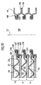
- FIGS. 1 to 8 designated as a whole by 100 fuel cell device comprises a substantially cuboid housing 102 (see FIG. 1), into which an oxidant supply line 104 opens, via the the interior of the housing 102, an oxidizing agent, for example Air or pure oxygen from a feed fan (not shown) supplied under an overpressure of, for example, about 50 mbar becomes.
- an oxidizing agent for example Air or pure oxygen from a feed fan (not shown) supplied under an overpressure of, for example, about 50 mbar becomes.
- an oxidant discharge pipe 105 opens, by which excess oxidizing agent from the interior of the housing 102 is dischargeable.
- Fuel cell block assembly 106 is arranged, which has a lower end plate 108, an upper end plate 110, and a plurality between the lower end plate 108 and the upper end plate 100, along a stacking direction 112 consecutive fuel cell units 114 includes.
- Fuel cell units 114 includes each of the fuel cell units 114 is a substantially plate-shaped cathode-anode-electrolyte unit 116 (in the following short: KAE unit), the between a contact plate 118 and a fluid guide frame 120 is held.
- KAE unit substantially plate-shaped cathode-anode-electrolyte unit
- the KAE unit 116 includes, as shown purely schematically in Fig. 3, a gas-permeable, electrically conductive carrier layer 121, for example, as Grid or mesh of a metallic material, e.g. nickel, formed may be, through the mesh of a fuel gas from a to the carrier layer 121 adjacent fuel gas chamber 124 can pass.
- a gas-permeable, electrically conductive carrier layer 121 for example, as Grid or mesh of a metallic material, e.g. nickel, formed may be, through the mesh of a fuel gas from a to the carrier layer 121 adjacent fuel gas chamber 124 can pass.
- the KAE unit 116 includes a plate-shaped anode 122 disposed on the support layer 121 of an electrically conductive ceramic material such as Ni-ZrO 2 cermet (ceramic-metal mixture) which is porous to the fuel gas from the fuel gas space 124 permitting passage through the anode 122 to the electrolyte 126 adjacent to the anode 122.
- an electrically conductive ceramic material such as Ni-ZrO 2 cermet (ceramic-metal mixture) which is porous to the fuel gas from the fuel gas space 124 permitting passage through the anode 122 to the electrolyte 126 adjacent to the anode 122.
- a fuel gas for example, a hydrocarbon-containing gas mixture or pure hydrogen can be used.
- the electrolyte 126 is preferably formed as a solid electrolyte and, for example formed from yttrium-stabilized zirconia.
- a plate-shaped cathode 128, which is formed of an electrically conductive ceramic material, for example of LaMnO 3 , and having a porosity to an oxidizing agent, such as air or pure oxygen from an oxidant space 130 adjacent to the cathode 128 to allow passage to the electrolyte 126.
- the KAE unit 116 has each one Fuel cell unit 114 a temperature of, for example, about 850 ° C, at which the electrolyte 126 is conductive for oxygen ions.
- the Oxidant from the oxidant space 130 increases at the anode 122 Electrons and gives divalent oxygen ions to the electrolyte 126th which migrate through the electrolyte 126 to the anode 122.
- the fuel gas from the fuel gas chamber 124 through the Oxygen ions from the electrolyte 126 oxidize and thereby give electrons to the anode 122 from.
- the contact plates 118 are used in the reaction of the anode 122nd dissipating electrons from the anode 122 via the support layer 121 or the electrons required for the reaction at the cathode 128 to supply the cathode 128.
- each of the contact plates 118 made of a good electrical conductivity Sheet metal, which (as best seen in Fig. 5 can be seen) with a variety is provided by contact elements 132, which, for example, the shape of adjacent projections and depressions, each with square Have plan, which by the superposition of a first Wave pattern with parallel to the narrow sides 133 of the contact plate 118th directed troughs and wave crests and a second wave pattern with parallel to the long sides 135 of the contact plate 118 directed troughs and wave crests are formed.
- the formed from the contact elements 132 contact pad 134 of the contact plate 118 thus has the structure of one in two mutually perpendicular Directions of corrugated corrugated sheet.
- the contact elements 132 are on the respective contact plate 118 in one Square grid arranged, with adjacent contact elements of the center plane 139 of the contact plate 118 from alternately to different Pages of the contact plate 118 project.
- the from the contact plate 118 after at the top and thus to the anode 122 of the same fuel cell unit 114 associated KAE unit 116 projecting anode-side contact elements are denoted by the reference numeral 132 a, which from the contact plate 118 after down and thus to the cathode 128 of an adjacent fuel cell unit 114 associated KAE unit 116 projecting cathode side Contact elements are designated by the reference numeral 132b.
- the dash-dot lines drawn in FIG. 5 within the contact field 134 give the boundary lines of the contact elements 132 again, longitudinally of which the contact plate 118 cuts its center plane 139.
- Each of the contact elements 132 has a central contact region 137, at which it is electrically conductive with an adjacent KAE unit 116 Contact stands.
- the contact areas 137 of the anode-side contact elements 132 a of a Contact plate 118 are connected to the carrier layer 121 and thus to the anode 122 of the same fuel cell unit 114 associated KAE unit 116 in electrical point contact, so that electrons from the respective anode 122 in the contact plate 118 can get.
- the cathode-side contact elements 132b of the contact plates 118 stand with the cathode 128 of an adjacent fuel cell unit 114 associated KAE unit 116 in electrically conductive point contact, so that electrons can get from the contact plate 118 to the cathode 128.
- the contact plates 118 allow the charge balance between the anodes 122 and cathodes 128 along the stacking direction 112 successive KAE units 116.
- the arranged at the ends of the fuel cell block assembly 106 contact plates 118 are (in a non-illustrated way) with a external circuit connected to those at these marginal contact plates 118 tap resulting electric charges.
- each Contact plate 118 surrounded by a flat flange portion 136, which forms the outer edge of the contact plate 118 and parallel to the median plane 139 of the contact pad 134 aligned, but opposite to the KAE unit 116 is shifted towards, so that in the region of the narrow longitudinal sides 138th the flange portion 136 the underside of the KAE unit 116 on the top the flange portion 136 rests (see in particular Fig. 7).
- the wide side portions 140 of the flange portion 136 each have one Through opening 142 and 144, which the passage of the fuel cell units 114 zu thoroughlydem fuel gas or from the fuel cell units 114 ab complicatdem exhaust, which excess Fuel gas and combustion products, especially water containing, allow.
- the flange region 136 is connected to the contact field arranged offset therefrom 134 connected via a contact pad 134 surrounding slope 146, which at a first bending line 148 to the contact pad 134 and at a second Bend line 150 adjacent to the flange 136.
- Each of the contact plates 118 is formed as a sheet metal part, which consists of a substantially planar, substantially rectangular sheet metal layer Embossing and / or deep drawing as well as by punching out or cutting out the Through openings 142, 144 is formed.
- the fluid guide frame 120 are as sheet metal parts of a substantially levels, formed substantially rectangular sheet metal layer.
- each of the through holes is 154, 156 in a fluid guide frame 120 of a longitudinally the stacking direction 112 extending collar 158, one along a bending line 160 adjacent to the collar 158, perpendicular to the stacking direction 112 extending from the passage opening sealing pad area 162 and one at a bending line 164 to the sealing pad area 162nd adjacent, parallel to the stacking direction 112 aligned channel wall area Surrounded 166.
- the channel wall portion 166 to an outer Edge of the frame 120 adjacent he goes to a bending line 167 in a perpendicular to the stacking direction 112 aligned flange 168 over.
- each of the fluid guide frames 120 between the passage openings 154, 156 in the end regions 152 the fluid guide frame 120 is a substantially rectangular, central Passage opening 170 for the passage of the contact elements 132 of the contact plate 118 of an adjacent fuel cell unit 114.
- the channel wall region 166 goes there, where it is adjacent the passage opening 170 at a bend line 172 in FIG an aligned perpendicular to the stacking direction 112 inner edge region 178 of the fluid guide frame 120 via.
- the inner periphery extends 178 of the fluid guide frame 120 around the passage opening 170th
- the inner edge area 178 goes at its side facing away from the passage opening 170 edge along a bending line 182 in a direction parallel to the stacking direction 112 vertical Wall portion 184 on, which in turn along a bending line 185 in the the outer edge of the fluid guide frame 120 forming flange 168 passes.
- each KAE unit is 116 at the edge of its the fluid guide frame 120 of the same fuel cell unit 114 facing top with a gas-tight, electrically insulating Fuel gas chamber seal 186 provided laterally over the KAE unit 116th survives.
- the fuel gas space seal for example, a flat gasket made of mica include.
- the fuel gas space seal 186 a gas-tight, electrically insulating coating on the underside of the fluid guide frame 120, the screen-printing method or by roller coating on the underside of the inner edge region 178 of the fluid guide frame 120 is applied.
- the two are the through holes 154, 156 of the fluid guide frame 120 surrounding seal bearing areas 162 on its side facing away from the KAE unit 116 top each with a gas channel seal 188 provided.
- the gas channel seal 188 preferably comprises a flat gasket Mica or a gas-tight, electrically insulating coating that acts as a paste by screen printing or by roller coating on the sealing pad area 162 of the fluid guide frame 120 can be applied.
- the fluid guide frame 120 of the fuel cell unit 114 is in turn about the fuel gas space seal 186 on the outer edge of the cathode 128th the KAE unit 116 and with the flange portion 168 on the flange portion 136 of the contact plate 118.
- the flange portion 168 and the flange portion 136 are welded together (e.g., by the laser welding method or the electron beam method) or by Soldering, in particular a brazing, fixed to each other and gas-tight sealed.
- the fuel cell units 114 of the fuel cell stack 106 are along the stacking direction 112 stacked so that the cathode side Contact elements 132b of each contact plate 118 through the passage opening 170 in the fluid guide frame 120 each disposed below Fuel cell unit 114 to the cathode of the KAE unit 116 of the underneath arranged fuel cell unit 114 extend and in electrically conductive Contact with the same contact.
- each contact plate 118 lies on the gas channel seal 188 of the fluid guide frame 120 respectively disposed below Fuel cell unit 114, wherein the collar 158, which the Through opening 154 and 156 in the fluid guide frame 120 surrounds, in the respective corresponding passage opening 142 or 144 of the contact plate 118 extends into it.
- each Fluid guide frame 120 forms a fuel gas guide area.
- the exhaust passage opening 156 surrounding end portion 152 of each fluid guide frame 120 forms an exhaust gas routing area.
- a fuel gas supply line 196 is connected, which through the housing 102 of the fuel cell device 100 passed gas-tight and is connected to a (not shown) fuel gas supply, which the Fuel gas supply line 196, a fuel gas, such as a hydrocarbon-containing Gas or pure hydrogen, under an overpressure of for example about 50 mbar feeds.
- a fuel gas such as a hydrocarbon-containing Gas or pure hydrogen
- the exhaust gas guide regions form the successive fluid guide frame along the stacking direction 112 120 together an exhaust passage 198 which is parallel to the stacking direction 112 is aligned and at its lower end by a the top of the lower end plate 108 of the fuel cell block assembly 106 provided projection 200 is closed.
- the exhaust duct 198 opens into one of the same coaxial Abgasab Wennö réelle 202, which the upper end plate 110 of the fuel cell block assembly 106 interspersed and at its exhaust port 198th remote end is connected to an exhaust gas discharge line 204.
- the exhaust gas discharge line 204 is gas-tight through the housing 102 of the fuel cell device 100 passed and to a (not shown) Exhaust gas treatment unit connected.
- the fuel gas flows through the Fuel gas supply line 196 and the fuel gas supply port 194 in the Brenngaskanal 190 and distributed from there through the interstices between the contact plates 118 and the respective same fuel cell unit 114 associated fluid guide frame 120 to the fuel gas chambers 124th the fuel cell units 114, which in each case by the contact plate 118, the fluid guide frame 120 and the KAE unit 116 of the respective Fuel cell unit 114 are enclosed.
- the fuel gas is at least partially at the respective fuel gas chamber 124 limiting anode 122 of the respective KAE unit 116 oxidized.
- the oxidation product comes together with excess Fuel gas from the fuel gas chambers 124 of the fuel cell units 114 in the exhaust passage 198, from which it through the Abgasabriosö réelle 202 and the exhaust gas discharge line 204 to the exhaust treatment unit (not shown) is dissipated.
- the reaction product for example, water
- excess Fuel gas is supplied to the fuel gas supply to again the fuel cell device 100 to be supplied.
- the oxidant needed for operation of the fuel cell device 100 (For example, air or pure oxygen) is the interior of the Housing 102 is supplied through the oxidant supply line 104.
- oxygen ions formed by the electrolytes 126 to the anodes 122 of the KAE units 116 of the fuel cell units 114 migrate.
- the flow direction of the fuel gas and the exhaust gas through the fuel cell device 100 is in the drawings with simple arrows 210, the Flow direction of the oxidant through the fuel cell device 100 indicated by double arrows 212.
- the flow direction of the oxidant through the oxidant spaces 130 is substantially perpendicular to the flow direction of the fuel gas through the fuel gas chambers 124.
- Connecting screws 214 are provided which through holes 216 in the end plates 108, 110 of the fuel cell block composite 106 enforce and at its end remote from the respective screw head 218 are provided with an external thread 220, in each of which a connecting nut 222 is screwed so that the end plates 108, 110 between the Screw heads 218 and the connecting nuts 222 are clamped and a desired pressing force on the end plates 108, 110 on the stack of Fuel cell units 114 is transferable (see Fig. 2).
- the contact pressure with which the fluid guide frames 120 against the fuel gas chamber seals 186 are pressed against the KAE units 116 will be against - regardless of the external tension by means of the connecting screws 214 and connecting nuts 222 - exclusively by the elastic Preload determines with which the fluid guide frame 120 a Fuel cell unit 114 against the KAE unit 116 of the same fuel cell unit 114 is biased.
- This elastic bias is generated at the time when the Fluid guide frame 120 and the contact plate 118 of the same fuel cell unit 114 fixed to the flange portions 136 and 168 to each other become.
- This elastic biasing force depends on the geometry of the fuel cell units 114 and comes about in that the sum of the Extents of a contact element 132a and the KAE unit 116 with the arranged thereon fuel gas space seal 186 in the stacking direction 112th is slightly larger than the distance that the bottom of the inner edge area 178 of the fluid guide frame 120 in the undeformed state of the fluid guide frame 120 from the center plane of the contact pad 134 of the contact plate 118 would take.
- the fluid guide frame 120 By between the contact plate 118 and the Fluid guide frame 120 clamped KAE unit 116 is the fluid guide frame 120 elastically deformed, which provides an elastic restoring force for Result, which the fluid guide frame 120 against the KAE unit 116th biases.
- the fuel cell block assembly 106 described above becomes as follows assembled:
- the individual fuel cell units 114 are assembled by in each case a KAE unit 116 between a contact plate 118 and a Fluid guide frame 120 is arranged and then to each other adjacent flange portions 136 of the contact plate 118 and the flange 168 of the fluid guide frame 120 gas-tight, for example by welding or soldering, in particular brazing, interconnected become.
- the fuel cell block assembly 106 of the individual Fuel cell units 114 composed by the desired Number of fuel cell units 114 along the stacking direction 112 is stacked and the fuel cell units 114 by means of the end plates 108, 110 and the end plates against each other bracing connecting screws 214 and connecting nuts 222 in their position relative be fixed to each other.
- a illustrated in Fig. 9 second embodiment of a fuel cell device 100 differs from the first described above Embodiment in that the contact plates 118 in the region of the gas channel seals 188 not only on the fluid guide frame 120 'of an adjacent Fuel cell unit 114 abut, but rather by beading connected to this fluid guide frame.
- the collar 158 passes through each fluid guide frame 120 ', the exhaust gas passage opening 144 (or the fuel gas passage opening 142) in the contact plate 118 of the adjacent fuel cell unit 114 and goes to a bend line 224 in a perpendicular to the stacking direction 112 aligned Bördelfalz Scheme 226 over.
- the on the contact plate 118 facing side of the fluid guide frame 120 'arranged gas channel seal 188' is in this second embodiment not in one piece, as in the first described above Embodiment, but formed in two parts and includes a first flat gasket 228 formed between the top of the seal pad 126 the fluid guide frame 120 'and the bottom of the flange portion 136th the contact plate 118 is arranged, and a second flat gasket 230, the between the underside of the hem flange area 226 of the fluid guide frame 120 'and the top of the flange portion 136 of the contact plate 118th is arranged.
- the flat gaskets 228, 230 may be in the form of mica gaskets or gastight, electrically insulating coatings (on the contact plate 118 or be formed on the fluid guide frame 120 ').
- the hem flange area 226 on the fluid guide frame 120 ' forms an undercut, through which the contact plate 118 of each adjacent Fuel cell unit 114 is fixed to the fluid guide frame 120 '.
- a spacer ring of an electric insulating, preferably ceramic, material are arranged.
- the channel wall region 166 'of the fluid guide frame 120' is not, as in the first embodiment, aligned parallel to the stacking direction 112, but rather at an angle of about 45 ° to the stacking direction 112 inclined.
- the extent of the channel wall area 166 'along the stacking direction 112 smaller than in the first embodiment.
- the fuel cell block assembly 106 of the second embodiment of a Fuel cell device 100 is preferably as follows prepared method described:
- fluid guide element contact plate units preassembled, in each case by a fluid guide frame 120 'of a fuel cell unit 114 with the contact plate 118 of an adjacent fuel cell unit by flanging in the region of the fuel gas channel 190 and the exhaust duct 198 is connected.
- the stack becomes the fluid guide frame contact plate units formed so that each contact plate 118 with its flange 136 on the Flange portion 168 of the fluid guide frame 120 'of an adjacent fluid guide frame contact plate unit is applied.
- a third embodiment of a fuel cell device shown in FIG. 10 differs from the second embodiment described above in that the holding plates in the region of the fuel gas space seal 186 not just abut the KAE units 116, but rather are connected by beading with these KAE units 116.
- FIG. 10 closes in this embodiment of the Seal seating area 126 of the fluid guide frame 120 'along a bend line 234 a perpendicular to the stacking direction 112 aligned support area 236, which with its top surface at the bottom of the sealing pad area 126 abuts and in turn at a bend line 238 in a Transitions parallel to the stacking direction 112 aligned channel wall region 166.
- a Bördelfalz Scheme 240 which is perpendicular to the stacking direction 112th is aligned and with its top at the bottom of the carrier layer 121 of the KAE unit 116 is applied.
- the hem flange area 240 on the fluid guide frame 120 ' forms an undercut, through which the KAE unit 116 on the fluid guide frame 120 'of the same fuel cell unit 114 is fixed.
- the third embodiment of a fuel cell device is correct in terms of structure and function with the second embodiment, to the above description in this respect reference is made.
- a fourth embodiment of a fuel cell device shown in FIG. 11 differs from the first embodiment described above in that the gas channel seal in the fourth embodiment not - as in the first embodiment - as having an outer one Clamping acted upon flat gasket is formed, but rather than Sliding seat seal is formed.
- the seal support portion 162 goes to its inner Edge region 178 facing away along a bending line 242 in a parallel to the stacking direction 112 aligned channel wall region 244, which, in turn, faces away from its sealing seating area 162 upper edge along a bending line 246 in a substantially perpendicular to Stacking direction 112 aligned and in the respective passage opening 154th or 156 in the directed shoulder area 248 passes.
- the contact plate 118 has, in contrast to the contact plate of the first Embodiment in this fourth embodiment at each of the through holes 142 and 144 a the respective passage opening annular surrounding, substantially parallel to the stacking direction 112th aligned collar 250, which along a bending line 252 to the each adjacent slope 146 and the flange 136 of the Contact plate 118 'adjacent.
- each one of the channel wall portion 244 annularly surrounding Spacer 252 is arranged, which has a substantially L-shaped Cross-section, with a first leg 254 which on the Seal support portion 162 rests and substantially perpendicular to the Stacking direction 112 is aligned, and with a second leg 256, which on the outside of the channel wall portion 244 and substantially aligned parallel to the stacking direction 112.
- the first leg 254 of the spacer 252 serves as a spacer between the collar 250 of the contact plate 118 'and the Dichtungsetzlage Scheme 162 of the holding plate 120 ".
- the second leg 256 of the spacer 252 serves as a spacer between the collar 250 of the contact plate 118 'and the channel wall portion 244 of the fluid guide frame 120 ".
- the spacer element 252 consists of an electrically insulating material, which at the operating temperature of the fuel cell device 100 of For example, about 850 ° C is solid and stable.
- the spacer element 252 may be formed, for example, of Al 2 O 3 .
- the second leg 256 of the spacer 252 carries the channel wall area 244 of the fluid guide frame 120 "annular sealing bead 256, which defines the gap between the channel wall region 244 and the collar 250 of the contact plate 118 'closes.
- the sealing bead 258 is made of an electrically non-conductive material, at the operating temperature of the fuel cell device 100 of, for example about 850 ° C viscous, but chemically resistant.
- a material for the sealing bead 256 is in particular a glass solder or a glass-like, amorphous material into consideration.
- sealing bead 258 formed from glass solder so he can by applying a paste containing glass powder.
- the contact plate 118 'and the fluid guide frame 120 are also vertical to the stacking direction 112 against each other displaceable, namely to the Distance by which the first leg 254 of the spacer element 252 over the second leg 256 projects perpendicular to the stacking direction 112.
- the collar 250 shifts relative to the fluid guide frame 120 "of FIG the starting position shown in Fig. 11 from perpendicular to the stacking direction 112, so the melted sealing bead 258 continues to provide a gas-tight seal between the contact plate 118 'and the fluid guide frame 120 ".
- Such a sliding seat seal on the fuel gas passage 190 and the exhaust passage 198 is particularly suitable for differences between the individual Components of the fuel cell units 114 (KAE unit 116, Contact plate 118 'and fluid guide frame 120 ") with respect to their thermal To compensate for expansion coefficients.
- the fuel cell block assembly 106 of the fourth embodiment is preferably - as in the first embodiment - this procedure, that first the individual fuel cell units 114 through gas-tight connection of the contact plate 118 'and the fluid guide frame 120 "of the same fuel cell unit 114 are connected to each other and then the finished assembled fuel cell units 114 along the Stacking direction 112 stacked.
- a fifth embodiment of a fuel cell device shown in FIG. 12 differs from the fourth embodiment described above in that except for the gas channel seal 188 "at the fourth Embodiment also the fuel gas space seal 186 'as a sliding seat seal is trained.
- a KAE unit 116 annularly surrounding spacer element 270 is arranged, which has a substantially L-shaped cross-section, with a first Leg 272 which abuts the side wall 268 of the KAE unit 116 and is aligned substantially parallel to the stacking direction 112, and with a second leg 274, which at the top of the KAE unit 116th and at the bottom of the inner edge portion 178 of the fluid guide frame 120 "and substantially perpendicular to the stacking direction 112 is aligned.
- the first leg 272 of the spacer element 270 serves as a spacer between the KAE unit 116 and the curved wall portion 266 of the fluid guide frame 120 ".
- the second leg 274 of the spacer element 270 serves as a spacer between the KAE element 116 and the inner Edge region 178 of the fluid guide frame 120 ".
- the spacer element 270 is made of an electrically insulating material which is solid and stable at the operating temperature of the fuel cell device 100, for example, about 850 ° C, for example, Al 2 O 3 .
- a ring-shaped closed seal member 276 is arranged, which is made of an electrically non-conductive material, which at the operating temperature of the fuel cell device 100 of, for example, approximately 850 ° C viscous, but chemically resistant.
- a material for the sealing element 276 is in particular a glass solder or a glass-like, amorphous material into consideration.
- the sealing member 276 is formed of glass solder, it can by applying a paste containing glass powder on top of the KAE element 116, for example by screen printing.
- the KAE unit 116 shifts relative to the fluid guide frame 120 " from the initial position shown in Fig. 12 from perpendicular to the stacking direction 112 to the left, so ensures the melted seal member 276th further for a gas-tight seal between the KAE unit 116 and the fluid guide frame 120 "while the spacer 270 is leaking the viscous mass of the seal member 276 in the fuel gas space 124 prevented.
- Such a sliding seat seal between the fuel gas chamber 124 and the Oxidant space 130 is particularly suitable for making a difference between the individual components of the fuel cell units 114 (KAE unit 116, contact plate 118 'and fluid guide frame 120 ") with respect to compensate for their thermal expansion coefficient.
- the fifth embodiment of a fuel cell device is correct in terms of structure and function with the fourth embodiment to the above description of which reference is made.
Landscapes
- Chemical & Material Sciences (AREA)
- Life Sciences & Earth Sciences (AREA)
- Engineering & Computer Science (AREA)
- Manufacturing & Machinery (AREA)
- Sustainable Development (AREA)
- Sustainable Energy (AREA)
- Chemical Kinetics & Catalysis (AREA)
- Electrochemistry (AREA)
- General Chemical & Material Sciences (AREA)
- Composite Materials (AREA)
- Fuel Cell (AREA)
- Sampling And Sample Adjustment (AREA)
Applications Claiming Priority (3)
| Application Number | Priority Date | Filing Date | Title |
|---|---|---|---|
| DE10044703A DE10044703B4 (de) | 2000-09-09 | 2000-09-09 | Brennstoffzelleneinheit, Brennstoffzellenblockverbund und Verfahren zum Herstellen eines Brennstoffzellenblockverbunds |
| DE10044703 | 2000-09-09 | ||
| EP01121313A EP1187243B1 (fr) | 2000-09-09 | 2001-09-06 | Unité de pile à combustible, assemblage d'un empilage de piles à combustible et procédé de fabrication d'un assemblage d'un empilage de piles à combustible |
Related Parent Applications (2)
| Application Number | Title | Priority Date | Filing Date |
|---|---|---|---|
| EP01121313.9 Division | 2001-09-06 | ||
| EP01121313A Division EP1187243B1 (fr) | 2000-09-09 | 2001-09-06 | Unité de pile à combustible, assemblage d'un empilage de piles à combustible et procédé de fabrication d'un assemblage d'un empilage de piles à combustible |
Publications (3)
| Publication Number | Publication Date |
|---|---|
| EP1498968A2 true EP1498968A2 (fr) | 2005-01-19 |
| EP1498968A3 EP1498968A3 (fr) | 2005-09-07 |
| EP1498968B1 EP1498968B1 (fr) | 2009-03-25 |
Family
ID=7655688
Family Applications (4)
| Application Number | Title | Priority Date | Filing Date |
|---|---|---|---|
| EP04024896A Expired - Lifetime EP1498969B1 (fr) | 2000-09-09 | 2001-09-06 | Unité de piles à combustible, assemblage d' un empilage de piles à combustible et méthode de construction d' un empilage de piles à combustible |
| EP07010105A Withdrawn EP1819006A3 (fr) | 2000-09-09 | 2001-09-06 | Unité de cellule combustible, bloc de cellules combustibles composite et procédé de fabrication d'un bloc de cellules combustibles composite |
| EP04024895A Expired - Lifetime EP1498968B1 (fr) | 2000-09-09 | 2001-09-06 | Unité de piles à combustible, assemblage d' un empilage de piles à combustible et méthode de construction d' un empilage de piles à combustible |
| EP01121313A Expired - Lifetime EP1187243B1 (fr) | 2000-09-09 | 2001-09-06 | Unité de pile à combustible, assemblage d'un empilage de piles à combustible et procédé de fabrication d'un assemblage d'un empilage de piles à combustible |
Family Applications Before (2)
| Application Number | Title | Priority Date | Filing Date |
|---|---|---|---|
| EP04024896A Expired - Lifetime EP1498969B1 (fr) | 2000-09-09 | 2001-09-06 | Unité de piles à combustible, assemblage d' un empilage de piles à combustible et méthode de construction d' un empilage de piles à combustible |
| EP07010105A Withdrawn EP1819006A3 (fr) | 2000-09-09 | 2001-09-06 | Unité de cellule combustible, bloc de cellules combustibles composite et procédé de fabrication d'un bloc de cellules combustibles composite |
Family Applications After (1)
| Application Number | Title | Priority Date | Filing Date |
|---|---|---|---|
| EP01121313A Expired - Lifetime EP1187243B1 (fr) | 2000-09-09 | 2001-09-06 | Unité de pile à combustible, assemblage d'un empilage de piles à combustible et procédé de fabrication d'un assemblage d'un empilage de piles à combustible |
Country Status (5)
| Country | Link |
|---|---|
| US (4) | US6670068B1 (fr) |
| EP (4) | EP1498969B1 (fr) |
| AT (2) | ATE426923T1 (fr) |
| DE (4) | DE10044703B4 (fr) |
| DK (1) | DK1498968T3 (fr) |
Families Citing this family (59)
| Publication number | Priority date | Publication date | Assignee | Title |
|---|---|---|---|---|
| CA2345852C (fr) * | 2000-05-02 | 2008-11-18 | Honda Giken Kogyo Kabushiki Kaisha | Pile a combustible avec compose pour etancheifier une membrane d'electrolyte polymere solide |
| DE10044703B4 (de) * | 2000-09-09 | 2013-10-17 | Elringklinger Ag | Brennstoffzelleneinheit, Brennstoffzellenblockverbund und Verfahren zum Herstellen eines Brennstoffzellenblockverbunds |
| DE10125777C2 (de) * | 2001-05-26 | 2003-07-24 | Elringklinger Ag | Dichtung |
| DE10135333A1 (de) * | 2001-07-19 | 2003-02-06 | Elringklinger Ag | Brennstoffzelleneinheit |
| DE10135336C1 (de) * | 2001-07-19 | 2002-11-07 | Elringklinger Ag | Brennstoffzelleneinheit für einen Brennstoffzellenblockverbund |
| DE10135334B4 (de) * | 2001-07-19 | 2012-09-06 | Elringklinger Ag | Brennstoffzelleneinheit und Brennstoffzellenblockverbund |
| US6875533B2 (en) | 2001-07-19 | 2005-04-05 | Elringklinger Ag | Fuel cell unit and composite block of fuel cells |
| DE10236731A1 (de) * | 2001-09-28 | 2003-04-30 | Forschungszentrum Juelich Gmbh | Hochtemperarturbeständige Dichtung |
| FR2846397B1 (fr) * | 2002-10-29 | 2007-04-13 | Air Liquide | Structure de raccordement pour la connexion d'un troncon de circuit de fluide a une chambre, et cellule de pile a combustible en comportant |
| US7351491B2 (en) * | 2003-04-28 | 2008-04-01 | Battelle Memorial Institute | Supporting electrodes for solid oxide fuel cells and other electrochemical devices |
| US7244526B1 (en) | 2003-04-28 | 2007-07-17 | Battelle Memorial Institute | Solid oxide fuel cell anodes and electrodes for other electrochemical devices |
| DE10323883A1 (de) * | 2003-05-26 | 2004-12-30 | Siemens Ag | Elektrochemische Batterie |
| DE10328039B4 (de) * | 2003-06-18 | 2012-08-02 | Reinz-Dichtungs-Gmbh | Elektrochemische Anordnung mit elastischer Verteilungsstruktur |
| US20040265666A1 (en) * | 2003-06-27 | 2004-12-30 | Weil K. Scott | Solid oxide fuel cell frames and method of manufacture |
| DE10334130B4 (de) * | 2003-07-25 | 2009-10-08 | Staxera Gmbh | Brennstoffzellenanordnung und Vorrichtung zum Befestigen einer Brennstoffzellenanordnung an einem Gehäuse |
| WO2005027247A1 (fr) | 2003-09-08 | 2005-03-24 | Fraunhofer-Gesellschaft zur Förderung der angewandten Forschung e.V. | Element d'interconnexion pour unite de piles a combustible haute temperature |
| DE10350478B4 (de) * | 2003-09-08 | 2009-01-08 | Fraunhofer-Gesellschaft zur Förderung der angewandten Forschung e.V. | Brennstoffzelleneinheit |
| JP4854237B2 (ja) * | 2004-10-22 | 2012-01-18 | 日産自動車株式会社 | 固体電解質型燃料電池及びスタック構造体 |
| US8039157B2 (en) * | 2004-12-21 | 2011-10-18 | Nissan Motor Co., Ltd. | Startup method for fuel cell stack structure, temperature control method for fuel cell stack structure, and fuel cell stack structure |
| US7306872B2 (en) * | 2004-12-30 | 2007-12-11 | Delphi Technologies, Inc. | Modular fuel cell cassette for forming a solid-oxide fuel cell stack |
| JP4989028B2 (ja) * | 2005-01-14 | 2012-08-01 | 本田技研工業株式会社 | 燃料電池 |
| DE102005034616B4 (de) * | 2005-07-18 | 2008-07-03 | Elringklinger Ag | Brennstoffzelleneinheit und Brennstoffzellenstapel |
| FR2892237B1 (fr) * | 2005-10-19 | 2007-11-30 | Commissariat Energie Atomique | Module tubulaire de pile a combustible et son dispositif pour joint d'etancheite |
| JP4963550B2 (ja) * | 2006-01-31 | 2012-06-27 | 本田技研工業株式会社 | 燃料電池 |
| DE102006028498B4 (de) * | 2006-06-21 | 2016-04-14 | Elringklinger Ag | Brennstoffzellenstapel |
| DE102006028440B4 (de) * | 2006-06-21 | 2015-03-12 | Elringklinger Ag | Brennstoffzellenstapel |
| DE102006028439B4 (de) * | 2006-06-21 | 2016-02-18 | Elringklinger Ag | Brennstoffzellenstapel und Verfahren zur Herstellung eines Brennstoffzellenstapels |
| DE102006040030B4 (de) * | 2006-08-23 | 2009-09-03 | Fraunhofer-Gesellschaft zur Förderung der angewandten Forschung e.V. | Stapeleinheit für einen Stapel elektrochemischer Zellen, Stapelanordnung und Verfahren zum Herstellen einer Stapeleinheit |
| US20090004533A1 (en) * | 2006-09-08 | 2009-01-01 | Honda Motor Co., Ltd. | Fuel cell stack |
| US20080107944A1 (en) * | 2006-11-03 | 2008-05-08 | Gm Global Technology Operations, Inc. | Folded edge seal for reduced cost fuel cell |
| DE102008006038B4 (de) | 2008-01-25 | 2013-02-21 | Elringklinger Ag | Verfahren zur Herstellung einer Bipolarplatte für eine Brennstoffzelleneinheit und Bipolarplatte |
| DE102008006036B4 (de) | 2008-01-25 | 2012-12-13 | Elringklinger Ag | Verfahren zur Herstellung einer Bipolarplatte für eine Brennstoffzelleneinheit und Bipolarplatte |
| DE102009037207A1 (de) | 2009-08-12 | 2011-03-03 | Elringklinger Ag | Verfahren zum Verbinden einer Bipolarplatte mit einer Elektrode und mit einem weiteren Bauteil eines Brennstoffzellenstacks und eine solche Bipolarplatte umfassende Baugruppe eines Brennstoffzellenstacks |
| DE102009037206B4 (de) | 2009-08-12 | 2019-09-19 | Elringklinger Ag | Verfahren zum Herstellen einer Bipolarplatte für einen Brennstoffzellenstack und Bipolarplatte für einen Brennstoffzellenstack |
| TWI408843B (zh) * | 2009-12-24 | 2013-09-11 | Ind Tech Res Inst | 燃料電池流場板及其形成方法 |
| KR20130028580A (ko) * | 2011-09-09 | 2013-03-19 | 삼성전자주식회사 | 연료전지용 스택의 채널 플레이트 조립체 및 그 제조방법 |
| EP2675007A1 (fr) | 2012-06-11 | 2013-12-18 | HTceramix S.A. | Séparateur de flux de gaz |
| EP2675006A1 (fr) | 2012-06-11 | 2013-12-18 | HTceramix S.A. | Unité de chauffage, ventilation et/ou conditionnement de véhicule |
| EP2675005A1 (fr) | 2012-06-11 | 2013-12-18 | HTceramix S.A. | Collecte et/ou traitement de données multi-capteurs |
| DE102012221407B4 (de) | 2012-11-22 | 2024-10-10 | Ekpo Fuel Cell Technologies Gmbh | Endplattenanordnung für eine elektrochemische Vorrichtung |
| JP6175410B2 (ja) * | 2013-06-28 | 2017-08-02 | 日本特殊陶業株式会社 | 燃料電池及びその製造方法 |
| DE102013213399A1 (de) * | 2013-07-09 | 2015-01-15 | Elringklinger Ag | Elektrochemischer Wandler |
| DE202014002512U1 (de) * | 2014-03-18 | 2015-06-25 | Reinz-Dichtungs-Gmbh | Elektrochemisches System |
| WO2015144970A1 (fr) * | 2014-03-25 | 2015-10-01 | Elcogen Oy | Procédé et agencement de mise en contact pour empilement de piles à combustible ou de cellules d'électrolyseur |
| WO2016189620A1 (fr) | 2015-05-25 | 2016-12-01 | 日産自動車株式会社 | Pile à combustible à oxyde solide |
| JP6273233B2 (ja) * | 2015-06-23 | 2018-01-31 | 日本特殊陶業株式会社 | 電気化学反応セルスタックの製造方法 |
| EP3327841B1 (fr) * | 2015-07-13 | 2019-09-18 | Nissan Motor Co., Ltd. | Structure d'étanchéité pour pile à combustible |
| CN105958160B (zh) * | 2016-07-15 | 2019-07-02 | 郑州佛光发电设备有限公司 | 一种液路内置紧凑型铝空燃料电池电堆 |
| TWI624989B (zh) | 2016-12-14 | 2018-05-21 | 財團法人工業技術研究院 | 雙極板、燃料電池及燃料電池組 |
| DE102017101515A1 (de) | 2017-01-26 | 2018-07-26 | Audi Ag | Brennstoffzellenstapel und Brennstoffzellensystem mit einem solchen |
| WO2018225617A1 (fr) * | 2017-06-06 | 2018-12-13 | 日本特殊陶業株式会社 | Empilement de cellules de réaction électrochimique, composite de cellules d'unité de réaction d'interconnecteur-électrochimique, et procédé de fabrication d'empilement de cellules de réaction électrochimique |
| DE102018216099A1 (de) * | 2018-09-21 | 2020-03-26 | Robert Bosch Gmbh | Elektrodenträgervorrichtung für eine Brennstoffzellen- und/oder Elektrolyseureinheit |
| DE102019207116A1 (de) | 2019-05-16 | 2020-11-19 | Robert Bosch Gmbh | Brennstoffzelleneinheit |
| CN112993363B (zh) * | 2019-12-13 | 2022-02-18 | 中国科学院大连化学物理研究所 | 一种金属海水燃料电池自动化生产装置 |
| DE102020109430A1 (de) * | 2020-04-03 | 2021-10-07 | Forschungszentrum Jülich GmbH | Bipolarplattenanordnung, Verwendung einer Bipolarplattenanordnung und Elektrolyse- oder Brennstoffzellenstapel mit einer Vielzahl von Bipolarplattenanordnungen |
| WO2022219791A1 (fr) * | 2021-04-15 | 2022-10-20 | 日産自動車株式会社 | Pile à combustible et procédé de fabrication de pile à combustible |
| WO2023232236A1 (fr) * | 2022-05-31 | 2023-12-07 | Ceres Intellectual Property Company Limited | Unité de cellule avec joint d'étanchéité fixé de manière sûre autour d'une ouverture de collecteur |
| WO2024116971A1 (fr) * | 2022-11-30 | 2024-06-06 | 日本碍子株式会社 | Cellule électrochimique et cellule électrochimique avec séparateur |
| DE112023004964T5 (de) * | 2022-11-30 | 2025-09-18 | Ngk Insulators, Ltd. | Elektrochemische zelle und mit einem separator ausgestattete elektrochemische zelle |
Family Cites Families (17)
| Publication number | Priority date | Publication date | Assignee | Title |
|---|---|---|---|---|
| IT1237140B (it) * | 1988-11-28 | 1993-05-24 | Toshiba Kk | Cella a combustibile |
| US5077148A (en) * | 1989-05-03 | 1991-12-31 | Institute Of Gas Technology | Fully internal manifolded and internal reformed fuel cell stack |
| DE4016157A1 (de) * | 1989-06-08 | 1990-12-13 | Asea Brown Boveri | Vorrichtung zur umwandlung von chemischer energie in elektrische energie mittels in serie geschalteter flacher, ebener hochtemperatur-brennstoffzellen |
| US5232792A (en) * | 1992-08-21 | 1993-08-03 | M-C Power Corporation | Cell separator plate used in fuel cell stacks |
| DE4236441A1 (de) * | 1992-10-28 | 1994-05-05 | Siemens Ag | Verfahren zum Dichten von Hochtemperatur-Brennstoffzellen und nach dem Verfahren gedichtete Brennstoffzelle |
| DE4442285C1 (de) * | 1994-11-28 | 1996-02-08 | Siemens Ag | Brennstoffzellen und daraus bestehende Brennstoffzellenbatterien |
| US5942348A (en) * | 1994-12-01 | 1999-08-24 | Siemens Aktiengesellschaft | Fuel cell with ceramic-coated bipolar plates and a process for producing the fuel cell |
| DE4443688C1 (de) * | 1994-12-08 | 1996-03-28 | Mtu Friedrichshafen Gmbh | Bipolarplatte für Brennstoffzellen |
| DE19650904C2 (de) * | 1996-12-07 | 2001-07-26 | Forschungszentrum Juelich Gmbh | Vorrichtung zur Sicherung der mechanischen Integrität eines Brennstoffzellenstapels |
| EP0960448B1 (fr) * | 1997-02-11 | 2002-04-10 | Fucellco, Incorporated | Pile de cellules a combustible a electrolytes solides et son agencement |
| EP0907215B1 (fr) * | 1997-10-02 | 2002-01-02 | Siemens Aktiengesellschaft | Rendre étanche une pile à combustible fonctionnant à haute température ou un empilement de piles à combustible fonctionnant à haute température |
| GB9807977D0 (en) * | 1998-04-16 | 1998-06-17 | Gec Alsthom Ltd | Improvements in or relating to coating |
| DE19821767C2 (de) * | 1998-05-14 | 2000-06-08 | Siemens Ag | Stapel aus Brennstoffzellen mit Flüssigkeitskühlung und Verfahren zur Kühlung eines BZ-Stapels |
| DE19852146C2 (de) * | 1998-11-12 | 2001-10-11 | Mtu Friedrichshafen Gmbh | Brennstoffzellenanordnung mit korrosionsgeschützten Reformiereinheiten |
| US6106967A (en) * | 1999-06-14 | 2000-08-22 | Gas Research Institute | Planar solid oxide fuel cell stack with metallic foil interconnect |
| JP5437546B2 (ja) * | 2000-08-18 | 2014-03-12 | ヴァーサ パワー システムズ リミテッド | 高温ガスシール |
| DE10044703B4 (de) * | 2000-09-09 | 2013-10-17 | Elringklinger Ag | Brennstoffzelleneinheit, Brennstoffzellenblockverbund und Verfahren zum Herstellen eines Brennstoffzellenblockverbunds |
-
2000
- 2000-09-09 DE DE10044703A patent/DE10044703B4/de not_active Expired - Fee Related
- 2000-09-11 US US09/658,628 patent/US6670068B1/en not_active Expired - Lifetime
-
2001
- 2001-09-06 EP EP04024896A patent/EP1498969B1/fr not_active Expired - Lifetime
- 2001-09-06 DE DE50115603T patent/DE50115603D1/de not_active Expired - Lifetime
- 2001-09-06 EP EP07010105A patent/EP1819006A3/fr not_active Withdrawn
- 2001-09-06 DK DK04024895T patent/DK1498968T3/da active
- 2001-09-06 DE DE50115763T patent/DE50115763D1/de not_active Expired - Lifetime
- 2001-09-06 DE DE50114801T patent/DE50114801D1/de not_active Expired - Lifetime
- 2001-09-06 EP EP04024895A patent/EP1498968B1/fr not_active Expired - Lifetime
- 2001-09-06 AT AT04024895T patent/ATE426923T1/de not_active IP Right Cessation
- 2001-09-06 EP EP01121313A patent/EP1187243B1/fr not_active Expired - Lifetime
- 2001-09-06 AT AT04024896T patent/ATE493769T1/de active
-
2003
- 2003-09-26 US US10/672,172 patent/US20040086769A1/en not_active Abandoned
- 2003-09-29 US US10/674,202 patent/US7482084B2/en not_active Expired - Lifetime
-
2008
- 2008-12-12 US US12/316,421 patent/US7811695B2/en not_active Expired - Fee Related
Also Published As
| Publication number | Publication date |
|---|---|
| US20040086769A1 (en) | 2004-05-06 |
| EP1498969B1 (fr) | 2010-12-29 |
| DE50114801D1 (de) | 2009-05-07 |
| EP1498968B1 (fr) | 2009-03-25 |
| EP1187243B1 (fr) | 2010-08-25 |
| EP1498969A3 (fr) | 2005-09-07 |
| DE10044703B4 (de) | 2013-10-17 |
| US20090191447A1 (en) | 2009-07-30 |
| US6670068B1 (en) | 2003-12-30 |
| US20050191538A1 (en) | 2005-09-01 |
| DE10044703A1 (de) | 2002-04-04 |
| EP1187243A2 (fr) | 2002-03-13 |
| EP1498969A2 (fr) | 2005-01-19 |
| DE50115763D1 (de) | 2011-02-10 |
| DE50115603D1 (de) | 2010-10-07 |
| EP1187243A3 (fr) | 2004-04-21 |
| US7482084B2 (en) | 2009-01-27 |
| ATE493769T1 (de) | 2011-01-15 |
| US7811695B2 (en) | 2010-10-12 |
| ATE426923T1 (de) | 2009-04-15 |
| DK1498968T3 (da) | 2009-05-11 |
| EP1819006A2 (fr) | 2007-08-15 |
| EP1498968A3 (fr) | 2005-09-07 |
| EP1819006A3 (fr) | 2007-09-12 |
Similar Documents
| Publication | Publication Date | Title |
|---|---|---|
| EP1498968B1 (fr) | Unité de piles à combustible, assemblage d' un empilage de piles à combustible et méthode de construction d' un empilage de piles à combustible | |
| EP1278259B1 (fr) | Unité de pile à combustible | |
| DE102004008231B9 (de) | Brennstoffzellenanordnung und Verfahren zur Herstellung einer Flachrohrbrennstoffzelle | |
| EP1314217B1 (fr) | Pile a combustible haute temperature | |
| EP1246283B1 (fr) | Système d'étanchéité/d'écartement électriquement isolant | |
| DE10135334B4 (de) | Brennstoffzelleneinheit und Brennstoffzellenblockverbund | |
| EP1897161B1 (fr) | Plaque bipolaire, procede de fabrication d'une plaque bipolaire et ensemble bloc de piles a combustible | |
| DE10135336C1 (de) | Brennstoffzelleneinheit für einen Brennstoffzellenblockverbund | |
| DE10358457B4 (de) | Distanzhalterelement für einen Brennstoffzellenstapel und Brennstoffzelleneinheit mit einem solchen Distanzhalterelement | |
| DE60306916T3 (de) | Elektrochemischer generator mit einer bipolarplatte, welche eine vielzahl von der verteilung der gase dienenden löcher aufweist | |
| EP1665431B1 (fr) | Element d'interconnexion pour unite de piles a combustible haute temperature | |
| EP1261052B1 (fr) | Joint d'étanchéité | |
| DE10210293B4 (de) | Brennstoffzellenblockverbund und Verfahren zum Herstellen eines Brennstoffzellenblockverbunds | |
| DE10125777C2 (de) | Dichtung | |
| WO2008071143A1 (fr) | Plaque bipolaire et unité de répétition pour un empilement de piles à combustible | |
| EP0947026A1 (fr) | Module de piles a combustible avec un dispositif d'alimentation en gaz | |
| WO2002071524A1 (fr) | Empilement de cellules electrochimiques | |
| DE102011051440A1 (de) | Verfahren zur Herstellung eines Interkonnektors für eine Hochtemperatur-Brennstoffzelle, Interkonnektor sowie Hochtemperatur-Brennstoffzelle | |
| DE10350478A1 (de) | Brennstoffzelleneinheit | |
| DE102005027065B4 (de) | Distanzhalteranordnung und Brennstoffzelleneinheit für einen Brennstoffzellenstapel | |
| EP2372825B1 (fr) | Module de pile à combustible | |
| DE202024107040U1 (de) | Beschichtete Separatorplatte für ein elektrochemisches System | |
| DE10330478B9 (de) | Brennstoffzelleneinheit und Verfahren zum Herstellen einer Brennstoffzelleneinheit |
Legal Events
| Date | Code | Title | Description |
|---|---|---|---|
| PUAI | Public reference made under article 153(3) epc to a published international application that has entered the european phase |
Free format text: ORIGINAL CODE: 0009012 |
|
| AC | Divisional application: reference to earlier application |
Ref document number: 1187243 Country of ref document: EP Kind code of ref document: P |
|
| AK | Designated contracting states |
Kind code of ref document: A2 Designated state(s): AT BE CH CY DE DK ES FI FR GB GR IE IT LI LU MC NL PT SE TR |
|
| AX | Request for extension of the european patent |
Extension state: AL LT LV MK RO SI |
|
| PUAL | Search report despatched |
Free format text: ORIGINAL CODE: 0009013 |
|
| AK | Designated contracting states |
Kind code of ref document: A3 Designated state(s): AT BE CH CY DE DK ES FI FR GB GR IE IT LI LU MC NL PT SE TR |
|
| AX | Request for extension of the european patent |
Extension state: AL LT LV MK RO SI |
|
| 17P | Request for examination filed |
Effective date: 20051216 |
|
| AKX | Designation fees paid |
Designated state(s): AT BE CH CY DE DK ES FI FR GB GR IE IT LI LU MC NL PT SE TR |
|
| 17Q | First examination report despatched |
Effective date: 20070115 |
|
| GRAP | Despatch of communication of intention to grant a patent |
Free format text: ORIGINAL CODE: EPIDOSNIGR1 |
|
| GRAS | Grant fee paid |
Free format text: ORIGINAL CODE: EPIDOSNIGR3 |
|
| GRAA | (expected) grant |
Free format text: ORIGINAL CODE: 0009210 |
|
| AC | Divisional application: reference to earlier application |
Ref document number: 1187243 Country of ref document: EP Kind code of ref document: P |
|
| AK | Designated contracting states |
Kind code of ref document: B1 Designated state(s): AT BE CH CY DE DK ES FI FR GB GR IE IT LI LU MC NL PT SE TR |
|
| REG | Reference to a national code |
Ref country code: GB Ref legal event code: FG4D Free format text: NOT ENGLISH |
|
| REG | Reference to a national code |
Ref country code: CH Ref legal event code: NV Representative=s name: ISLER & PEDRAZZINI AG Ref country code: CH Ref legal event code: EP |
|
| REG | Reference to a national code |
Ref country code: IE Ref legal event code: FG4D Free format text: LANGUAGE OF EP DOCUMENT: GERMAN |
|
| REF | Corresponds to: |
Ref document number: 50114801 Country of ref document: DE Date of ref document: 20090507 Kind code of ref document: P |
|
| REG | Reference to a national code |
Ref country code: DK Ref legal event code: T3 |
|
| PG25 | Lapsed in a contracting state [announced via postgrant information from national office to epo] |
Ref country code: SE Free format text: LAPSE BECAUSE OF FAILURE TO SUBMIT A TRANSLATION OF THE DESCRIPTION OR TO PAY THE FEE WITHIN THE PRESCRIBED TIME-LIMIT Effective date: 20090625 |
|
| NLV1 | Nl: lapsed or annulled due to failure to fulfill the requirements of art. 29p and 29m of the patents act | ||
| REG | Reference to a national code |
Ref country code: IE Ref legal event code: FD4D |
|
| PG25 | Lapsed in a contracting state [announced via postgrant information from national office to epo] |
Ref country code: ES Free format text: LAPSE BECAUSE OF FAILURE TO SUBMIT A TRANSLATION OF THE DESCRIPTION OR TO PAY THE FEE WITHIN THE PRESCRIBED TIME-LIMIT Effective date: 20090706 Ref country code: PT Free format text: LAPSE BECAUSE OF FAILURE TO SUBMIT A TRANSLATION OF THE DESCRIPTION OR TO PAY THE FEE WITHIN THE PRESCRIBED TIME-LIMIT Effective date: 20090901 |
|
| PG25 | Lapsed in a contracting state [announced via postgrant information from national office to epo] |
Ref country code: NL Free format text: LAPSE BECAUSE OF FAILURE TO SUBMIT A TRANSLATION OF THE DESCRIPTION OR TO PAY THE FEE WITHIN THE PRESCRIBED TIME-LIMIT Effective date: 20090325 |
|
| PGFP | Annual fee paid to national office [announced via postgrant information from national office to epo] |
Ref country code: GB Payment date: 20090902 Year of fee payment: 9 |
|
| PG25 | Lapsed in a contracting state [announced via postgrant information from national office to epo] |
Ref country code: IE Free format text: LAPSE BECAUSE OF FAILURE TO SUBMIT A TRANSLATION OF THE DESCRIPTION OR TO PAY THE FEE WITHIN THE PRESCRIBED TIME-LIMIT Effective date: 20090325 |
|
| PLBE | No opposition filed within time limit |
Free format text: ORIGINAL CODE: 0009261 |
|
| STAA | Information on the status of an ep patent application or granted ep patent |
Free format text: STATUS: NO OPPOSITION FILED WITHIN TIME LIMIT |
|
| 26N | No opposition filed |
Effective date: 20091229 |
|
| BERE | Be: lapsed |
Owner name: ELRINGKLINGER A.G. Effective date: 20090930 |
|
| REG | Reference to a national code |
Ref country code: CH Ref legal event code: PL |
|
| REG | Reference to a national code |
Ref country code: DK Ref legal event code: EBP |
|
| PG25 | Lapsed in a contracting state [announced via postgrant information from national office to epo] |
Ref country code: BE Free format text: LAPSE BECAUSE OF NON-PAYMENT OF DUE FEES Effective date: 20090930 |
|
| PG25 | Lapsed in a contracting state [announced via postgrant information from national office to epo] |
Ref country code: GR Free format text: LAPSE BECAUSE OF FAILURE TO SUBMIT A TRANSLATION OF THE DESCRIPTION OR TO PAY THE FEE WITHIN THE PRESCRIBED TIME-LIMIT Effective date: 20090626 Ref country code: LI Free format text: LAPSE BECAUSE OF NON-PAYMENT OF DUE FEES Effective date: 20090930 Ref country code: CH Free format text: LAPSE BECAUSE OF NON-PAYMENT OF DUE FEES Effective date: 20090930 |
|
| PG25 | Lapsed in a contracting state [announced via postgrant information from national office to epo] |
Ref country code: AT Free format text: LAPSE BECAUSE OF NON-PAYMENT OF DUE FEES Effective date: 20090906 |
|
| PG25 | Lapsed in a contracting state [announced via postgrant information from national office to epo] |
Ref country code: DK Free format text: LAPSE BECAUSE OF NON-PAYMENT OF DUE FEES Effective date: 20090930 |
|
| PG25 | Lapsed in a contracting state [announced via postgrant information from national office to epo] |
Ref country code: FI Free format text: LAPSE BECAUSE OF FAILURE TO SUBMIT A TRANSLATION OF THE DESCRIPTION OR TO PAY THE FEE WITHIN THE PRESCRIBED TIME-LIMIT Effective date: 20090325 |
|
| PG25 | Lapsed in a contracting state [announced via postgrant information from national office to epo] |
Ref country code: IT Free format text: LAPSE BECAUSE OF FAILURE TO SUBMIT A TRANSLATION OF THE DESCRIPTION OR TO PAY THE FEE WITHIN THE PRESCRIBED TIME-LIMIT Effective date: 20090325 |
|
| PG25 | Lapsed in a contracting state [announced via postgrant information from national office to epo] |
Ref country code: LU Free format text: LAPSE BECAUSE OF NON-PAYMENT OF DUE FEES Effective date: 20090906 |
|
| GBPC | Gb: european patent ceased through non-payment of renewal fee |
Effective date: 20100906 |
|
| PG25 | Lapsed in a contracting state [announced via postgrant information from national office to epo] |
Ref country code: TR Free format text: LAPSE BECAUSE OF FAILURE TO SUBMIT A TRANSLATION OF THE DESCRIPTION OR TO PAY THE FEE WITHIN THE PRESCRIBED TIME-LIMIT Effective date: 20090325 Ref country code: GB Free format text: LAPSE BECAUSE OF NON-PAYMENT OF DUE FEES Effective date: 20100906 |
|
| PG25 | Lapsed in a contracting state [announced via postgrant information from national office to epo] |
Ref country code: CY Free format text: LAPSE BECAUSE OF FAILURE TO SUBMIT A TRANSLATION OF THE DESCRIPTION OR TO PAY THE FEE WITHIN THE PRESCRIBED TIME-LIMIT Effective date: 20090325 |
|
| PG25 | Lapsed in a contracting state [announced via postgrant information from national office to epo] |
Ref country code: MC Free format text: LAPSE BECAUSE OF NON-PAYMENT OF DUE FEES Effective date: 20100331 |
|
| REG | Reference to a national code |
Ref country code: DE Ref legal event code: R082 Ref document number: 50114801 Country of ref document: DE Representative=s name: HOEGER, STELLRECHT & PARTNER PATENTANWAELTE MB, DE |
|
| REG | Reference to a national code |
Ref country code: FR Ref legal event code: PLFP Year of fee payment: 16 |
|
| REG | Reference to a national code |
Ref country code: FR Ref legal event code: PLFP Year of fee payment: 17 |
|
| REG | Reference to a national code |
Ref country code: FR Ref legal event code: PLFP Year of fee payment: 18 |
|
| PGFP | Annual fee paid to national office [announced via postgrant information from national office to epo] |
Ref country code: IT Payment date: 20180921 Year of fee payment: 17 |
|
| REG | Reference to a national code |
Ref country code: DE Ref legal event code: R082 Ref document number: 50114801 Country of ref document: DE Representative=s name: HOEGER, STELLRECHT & PARTNER PATENTANWAELTE MB, DE |
|
| PG25 | Lapsed in a contracting state [announced via postgrant information from national office to epo] |
Ref country code: FR Free format text: LAPSE BECAUSE OF NON-PAYMENT OF DUE FEES Effective date: 20190930 |
|
| PGFP | Annual fee paid to national office [announced via postgrant information from national office to epo] |
Ref country code: DE Payment date: 20200924 Year of fee payment: 20 |
|
| REG | Reference to a national code |
Ref country code: DE Ref legal event code: R071 Ref document number: 50114801 Country of ref document: DE |
|
| REG | Reference to a national code |
Ref country code: DE Ref legal event code: R081 Ref document number: 50114801 Country of ref document: DE Owner name: EKPO FUEL CELL TECHNOLOGIES GMBH, DE Free format text: FORMER OWNER: ELRINGKLINGER AG, 72581 DETTINGEN, DE |