EP1498986A1 - Système d'antenne pour la génération et l'utilisation de plusieurs faisceaux étroits à partir de plusieurs antennes à faisceaux larges - Google Patents
Système d'antenne pour la génération et l'utilisation de plusieurs faisceaux étroits à partir de plusieurs antennes à faisceaux larges Download PDFInfo
- Publication number
- EP1498986A1 EP1498986A1 EP04077070A EP04077070A EP1498986A1 EP 1498986 A1 EP1498986 A1 EP 1498986A1 EP 04077070 A EP04077070 A EP 04077070A EP 04077070 A EP04077070 A EP 04077070A EP 1498986 A1 EP1498986 A1 EP 1498986A1
- Authority
- EP
- European Patent Office
- Prior art keywords
- antenna
- antennas
- antenna system
- coupler
- beams
- Prior art date
- Legal status (The legal status is an assumption and is not a legal conclusion. Google has not performed a legal analysis and makes no representation as to the accuracy of the status listed.)
- Withdrawn
Links
- 230000010287 polarization Effects 0.000 description 9
- 238000002955 isolation Methods 0.000 description 2
- 238000000034 method Methods 0.000 description 2
- 238000000926 separation method Methods 0.000 description 2
- 230000011664 signaling Effects 0.000 description 2
- 230000003321 amplification Effects 0.000 description 1
- 238000004891 communication Methods 0.000 description 1
- 230000009977 dual effect Effects 0.000 description 1
- 230000000694 effects Effects 0.000 description 1
- 238000009434 installation Methods 0.000 description 1
- 239000011159 matrix material Substances 0.000 description 1
- 238000010295 mobile communication Methods 0.000 description 1
- 238000003199 nucleic acid amplification method Methods 0.000 description 1
- 230000005855 radiation Effects 0.000 description 1
- 239000007787 solid Substances 0.000 description 1
Images


Classifications
-
- H—ELECTRICITY
- H01—ELECTRIC ELEMENTS
- H01Q—ANTENNAS, i.e. RADIO AERIALS
- H01Q1/00—Details of, or arrangements associated with, antennas
- H01Q1/12—Supports; Mounting means
- H01Q1/22—Supports; Mounting means by structural association with other equipment or articles
- H01Q1/24—Supports; Mounting means by structural association with other equipment or articles with receiving set
- H01Q1/241—Supports; Mounting means by structural association with other equipment or articles with receiving set used in mobile communications, e.g. GSM
- H01Q1/246—Supports; Mounting means by structural association with other equipment or articles with receiving set used in mobile communications, e.g. GSM specially adapted for base stations
-
- H—ELECTRICITY
- H01—ELECTRIC ELEMENTS
- H01Q—ANTENNAS, i.e. RADIO AERIALS
- H01Q21/00—Antenna arrays or systems
- H01Q21/29—Combinations of different interacting antenna units for giving a desired directional characteristic
-
- H—ELECTRICITY
- H01—ELECTRIC ELEMENTS
- H01Q—ANTENNAS, i.e. RADIO AERIALS
- H01Q25/00—Antennas or antenna systems providing at least two radiating patterns
Definitions
- the present invention relates to antenna systems and in particular but not exclusively to antenna systems for use in base transceiver stations of wireless telecommunication networks.
- a space diversity system is known to consist of two reception antennas spaced a distance apart.
- One antenna has a certain field strength profile with maximums and minimums from its coverage area; the other antenna has a different field strength profile although only spaced a few meters away.
- the minimum of one antenna will be completely compensated by the maximum of the other.
- the improvement in the average signal level achieved with this method is called diversity-gain.
- Both antennas function separately on different reception paths, whereby the higher signal per channel and antenna is chosen by the base station. Separation in the horizontal plane is often used (horizontal diversity). The results of vertical diversity are known to be worse.
- a typical GSM Omni Base Station is made up of 3 antennas: one transmitting antenna (Tx) and two receiving antennas (Rx).
- the transmitting antenna is usually mounted higher and in the middle in order to guarantee a cleaner omni directional characteristic. Furthermore the influence of the Rx and Tx antennas on each other is reduced (higher isolation).
- the two receiving antennas are usually spaced at 12-20 lambda to achieve a diversity gain of 4-6 dB.
- Omni base stations are mainly installed in regions with a relatively low number of subscribers. For capacity reasons the communications cell is divided into 3 sectors of 120° in urban areas. Directional antennas, for example panels, are used to cover these sectors. All 3 antennas per sector can be mounted at the same height because directional antennas have higher isolation in comparison to omni directional antennas.
- antennas that create sector shaped beams.
- two antennas can be connected to achieve half the beam width.
- the two antennas Conventionally if two of such small sectors are necessary, the two antennas have to be connected for each sector, i.e. two times, thus quadrupling the total antenna space.
- German patent application DE10116964 discloses an antenna structure for polarization diversity reception with four antennas fitting together in a dimensional perspective with different polarization/orientation.
- a distributed antenna array includes a plurality of antenna elements and a plurality of power amplifiers, each power amplifier being operatively coupled with one of the antenna elements and mounted closely adjacent to the associated antenna element, such that no appreciable power loss occurs between the power amplifier and the associated antenna element.
- US patent US3979754 discloses a radio frequency array antenna employing stacked parallel plate lenses.
- a radio frequency multi-beam array antenna is disclosed wherein a beam-forming network includes a first set of vertically disposed parallel plate lenses coupled between a matrix of radiating elements and a second set of horizontally disposed parallel plate lenses. With such a beam forming network a plurality of narrow pencil-shaped beams of radiation may be formed over a relatively large solid angle.
- US patent application US2004/0014502 discloses an antenna system for a transmitter comprising an array of antennas and control means.
- the antennas are arranged to transmit over all or part of the transmitters coverage area
- the control means control the number of antennas that are used to transmit a signal in dependence on the width of the signal to be transmitted.
- US patent US6195063 discloses a dual-polarized antenna system.
- a dual-polarized antenna system is provided for transmitting or receiving electromagnetic waves.
- the antenna system has at least one cruciform radiating element module that is aligned using dipoles or in the form of a patch radiating element, at angles of +45° and -45° with respect to vertical.
- the antenna system further has a conductive reflector arranged in the back of the at least one radiating element module.
- Two conductive sidewall sections are provided on each side of the at least one radiating element and are disposed vertically. At least one slot is provided in each sidewall section at the level of the radiating element module and extends in parallel to the reflector plane.
- the prior art fails to disclose a solution for generating and utilizing several small beams from several wide-beam antennas without having to double the amount of antennas per beam.
- the aim of the invention is to generate and utilize several small beams from several wide-beam antennas, using only a fraction of the antenna space as conventionally needed.
- the present invention provides a solution for generating and utilizing several small beams from several wide-beam antennas, using only a fraction of the antenna space as conventionally needed.
- the present invention provides an antenna system for simultaneously generating two beams.
- the antenna system comprises two antennas coupled via a coupler, wherein the antennas are arranged to generate electrically separated beams with the characteristics of the combined antenna.
- This has the advantage that half the amount of antennas is needed compared to prior art antenna systems.
- a different phase can be applied per antenna and the antennas can be arranged to shift the generated beams to cover one area.
- the antennas can be arranged to generate non-overlapping beams.
- the antennas can be arranged to generate a first beam shifted -45° and a second beam shifted +45°. By doing so the antenna system effectively generates a 90° beam-width with the advantage that a 3dB higher gain is achieved.
- the present invention also provides a cylindrical antenna system.
- the cylindrical antenna system comprises at least three antenna systems introduced above, in which the antennas are cylindrically lined-up.
- the cylindrical antenna system thus comprises at least six antennas. This has the advantage that small beams can be used with high gains, with the cylindrical antenna system effectively having a beam-width of 360°.
- the present invention provides a coupler for use in the antenna system according to the invention.
- the coupler enables the antennas to operate in different phases.
- the coupler can comprise a first hybrid coupler connected to a fourth hybrid coupler and connected to a first phase shifter.
- the first hybrid coupler can be connectable to the first antenna.
- a second hybrid coupler can be connected to a third hybrid coupler and can be connected to a second phase shifter.
- the second hybrid coupler can be connectable to the second antenna.
- the third hybrid coupler can also be connected to the first phase shifter.
- the fourth hybrid coupler can also be connected to the second phase shifter.
- a first receiver pre-amplifier can be connected to the first hybrid coupler and the first antenna can be connected to the first receiver pre-amplifier. This has the advantage that power loss from the first antenna can be compensated.
- a second receiver pre-amplifier can be connected to the second hybrid coupler and the second antenna can be connected to the second receiver pre-amplifier. This has the advantage that power loss from the second antenna can be compensated.
- the invention combines two or more wide-beam antennas to generate smaller beams and can be used in any sectorized wireless network such as, but not limited to, GSM, CDMA, TDMA, and UMTS.
- GSM Global System for Mobile communications
- CDMA Code Division Multiple Access
- TDMA Time Division Multiple Access
- UMTS Universal Mobile Telecommunications
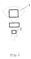
- Fig.1 a prior art antenna system is shown.
- the vertically (90°) placed antenna (2) creates a beam (1) with a beam-width of 90°.
- two antennas operating in phase can be coupled as shown in the prior art antenna system of Fig.2.
- Two vertically (90°) placed sector antennas (4,5) operating in phase are coupled via a coupler (6) to create a beam (3) with half the original beam-width, i.e. a beam-width of 45°.
- the gain is increased by 3dB, but the antenna system is two times larger compared to the antenna system of Fig.1.
- the invention uses only two antennas to form two small beams (i.e. two small sectors) at the same time.
- the antennas are connected by passive electronic elements, like couplers and cables.
- the advantage is that 2 antennas are saved, while the same effect is achieved.
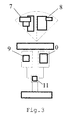
- Fig.3 an example of an antenna system according to the present invention is shown.
- Two beams (7,8), each with a beam-width of 45°, are created using two sector antennas (9,10).
- the two sector antennas can be placed in any direction. It is e.g. possible to place the antennas at +45° or at -45° or horizontally at 0° or vertically at 90°. In this example the two antennas are placed horizontally.
- the first beam (7) is shifted -45° and the second beam (8) is shifted +45°.
- the coupler (11) enabling this is shown in more detail in Fig.4.
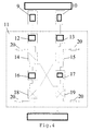
- Fig.4 two sector antennas (9,10) are coupled via coupler (11). A different phase is applied per antenna.
- the first antenna (9) is coupled to the first receiver pre-amplifier (12) and the second antenna (10) is coupled to the second receiver pre-amplifier.
- the hybrid couplers (14,15,18,19) and the phase shifters (16,17) create the different phases in which the antennas are operating.
- the antennas are receiving signals, half the signaling power is consumed by the resistors (20).
- the receiver pre-amplifiers (12,13) compensate the power loss.
- the antennas are transmitting signals
- half the signaling power is consumes by the resistors (20). This can be compensated by increasing the transmitting power by using X-Pol antennas or using air-combining.
- the invention makes it possible to build larger antenna systems to save more antennas and build very small sectors.
- Combining six or more antennas in e.g. a cylindrical line-up can result in small beams forming sectors with coverage of up to an angle of 360°.
- an example antenna system (21) is shown from above that can cover an angle of 360°.
- This antenna system comprises antennas (22) that are placed in a circle with a diameter (23).
- E.g. 36 sectors can be created using the invention, each sector being covered by an antenna creating a beam with a beam-width of 10.
Landscapes
- Engineering & Computer Science (AREA)
- Computer Networks & Wireless Communication (AREA)
- Variable-Direction Aerials And Aerial Arrays (AREA)
Applications Claiming Priority (2)
| Application Number | Priority Date | Filing Date | Title |
|---|---|---|---|
| US48763103P | 2003-07-16 | 2003-07-16 | |
| US487631 | 2003-07-16 |
Publications (1)
| Publication Number | Publication Date |
|---|---|
| EP1498986A1 true EP1498986A1 (fr) | 2005-01-19 |
Family
ID=34135081
Family Applications (1)
| Application Number | Title | Priority Date | Filing Date |
|---|---|---|---|
| EP04077070A Withdrawn EP1498986A1 (fr) | 2003-07-16 | 2004-07-16 | Système d'antenne pour la génération et l'utilisation de plusieurs faisceaux étroits à partir de plusieurs antennes à faisceaux larges |
Country Status (2)
| Country | Link |
|---|---|
| US (1) | US7280084B2 (fr) |
| EP (1) | EP1498986A1 (fr) |
Cited By (1)
| Publication number | Priority date | Publication date | Assignee | Title |
|---|---|---|---|---|
| WO2012140586A1 (fr) * | 2011-04-12 | 2012-10-18 | Vodafone Ip Licensing Limited | Antenne omnidirectionnelle ayant un point zéro dans une direction sélectionnée |
Families Citing this family (4)
| Publication number | Priority date | Publication date | Assignee | Title |
|---|---|---|---|---|
| US7075485B2 (en) * | 2003-11-24 | 2006-07-11 | Hong Kong Applied Science And Technology Research Institute Co., Ltd. | Low cost multi-beam, multi-band and multi-diversity antenna systems and methods for wireless communications |
| US8912957B2 (en) | 2011-12-12 | 2014-12-16 | Qualcomm Incorporated | Reconfigurable millimeter wave multibeam antenna array |
| US10171126B2 (en) * | 2015-08-31 | 2019-01-01 | Intel IP Corporation | Apparatus for uplink multi-antenna communication based on a hybrid coupler and a tunable phase shifter |
| CN114597641B (zh) * | 2022-02-28 | 2023-07-14 | 安徽大学 | 一种基于函数逼近理论的扇形波束天线单元 |
Citations (2)
| Publication number | Priority date | Publication date | Assignee | Title |
|---|---|---|---|---|
| US6218987B1 (en) * | 1997-05-07 | 2001-04-17 | Telefonaktiebolaget Lm Ericsson (Publ) | Radio antenna system |
| WO2001089030A1 (fr) * | 2000-05-18 | 2001-11-22 | Nokia Corporation | Reseau d'antennes hybrides |
Family Cites Families (7)
| Publication number | Priority date | Publication date | Assignee | Title |
|---|---|---|---|---|
| US4799065A (en) * | 1983-03-17 | 1989-01-17 | Hughes Aircraft Company | Reconfigurable beam antenna |
| US4499471A (en) * | 1983-05-02 | 1985-02-12 | Ford Aerospace & Communications Corporation | Reconfigurable dual mode network |
| JP2000244224A (ja) * | 1999-02-22 | 2000-09-08 | Denso Corp | マルチビームアンテナ及びアンテナシステム |
| GB9929375D0 (en) * | 1999-12-10 | 2000-02-09 | Nokia Networks Oy | An antenna system |
| US7283844B2 (en) * | 2000-04-04 | 2007-10-16 | Thompson Scott D | Multi-beam antenna wireless network system |
| SE517758C2 (sv) * | 2000-11-14 | 2002-07-09 | Ericsson Telefon Ab L M | Dubbelstråleantennapertur |
| US6922169B2 (en) * | 2003-02-14 | 2005-07-26 | Andrew Corporation | Antenna, base station and power coupler |
-
2004
- 2004-07-16 US US10/893,762 patent/US7280084B2/en not_active Expired - Fee Related
- 2004-07-16 EP EP04077070A patent/EP1498986A1/fr not_active Withdrawn
Patent Citations (2)
| Publication number | Priority date | Publication date | Assignee | Title |
|---|---|---|---|---|
| US6218987B1 (en) * | 1997-05-07 | 2001-04-17 | Telefonaktiebolaget Lm Ericsson (Publ) | Radio antenna system |
| WO2001089030A1 (fr) * | 2000-05-18 | 2001-11-22 | Nokia Corporation | Reseau d'antennes hybrides |
Non-Patent Citations (2)
| Title |
|---|
| DAU-CHYRH CHANG ET AL: "The study of butler matrix BFN for four beams antenna system", IEEE ANTENNAS AND PROPAGATION SOCIETY INTERNATIONAL SYMPOSIUM. 2003 DIGEST. APS. COLUMBUS, OH, JUNE 22 - 27, 2003, NEW YORK, NY : IEEE, US, vol. VOL. 4 OF 4, 22 June 2003 (2003-06-22), pages 176 - 179, XP010650930, ISBN: 0-7803-7846-6 * |
| GARY KWANG T K ET AL: "4X4 BUTLER MATRIX BEAM FORMING NETWORK USING NOVEL REDUCED SIZE BRANCHLINE COUPLER", 31ST EUROPEAN MICROWAVE CONFERENCE PROCEEDINGS. LONDON, SEPT. 25 - 27, 2001, PROCEEDINGS OF THE EUROPEAN MICROWAVE CONFERENCE, LONDON : CMP, GB, vol. VOL. 3 OF 3 CONF. 31, 25 September 2001 (2001-09-25), pages 137 - 140, XP001044927, ISBN: 0-86213-148-0 * |
Cited By (1)
| Publication number | Priority date | Publication date | Assignee | Title |
|---|---|---|---|---|
| WO2012140586A1 (fr) * | 2011-04-12 | 2012-10-18 | Vodafone Ip Licensing Limited | Antenne omnidirectionnelle ayant un point zéro dans une direction sélectionnée |
Also Published As
| Publication number | Publication date |
|---|---|
| US7280084B2 (en) | 2007-10-09 |
| US20050037813A1 (en) | 2005-02-17 |
Similar Documents
| Publication | Publication Date | Title |
|---|---|---|
| US12199715B2 (en) | Small cell beam-forming antennas | |
| CA2142583C (fr) | Antenne de station de base | |
| US9293809B2 (en) | Forty-five degree dual broad band base station antenna | |
| EP3686991B1 (fr) | Antennes omnidirectionnelles compactes dotées de structures de réflecteur empilées | |
| US20230170957A1 (en) | Small cell beamforming antennas suitable for use with 5g beamforming radios and related base stations | |
| US20100188289A1 (en) | Communication system and method using an active phased array antenna | |
| US11411301B2 (en) | Compact multiband feed for small cell base station antennas | |
| US20240047861A1 (en) | Small cell beamforming antennas suitable for use with 5g beamforming radios and related base stations | |
| KR200235289Y1 (ko) | 다 측방향 측대파 억압형 지향성 안테나 | |
| CN117220042A (zh) | 天线阵列及电子设备 | |
| US7280084B2 (en) | Antenna system for generating and utilizing several small beams from several wide-beam antennas | |
| US12294430B2 (en) | Signal processing device and base station antenna | |
| Derneryd et al. | Adaptive base-station antenna arrays | |
| EP3742553B1 (fr) | Antenne à polarisation verticale et dispositif terminal | |
| US20080200116A1 (en) | Multi Beam Repeater Antenna for Increased Coverage | |
| US20080102776A1 (en) | Antenna for a Radio Base Station in a Mobile Cellular Telephony Network |
Legal Events
| Date | Code | Title | Description |
|---|---|---|---|
| PUAI | Public reference made under article 153(3) epc to a published international application that has entered the european phase |
Free format text: ORIGINAL CODE: 0009012 |
|
| AK | Designated contracting states |
Kind code of ref document: A1 Designated state(s): AT BE BG CH CY CZ DE DK EE ES FI FR GB GR HU IE IT LI LU MC NL PL PT RO SE SI SK TR |
|
| AX | Request for extension of the european patent |
Extension state: AL HR LT LV MK |
|
| 17P | Request for examination filed |
Effective date: 20050719 |
|
| AKX | Designation fees paid |
Designated state(s): AT BE BG CH CY CZ DE DK EE ES FI FR GB GR HU IE IT LI LU MC NL PL PT RO SE SI SK TR |
|
| 17Q | First examination report despatched |
Effective date: 20070531 |
|
| STAA | Information on the status of an ep patent application or granted ep patent |
Free format text: STATUS: THE APPLICATION IS DEEMED TO BE WITHDRAWN |
|
| 18D | Application deemed to be withdrawn |
Effective date: 20071011 |