EP1499105A2 - Ausgabesystem, Steuervorrichtung, Extraktionsverfahren und Steuerprogramm für Bilddaten und Programmspeichermedium - Google Patents
Ausgabesystem, Steuervorrichtung, Extraktionsverfahren und Steuerprogramm für Bilddaten und Programmspeichermedium Download PDFInfo
- Publication number
- EP1499105A2 EP1499105A2 EP04016268A EP04016268A EP1499105A2 EP 1499105 A2 EP1499105 A2 EP 1499105A2 EP 04016268 A EP04016268 A EP 04016268A EP 04016268 A EP04016268 A EP 04016268A EP 1499105 A2 EP1499105 A2 EP 1499105A2
- Authority
- EP
- European Patent Office
- Prior art keywords
- image data
- image
- size
- section
- area
- Prior art date
- Legal status (The legal status is an assumption and is not a legal conclusion. Google has not performed a legal analysis and makes no representation as to the accuracy of the status listed.)
- Withdrawn
Links
Images


Classifications
-
- H—ELECTRICITY
- H04—ELECTRIC COMMUNICATION TECHNIQUE
- H04N—PICTORIAL COMMUNICATION, e.g. TELEVISION
- H04N1/00—Scanning, transmission or reproduction of documents or the like, e.g. facsimile transmission; Details thereof
- H04N1/387—Composing, repositioning or otherwise geometrically modifying originals
- H04N1/3872—Repositioning or masking
- H04N1/3873—Repositioning or masking defined only by a limited number of coordinate points or parameters, e.g. corners, centre; for trimming
Definitions
- This invention relates to an image output system, a control device, an image extracting method, a program to execute the method, and a storage medium that stores the program, and particularly to a means that outputs, as a color sample for correction, a large image that overflows an image output area of an image output device.
- DDCP Direct Digital Color Proof
- This DDCP system is to create a digital color proof (DCP) for confirmation of images, color tones, text characters, etc. before recording page-arranged image data on a make-up plate by an image setter, directly creating a plate by the CTP for final printing, and directly printing images on a plate wound on a cylinder.
- DCP digital color proof
- the DCP creating system Before creating a DCP, the DCP creating system outputs small images of single image pages (image data before page arrangement) to a color laser printer for confirmation of images, color tones, text characters, etc. of the resulting color comprehensive image layout.
- Such color laser printers can be represented by an electrophotographic color laser printer disclosed by Japanese Patent Publication H05-48857 (Paragraphs 0011 to 0070 and FIG. 1 to FIG. 13) and a complex machine having scanner, copier, and facsimile functions.
- image data to be used for color correction is the same as the image data to be output to the CTP or the like for final printing.
- This kind of image data is digital data (file) obtained by analyzing and processing the page-arranged image data (image data described by PDF or PostScript which is a general page description language) by the raster image processor (RIP) connected to the CTP (by raster- or outline-processing vector data such as character font information).
- the data is shared by the CTP and the DCP to shorten the RIP processing time and eliminate output differences due to RIP differences.
- image data output by the CTP is image data of the standard size or greater (e.g. A1 wide size of 670 mm long ⁇ 967 mm wide) which lays out some image data pages (e.g. 8 pages) of a small size (e.g. A4 size of 297 mm long ⁇ 210 mm wide) with margins (a register mark area and a punched area for the CTP plate).
- image data pages e.g. 8 pages
- margins a register mark area and a punched area for the CTP plate.
- almost all current color laser printers output to at most A3-wide size sheets (457 mm long ⁇ 311 mm wide) and they are hard to properly output image data of greater than the standard size. In such cases, for reference's sake, part of the image data output by the CTP is output by the output sizes of the color laser printer.
- image data of two A4-size pages (297 mm long ⁇ 210 mm wide) is output using a recording medium of the A3-size (297 mm long ⁇ 420 mm wide) or when image data of the A4-size (297 mm long ⁇ 210 mm wide) is output using a recording medium of the A4-size (297 mm long ⁇ 210 mm wide), the image data by the CTP cannot be output properly because of margins.
- Japanese Non-examined Patent Publication H05-153363 discloses an image-information processing device or the like as the basic concept.
- An object of this invention is to provide an image output system that extracts and outputs a proper area when outputting page-arranged image data that overflows a recording medium as a color sample for calibration, a control device, an image extracting method, a program to execute the method, and a storage medium that stores the program.
- this invention provides an image output system comprising a control device to receive image data that lays out one or more smaller image pages and to send image data extracted from a specific area that encloses said image pages and an image output device that outputs images according to said sent and extracted image data; wherein said control device further comprises an image data storing section that stores said received image data, an image data analyzing section that analyzes the size of an image of said stored image data, an image area memorizing section that memorizes the size of image area that is output by the image output device according to the size of each storing medium, a medium specifying section that specifies the size of a recording medium that is output by said image output device, a comparing and determining section that compares the size of said analyzed image with that of an image area corresponding to said specified recording medium that is stored in said image area memorizing section and determines an extraction area that encloses an image of said stored image data, and an extracting section that extracts a relevant image data from said stored image data into said extraction area according to said determined extraction
- a control device for an image output device that outputs images according to image data receives image data that lays out one or more smaller image pages from an external device and sends image data extracted from a specific area that encloses said image pages.
- Said control device further comprises an image output device that outputs images according to said sent and extracted image data; wherein said control device further comprises an image data storing section that stores said received image data, an image data analyzing section that analyzes the size of an image of said stored image data, an image area memorizing section that memorizes the size of image area that is output by the image output device according to the size of each storing medium, a medium specifying section that specifies the size of a recording medium that is output by said image output device, a comparing and determining section that compares the size of said analyzed image with that of an image area corresponding to said specified recording medium that is stored in said image area memorizing section and determines an extraction area that encloses an image of said stored image data, and an extracting section that extracts a relevant image data from said stored image
- An image data extracting method comprising steps of receiving image data that lays out one or more smaller image pages from an external device, creating image data extracted from a specific area that encloses said image pages, and outputting images according to the extracted image data; wherein said method further comprises a step of storing said received image data, a step of analyzing the size of an image of said stored image data, a step of memorizing the size of image area that is output by the image output device according to the size of each storing medium a step of specifying the size of a recording medium that is output by said image output device, a step of comparing the size of said analyzed image with that of an image area corresponding to said specified recording medium that is stored in said image area memorizing section and determining an extraction area that encloses an image of said stored image data, and a step of extracting a relevant image data from said stored image data into said extraction area according to said determined extraction area and creating image data extracted from said specific area.
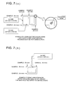
- the image output system consists of a client terminal 1 that performs image edition of image data and page arrangement (imposition or layout for printing format), a controller 2 that receives image data for color comprehensive layout (image data of a single page before page arrangement) that is written, for example, by PostScript from the client terminal 1 and sends the image data to a color laser printer 3 to be explained later, a color laser printer 3 of the charged duplication type that receives the image data for color comprehensive layout from the controller 2 and outputs an image based on the image data or receives image data for final output (image arranging pages of the image data for color comprehensive layout) from the RIP 4 for CTP (to be explained later) and outputs an image based on the image data, an RIP 4 for CTP that receives image data for final output that is written, for example, by PostScript from the client terminal 1, performs RIP processing (converting the image data into bit map data according to the output resolution of the CTP 6 and the DCP creator), and sends the image data to the controller, the CTP 6,
- the client terminal 1, the controller 2, the RIP 4 for CTP, and the DCP controller 5 respectively work as a computer terminal.
- Each computer terminal is equipped with a keyboard, a monitor, and so on. Some required operation programs are preinstalled in the computer.
- the client terminal 1 is equipped with an image input means such as an image scanner to get image data.
- the client terminal 1 edits and sends image data to the controller 2.
- the controller 2 controls the color laser printer 3 to output a color comprehensive layout (S01).
- the "color comprehensive layout” means a colored finishing sample that is almost the final printout containing dummy layouts of pictures and illustrations. This sample can be used to check whether the image design satisfies the client's plan and intention of edition and to get an approval from the client.
- the "color comprehensive layout” is a small-scale printout of single pages and will be approved after proofing and the like.
- the client terminal 1 When the "color comprehensive layout" is found acceptable by the operator (Yes at S02), the client terminal 1 performs page arrangement on the color comprehensive layout.
- SO3 "Page arrangement” also termed “imposition” or “layout for printing format” means to lay out images such as pictures and illustrations by 16, 8, or 4 pages according to the size of the print sheet so that they may be arranged in the order of folios (page numbers respectively given to each page end) when a plating film is printed into a final signature.
- the RIP 4 for CTP When receiving page-arranged image data for final output from the client terminal 1, the RIP 4 for CTP performs raster image processing (RIP) on the image data, that is, converts the image data into bit map data according to the output resolution of the DCP creator 7 or CTP 6 (SO4).
- the RIP 4 for CTP sends this RIPed image data to the controller 2.
- the controller 2 controls the color laser printer 3 to output images of the final image data (S05).
- the page-arranged image printout is used as a DCP (digital color proof).
- the RIPed image data is sent to the DCP controller 7.
- the DCP controller 7 controls the DCP creator 8 to output images of the final output image data.
- the page-arranged image printout is used as a DCP.
- the DCP is color-checked.
- the RIP for CTP sends the RIPed image data (the same image data that was used to output the DCP) to the CTP.
- the CTP directly records the image on the print plate (S07). Then, printing is made by the print plate and the page-arranged printout is color-corrected. When the printout is found acceptable by the operator (Yes at SO8), the final printout is made by a printer. (S09).
- controller 2 constituting the image output system of this embodiment
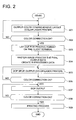
- the configuration and outline operations of the controller 2 constituting the image output system of this embodiment will be explained with reference to FIG. 3 and FIG. 5 along a flow of a flowchart in FIG. 4.
- the description below mainly explains output processing of page-arranged image data by the controller 2 which is characterized by this invention.
- the controller 2 consists of an image data storing section 20 that receives and stores the entered image data, an image data input monitoring section 21 that monitors how the image data is stored in the image data storing section 20, an image data analyzing section 22 that receives a notification from the image data input monitoring section 21 and analyzes the image size of the image data stored in the image data storing section 20, a medium specifying section 23 that specifies the size of recording medium to which the image data is output from the image data storing section 20, an image area memorizing section 24 that memorizes sizes of image output areas of the color laser printer 3 according to the sizes of the memory media in advance, a size comparing section 25 that determines a trim area (to be cut out) of an image whose size is analyzed by the image data analyzing section 22 before the image is output to a recording medium of a size specified by the medium specifying section 23 according to the size of an image output area of a relevant recording medium (recording medium of a size specified by the medium specifying section 23) that is memorized in the
- the input monitoring section 21 gives a notice to the image data analyzing section 22.
- the image data analyzing section 22 analyzes the image size of the image data that is stored in the image data storing section 20 (an image data analyzing step). This section gets the image size (N mm long by M mm wide), coordinates, and page arrangement information (Number of pages in row and number of pages in column in the relevant image data) that is described in the relevant image data. (S11).
- the image data analyzing section 22 gets, as the image size of the relevant image data, the total size of the arranged image data areas excluding the marginal areas (the register mark area and the punch area of the CTP plate). Namely, Such a case assumes that the sizes of the marginal area and the page-arranged areas are described in the image data.
- the monitor unit of the controller 2 displays the above-described page-arrangement information by means of GUI (graphical user interface)(a displaying step).
- GUI graphical user interface
- the operator specifies a proper size of a recording medium to which image data is output from the image data storing section 20 on the medium specifying section 23.
- the operator specifies a size of a recording medium to which all areas that enclose the image of the page-arranged image data is output.
- the size of an image data output medium is obtained.
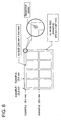
- the size comparing section 25 reads an image output area corresponding to a recording medium size specified by the medium specifying section 23 from image output areas of the color laser printer 3 corresponding to recording medium sizes that are stored in the image area memorizing section 24 in advance (an image area storing step) (S13). Then the size comparing section 25 determines a trimmed area of the image of the image size analyzed by the image data analyzing section 22 according to the size of the image data analyzing section 22 (V mm long by H mm wide) when the image is output to a recording medium of a size specified by the medium specifying section 23 (a comparing and determining step).
- the size comparing section 25 compares the image size (N mm long by M mm wide) of the image data stored in the image data storing section 20 with the image output area (V mm long by H mm wide) corresponding to the recording medium specified by the medium specifying section 23 and judges whether the image size of the image data exceeds the size of the image output area (in length, width, or both). (S14) When the image size of the image data does not exceed the size of the image output area (No at S14), the trimming section 26 reads image data line by line from the image data storing section 20 and outputs the image data to the screen processing section 27 without carrying out trimming (to be explained later).
- the screen processing section 27 receives each line of the image data from the trimming section 26, performs color adjustment and screen processing on each line of the image data and sends it to the color laser printer 3. If the length or width of the image data exceeds that of the image output area (Yes at S14), the trimming section 26 calculates the coordinates of a trimming origin (X, Y) (see FIG. 5) by Equation 1. As already explained, this assumes that the positional coordinates of the image of the image data are described in the image data.
- the image data analyzing section 22 analyzes the positional coordinates.
- the size comparing section 25 selects and reads the relevant positional coordinates of the image output area corresponding to the recording medium specified by the medium specifying section 23 from those stored together with the image output areas of the color laser printer 3 corresponding to sizes of recording media in the image area memorizing section 24.
- this embodiment places the origin of the coordinates at the lower left corner of the image of the image data.
- the trimming section 26 reads the image data line by line from the image data storing section (S16) and checks whether the coordinates (x, y) of the first pixel of each line satisfy all of the conditions below (S17). [Equation 2] x > X x ⁇ (X + H) y > Y y ⁇ (Y + V)
- the screen processing section 27 goes to step S19 without performing any color adjustment and screen processing on data corresponding to the pixel.
- the screen processing section 27 performs a color adjustment and screen processing on data corresponding to the pixel (S18).
- the trimming section 26 When the image data is to be output by the CTP, the trimming section 26 performs the above trimming on the area of the page-arranged image data excluding a marginal area (register mark and a punched area of the CTP plate) that need not be output.
- the color laser printer 3 Upon receiving the image data, the color laser printer 3 prints out images of the image data (S22).
- the operator uses the printout on the color laser printer 3 as the DCP.
- the operator can specify a proper size of an output recording medium and use the printout as the DCP because the image output system causes the trimming section 26 to extract a proper area and trim its periphery and the color laser printer 3 to output the extracted area.
- the controller 2 in the image output system performs trimming operations, particularly, processing at steps S10 to S21 in the flow chart (FIG. 4) by programs. These programs are stored in the controller 2 or a recording medium connected to the controller and read and run by the operation part in the controller 2.
- the storage medium can be any selected from a set of semiconductor memory (such as ROM, RAM, and flash memory), memory devices (such as integrated circuits), optical disks, magnetic optical disks (CD-ROM, DVD-RAM, DVD-ROM, and MO), magnetic storage media ⁇ magnetic disk> (hard disks, floppy TM disks, and ZIP) and so on.
- semiconductor memory such as ROM, RAM, and flash memory
- memory devices such as integrated circuits
- optical disks such as CD-ROM, DVD-RAM, DVD-ROM, and MO
- magnetic storage media ⁇ magnetic disk> hard disks, floppy TM disks, and ZIP
- the image output system, the controller, the image extracting method, programs to execute the method, and the storage medium that stores the programs in this embodiment are included merely to aid in the understanding of the invention and it is to be understood that the invention is not intended to be limited to the specific embodiments.
- this embodiment gets the size of a recording medium which outputs image data when the operator specifies the size by the medium specifying section. It is also possible to get the size of a recording medium by automatically selecting the maximum size among those installed in the color laser printer 3 or by automatically selecting a default size among those installed in the color laser printer 3.
- the controller in accordance with the image output system, the controller, the image extracting method, the program to execute the method, and the storage medium that stores the program of this invention, even when outputting page-arranged image data which overflows a recording medium, the operator can specify a proper size of an output recording medium and use the printout as the DCP because the image output system causes the trimming section to extract a proper area and trim its periphery and the color laser printer to output the extracted area.
- the device cost can be reduced greatly as a color laser printer that is low in the device and running costs and can print out fast can be used actually as a means to create a DCP.
- the controller when the image data is to be output by the CTP, only the area of the page-arranged image data excluding a marginal area (register mark and a punched area of the CTP plate) that need not be output is trimmed and output. Therefore, also in such a case, a proper area is output by the color laser printer and the operator can preferably use the printout as the DCP.
- the above effect can be obtained without increasing the device cost as the above effect can be actualized by general computer software.
Landscapes
- Engineering & Computer Science (AREA)
- Multimedia (AREA)
- Signal Processing (AREA)
- Editing Of Facsimile Originals (AREA)
- Record Information Processing For Printing (AREA)
- Processing Or Creating Images (AREA)
- Image Analysis (AREA)
Applications Claiming Priority (2)
| Application Number | Priority Date | Filing Date | Title |
|---|---|---|---|
| JP2003197071A JP2005037993A (ja) | 2003-07-15 | 2003-07-15 | 画像出力システム、制御装置、画像抽出方法、その方法を実行させるためのプログラム、及び、そのプログラムを記憶した記憶媒体 |
| JP2003197071 | 2003-07-15 |
Publications (2)
| Publication Number | Publication Date |
|---|---|
| EP1499105A2 true EP1499105A2 (de) | 2005-01-19 |
| EP1499105A3 EP1499105A3 (de) | 2006-06-07 |
Family
ID=33475492
Family Applications (1)
| Application Number | Title | Priority Date | Filing Date |
|---|---|---|---|
| EP04016268A Withdrawn EP1499105A3 (de) | 2003-07-15 | 2004-07-09 | Ausgabesystem, Steuervorrichtung, Extraktionsverfahren und Steuerprogramm für Bilddaten und Programmspeichermedium |
Country Status (3)
| Country | Link |
|---|---|
| US (1) | US20050012962A1 (de) |
| EP (1) | EP1499105A3 (de) |
| JP (1) | JP2005037993A (de) |
Families Citing this family (5)
| Publication number | Priority date | Publication date | Assignee | Title |
|---|---|---|---|---|
| CN100349159C (zh) * | 2005-01-18 | 2007-11-14 | 北京北大方正电子有限公司 | 一种在页面光栅化时刻附加标记的方法 |
| JP4938556B2 (ja) | 2007-06-11 | 2012-05-23 | 富士フイルム株式会社 | 画像配置装置および画像配置プログラム |
| US8516365B2 (en) * | 2007-06-15 | 2013-08-20 | Microsoft Corporation | Dynamically laying out images and associated text using pre-defined layouts |
| US20110221764A1 (en) * | 2010-03-12 | 2011-09-15 | Microsoft Corporation | Laying out and cropping images in pre-defined layouts |
| JP6272061B2 (ja) * | 2014-01-31 | 2018-01-31 | キヤノン株式会社 | 画像形成装置、その制御方法、及びプログラム |
Family Cites Families (6)
| Publication number | Priority date | Publication date | Assignee | Title |
|---|---|---|---|---|
| JPS5974558A (ja) * | 1982-10-21 | 1984-04-27 | Dainippon Screen Mfg Co Ltd | 複製画像のレイアウト記録方法 |
| US5115320A (en) * | 1989-09-20 | 1992-05-19 | Olympus Optical Co., Ltd. | Apparatus for editing and printing a video image |
| JPH05153363A (ja) * | 1991-11-28 | 1993-06-18 | Sanyo Electric Co Ltd | 画像情報処理装置 |
| JP3206060B2 (ja) * | 1991-12-26 | 2001-09-04 | ミノルタ株式会社 | 画像編集装置 |
| US7068391B2 (en) * | 2000-03-08 | 2006-06-27 | Barco Graphics, Nv | Proofing method, apparatus, and computer software product matching color and halftone screen properties |
| JP2003046790A (ja) * | 2001-07-30 | 2003-02-14 | Fuji Photo Film Co Ltd | 色修正指示装置 |
-
2003
- 2003-07-15 JP JP2003197071A patent/JP2005037993A/ja active Pending
-
2004
- 2004-07-07 US US10/886,430 patent/US20050012962A1/en not_active Abandoned
- 2004-07-09 EP EP04016268A patent/EP1499105A3/de not_active Withdrawn
Also Published As
| Publication number | Publication date |
|---|---|
| EP1499105A3 (de) | 2006-06-07 |
| JP2005037993A (ja) | 2005-02-10 |
| US20050012962A1 (en) | 2005-01-20 |
Similar Documents
| Publication | Publication Date | Title |
|---|---|---|
| US7268910B2 (en) | Just-in-time raster image assembly | |
| JP3962313B2 (ja) | 印刷製版における検版 | |
| US7339695B2 (en) | Data processing device, data processing method, and data processing program for recognizing characters in a URL | |
| US8373888B2 (en) | Printer driver program and image forming apparatus | |
| EP1783999A2 (de) | Bildverarbeitungsvorrichtung und Computerprogrammprodukt | |
| US8384946B2 (en) | Image forming apparatus, method, and computer product for positioning images of different size on a given paper size | |
| US20030007167A1 (en) | Seamless multi-page spreads | |
| JP2002165079A (ja) | 画像処理装置及び方法 | |
| US8199967B2 (en) | Image processing apparatus, image processing method, and storage medium | |
| US7933447B2 (en) | Image processing apparatus and method thereof | |
| EP1764739B1 (de) | Bildverarbeitungsvorrichtung und Computerprogrammprodukt | |
| EP1499105A2 (de) | Ausgabesystem, Steuervorrichtung, Extraktionsverfahren und Steuerprogramm für Bilddaten und Programmspeichermedium | |
| US20060197964A1 (en) | Printing system for operating marginless printing on roll paper | |
| EP1385119A2 (de) | Bildverarbeitungsgerät und Bildverarbeitungsprogrammspeichermedium | |
| EP1509036A2 (de) | Bilderzeugungssystem | |
| US7317552B2 (en) | Print data forming apparatus, print data forming method, and computer-readable program | |
| US20120254741A1 (en) | Proofreading apparatus, proofreading method, and recording medium | |
| US8352860B2 (en) | Image processing device and method for notifying a user of an included compressed image | |
| EP1511292A2 (de) | Bildausgabesystem | |
| JP2005056285A (ja) | 画像出力システム、画像出力制御方法、その方法を実行するためのプログラム及びプログラムを格納した記録媒体 | |
| US20240177266A1 (en) | Image processing apparatus, image forming apparatus, image processing method, and storage medium | |
| JP2005063347A (ja) | 画像出力システム、制御装置、画像分割方法、その方法を実行させるためのプログラム、及び、そのプログラムを記憶した記憶媒体 | |
| JP2005057466A (ja) | 画像出力システム、制御装置、画像分割方法、その方法を実行させるためのプログラム、及び、そのプログラムを記憶した記憶媒体 | |
| JP2000184176A (ja) | 画像処理装置、画像処理方法およびその方法をコンピュータに実行させるプログラムを記録したコンピュータ読み取り可能な記録媒体 | |
| JP2006121552A (ja) | 画像出力システム、画像出力方法、その方法を実行させるためのプログラム、及び、そのプログラムを記憶した記憶媒体 |
Legal Events
| Date | Code | Title | Description |
|---|---|---|---|
| PUAI | Public reference made under article 153(3) epc to a published international application that has entered the european phase |
Free format text: ORIGINAL CODE: 0009012 |
|
| AK | Designated contracting states |
Kind code of ref document: A2 Designated state(s): AT BE BG CH CY CZ DE DK EE ES FI FR GB GR HU IE IT LI LU MC NL PL PT RO SE SI SK TR |
|
| AX | Request for extension of the european patent |
Extension state: AL HR LT LV MK |
|
| PUAL | Search report despatched |
Free format text: ORIGINAL CODE: 0009013 |
|
| AK | Designated contracting states |
Kind code of ref document: A3 Designated state(s): AT BE BG CH CY CZ DE DK EE ES FI FR GB GR HU IE IT LI LU MC NL PL PT RO SE SI SK TR |
|
| AX | Request for extension of the european patent |
Extension state: AL HR LT LV MK |
|
| RIC1 | Information provided on ipc code assigned before grant |
Ipc: H04N 1/60 20060101ALI20060425BHEP Ipc: H04N 1/387 20060101AFI20041029BHEP |
|
| AKX | Designation fees paid | ||
| STAA | Information on the status of an ep patent application or granted ep patent |
Free format text: STATUS: THE APPLICATION IS DEEMED TO BE WITHDRAWN |
|
| 18D | Application deemed to be withdrawn |
Effective date: 20070201 |
|
| REG | Reference to a national code |
Ref country code: DE Ref legal event code: 8566 |