EP1499772B1 - Automatische dosiervorrichtung und ihre verwendung - Google Patents
Automatische dosiervorrichtung und ihre verwendung Download PDFInfo
- Publication number
- EP1499772B1 EP1499772B1 EP03710596A EP03710596A EP1499772B1 EP 1499772 B1 EP1499772 B1 EP 1499772B1 EP 03710596 A EP03710596 A EP 03710596A EP 03710596 A EP03710596 A EP 03710596A EP 1499772 B1 EP1499772 B1 EP 1499772B1
- Authority
- EP
- European Patent Office
- Prior art keywords
- container
- dosing device
- automatic dosing
- machine
- detergent
- Prior art date
- Legal status (The legal status is an assumption and is not a legal conclusion. Google has not performed a legal analysis and makes no representation as to the accuracy of the status listed.)
- Expired - Lifetime
Links
Images


Classifications
-
- G—PHYSICS
- G01—MEASURING; TESTING
- G01F—MEASURING VOLUME, VOLUME FLOW, MASS FLOW OR LIQUID LEVEL; METERING BY VOLUME
- G01F13/00—Apparatus for measuring by volume and delivering fluids or fluent solid materials, not provided for in the preceding groups
- G01F13/001—Apparatus for measuring by volume and delivering fluids or fluent solid materials, not provided for in the preceding groups for fluent solid material
- G01F13/005—Apparatus for measuring by volume and delivering fluids or fluent solid materials, not provided for in the preceding groups for fluent solid material comprising a screw conveyor
-
- D—TEXTILES; PAPER
- D06—TREATMENT OF TEXTILES OR THE LIKE; LAUNDERING; FLEXIBLE MATERIALS NOT OTHERWISE PROVIDED FOR
- D06F—LAUNDERING, DRYING, IRONING, PRESSING OR FOLDING TEXTILE ARTICLES
- D06F33/00—Control of operations performed in washing machines or washer-dryers
- D06F33/30—Control of washing machines characterised by the purpose or target of the control
- D06F33/32—Control of operational steps, e.g. optimisation or improvement of operational steps depending on the condition of the laundry
- D06F33/37—Control of operational steps, e.g. optimisation or improvement of operational steps depending on the condition of the laundry of metering of detergents or additives
-
- D—TEXTILES; PAPER
- D06—TREATMENT OF TEXTILES OR THE LIKE; LAUNDERING; FLEXIBLE MATERIALS NOT OTHERWISE PROVIDED FOR
- D06F—LAUNDERING, DRYING, IRONING, PRESSING OR FOLDING TEXTILE ARTICLES
- D06F39/00—Details of washing machines not specific to a single type of machines covered by groups D06F9/00 - D06F27/00
- D06F39/02—Devices for adding soap or other washing agents
- D06F39/026—Devices for adding soap or other washing agents the powder or tablets being added directly, e.g. without the need of a flushing liquid
Definitions
- the present invention refers to an automatic dosing device.
- the purpose of the device is to store and dose material, kept inside a container part, and to make it possible for an operator to refill the container with material.
- the automatic dosing device therefore comprises a refilling container, a dosing screw, a control system, a driving motor and a guiding mechanism.
- the container stores the material, the screw doses it out of the container, the system controls the dosing and the mechanism guides the container between an inner position where the device can dose material and an outer position where an operator is allowed to refill it with material.
- US 5063757 proposes a detergent dispenser with this kind of dosing and closing mechanism.
- the dispenser includes a detergent container with a lower discharge outlet from which stored detergent is discharged and a detergent fall preventing member displaced in the outlet in order to close the outlet when detergent is not dosed.
- the dosing is achieved by a helical coil/screw arranged is a discharge passageway.
- An agitating member is disposed in the detergent container in order to avoid clogging of the detergent.
- the helical coil or screw and the agitating member are rotated by an electric motor mounted together with the container.
- the container, with an outer and inner casing, is detachably mounted to the machine by claws.
- US 4207995 discloses another dispensing device.
- a canister is provided with a screw for dispensing granular material.
- An agitator inside the canister has teeth to cooperate with the screw flights of the screw.
- the dispensing device as shown in fig. 1 is designed for free-standing and not for integration into a b.
- a motor 36 drives the screw via a driver 34 in order to dispense material through the opening at the spout 38.
- the present invention has been made with a view toward overcoming the above drawbacks of the prior art.
- the first object of the present invention is therefore to provide an automatic dosing device as a detergent dispenser that is easy to integrate in a proper way in a machine and easy to handle by an operator. In order to achieve that the device has means for exposing the container when necessary and hide it when not.
- a second object of the present invention is to provide a device that doses more or less automatically. In order to achieve that the device has a control unit and possibilities to read in information from which the device is controlled.
- a third object of the present invention is to achieve a cheap device that is simple to manufacture. In order to achieve that the device has few simple parts in cheap, reliable material.
- the device is mainly designed for a laundry washing machine but the principle idea shall be applicable for any kind of machine which requires an automatic dosing device.
- the solution of this present invention is achieved according to the features disclosed in claim 1.
- an automatic dosing device for storing and automatically dosing stored material into a process is achieved.
- the device has a refill container, a dosing screw, a driving motor, a control system and a guiding mechanism.
- the container stores the material, the screw doses it out of the container, the system controls the dosing and the mechanism guides the container between an inner position where the device can dose material and an outer position where an operator is allowed to refill it with material.
- the automatic dosing device is a dosing device for laundry washing machines, whereby any reference concerning dosing material refers to detergent.
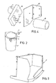
- the dosing device has a container part 1, which comprises a receptacle 2 in which the detergent is stored and a cover 3.
- a handle 4 serves as a locking means for the cover.
- One end of a dosing screw 5 extends out of the receptacle and has two wings 6 whose function will be described below.
- the device comprises a mixer 7, which at its backside has a motor opening 8 and a guiding opening 18. The function of the mixer and the container is explained further below.
- a motor opening 8 guides a motor part, see fig. 4.
- the motor part has an electric motor 9 with a gear 10.
- a motor shaft 11 transmits the rotation from the motor to a clutch 13.
- the clutch is attached to the shaft so as to rotate together with it.
- a motor bracket 12 that supports the motor pieces is fixed to a guidance frame 14. The function of the motor part is described further below.
- the guiding mechanism comprises the guiding frame 14 and a guiding shaft 15.
- the shaft see fig. 6, has a flat iron piece 16 and a container support 17 attached at one end.
- the shaft stretches through the guiding opening 18 and the support is attached or detachably attached to the container 1.
- the frame 14 is U-shaped and comprises an opening 19.
- a front 20 is a part of the laundry washing machine in which the automatic dosing device is applied. The function of the guiding parts is described further below.
- An object of this system is to get information about the level of detergent inside the container part 1, in order to indicate when it is time to refill the container and when the container is empty.
- a first and simple way is to detect the level through a transparent part of the receptacle 2 or the cover 3.
- a second way is to use a photo detector with a transmitter of light and an optical sensor as a receiver of light.
- the transmitter could be arranged in different ways.
- a first arrangement is to place them on each side of a cavity created inside the container part, the cavity being placed at the lowest point of the container part. When there is no longer detergent between the transmitter and the receiver, which corresponds to a low detergent level inside the container, the light reaches the receiver and the system indicates the low detergent level.
- a second arrangement is to place a mirror inside the detergent container that reflects the transmitted light towards the receiver. When the detergent reaches a certain lower level the reflected light reaches the receiver and the system indicates a low detergent level. The mirror is placed in a proper way as to achieve the best detecting result of the detergent level.
- a third arrangement is to detect if detergent comes out from the container part.
- the transmitter and receiver are placed at the outlet of the container part and when there is no or little detergent in the outlet the receiver detects the system indicates a low detergent level or problems with the feeding to the outlet.
- a forth way is to use a sensor that detects the motion of a moving part arranged to slide inside the container part.
- the moving part When there is a lot of detergent the moving part is forced in a first direction by the detergent.
- the detergent level goes down the moving part moves with the level towards the sensor.
- the sensor is thereby affected and thus detects a signal or similar which corresponds to the amount of detergent left.
- the sensor could be a Hall effect sensor detecting magnetic fields from the moving part that includes a magnetic piece.
- the moving part could be equipped with a flange or similar in order to float and move with the detergent surface.
- the device according to the preferred embodiment is also intended to work with a control system, whereby the function of this system also is described.
- the aim of the dosing device is to attain a device that solves the above mentioned objects. That is a device, which is easy to refill and work with and that is cheap with few parts and simple to manufacture.
- the guiding mechanism 14-16 and 19 has as a task to guide the container part 1 between an outer position away from the mixer 7 and an inner position inside the mixer, not shown. In its outer position the flat iron piece 16 is in a position pointing out through the opening 19, see fig. 1. This makes it possible to turn the container part and its front into the upright position shown in fig. 1. Is this position the container cover 3 can be opened and detergent filled into the receptacle 2.
- the cover 3 is closed and locked by the handle 4.
- the operator thereafter turns the container part 1 in an anti-clockwise direction (seen from the left side in fig. 1) until the iron piece 16 hits the inner wall of the guiding frame 14.
- the operator then moves the horizontal container part towards the mixer 7, guided by the guiding mechanism.
- the conical shaped container part is finally guided into the inner position inside the mixer.
- the dosing screw end moves towards the motor opening 8, in which the clutch 13 is positioned.
- the wings 6 and the clutch 13 design (not shown) co-operates to guide the screw 5 into turning engagement with the shaft 11.
- the motor 9 is thereby in turning engagement with the dosing screw 5.
- the front 20 as a part of the washing machine finally keeps the container in its inner position.
- the motor rotates whenever detergent needs to be dispensed out of the container part by the screw.
- the control system detects if there is enough detergent in the container part 1, see above. If there is enough detergent the screw doses detergent out to the mixer 7.
- the mixer also comprises a water inlet (not shown), which fills water into the mixer a little while before detergent is dosed, during the dosing and a little while afterwards. The water and detergent are mixed inside the mixer and flows further towards the washing tub.
- the control system needs some information in order to control the washing and dosing and achieve a right detergent concentration.
- the object of this system is therefore to get information about the amount of laundry, water and the washing program and by means of these parameters achieve the right detergent concentration.
- a first solution is to use an interface by which the operator can program at least some of this information. This is a normal procedure and it does not need any special efforts from the operator. The only new information for the operator to select is the needed amount of detergent.
- a second solution in order to achieve a "one button machine” is to use sensors detecting at least one of the parameters: the detergent, the water, the water/material concentration and the amount of laundry. The more information the machine collects by itself the easier it is for the operator.
- An alternative is to connect the automatic dosing device to a database or memory, for instance on the Internet.
- the automatic dosing device in another machine that requires an easy handle dosing arrangement.
- Such apparatus could be dish washing machines or coffee machines.
- the scope of the invention is not the machine in which the automatic dosing device is used. Instead it is the handle of material in any suitable form (granules, powder, liquid etc.) in a rough environment in order to achieve the best possible automatic dosing result.
Landscapes
- Engineering & Computer Science (AREA)
- Textile Engineering (AREA)
- Physics & Mathematics (AREA)
- Fluid Mechanics (AREA)
- General Physics & Mathematics (AREA)
- Detail Structures Of Washing Machines And Dryers (AREA)
- External Artificial Organs (AREA)
Claims (19)
- Automatische Dosiervorrichtung für eine Waschmaschine, umfassend einen Behälter (1) für ein Waschmittel und eine Dosierschraube (5), die Waschmittel aus dem Behälter (1) heraus zuführt, wobei sich mindestens ein Element, gewählt aus dem Behälter (1) und der Schraube (5), während der Zufuhr in einer inneren Position befindet, die zur Gänze oder teilweise im Inneren der Waschmaschine angeordnet ist, dadurch gekennzeichnet, dass der Behälter (1) und die an dem Behälter (1) angeordnete Schraube (5) mindestens einen Teil einer Rückzugeinheit bilden, die zwischen der inneren Position und einer Position außerhalb der Maschine bewegt werden kann, und die Einheit auf einem Führungselement angeordnet ist, durch das die Einheit zwischen ihrer äußeren und inneren Position geführt wird.
- Automatische Dosiervorrichtung nach Anspruch 1, dadurch gekennzeichnet, dass die Schraube (5) abnehmbar durch den Behälter (1) gehaltert ist.
- Automatische Dosiervorrichtung nach einem der Ansprüche 1 - 2, dadurch gekennzeichnet, dass die Dosierschraube (5) Waschmittel aus dem Behälter (1) in eine in der Maschine angeordnete Mischvorrichtung (7) einspeist, in der das Waschmittel mit Wasser gemischt wird.
- Automatische Dosiervorrichtung nach Anspruch 3, dadurch gekennzeichnet, dass das Führungselement einen drehbaren Schaft (15) umfasst, der gleitend durch die Maschine gehalten wird.
- Automatische Dosiervorrichtung nach einem der Ansprüche 1 - 4, dadurch gekennzeichnet, dass die Einheit an ihrer inneren Position abnehmbar an einer Mischvorrichtung (7) angeordnet ist, wobei in der Mischvorrichtung das Material und Flüssigkeit, die durch einen Flüssigkeitseinlass zugeführt wird, gemischt werden und von der Mischvorrichtung (7) weitertransportiert werden, wobei die Einheit zumindest durch die Mischvorrichtung (7) in die Maschine geführt wird oder abnehmbar an den Maschinen befestigt ist.
- Automatische Dosiervorrichtung nach einem der Ansprüche 1 - 5, dadurch gekennzeichnet, dass ein Motor in der Maschine angeordnet ist und eine Kupplung (13) und eine Welle (11) umfasst, die in Eingriff mit der Schraube (5) gelangen, wenn die Einheit zu ihrer inneren Position hin bewegt wird.
- Automatische Dosiervorrichtung nach Anspruch 6, dadurch gekennzeichnet, dass sich der Motor durch eine Halterung (12) in einer in Bezug auf die Einheit feststehenden Position befindet.
- Automatische Dosiervorrichtung nach einem der Ansprüche 1 - 7, dadurch gekennzeichnet, dass der Behälter (1) aus einem durchsichtigen Fenster gebildet ist, durch das ein Bediener in den Behälter sehen kann.
- Automatische Dosiervorrichtung nach einem der Ansprüche 1 - 8, dadurch gekennzeichnet, dass eine elektronische Steuerung, die in der Maschine angeordnet ist, die Dosiervorrichtung steuert, um die richtige Menge an Material zuzuführen und um den Materialstand im Behälter (1) anzuzeigen.
- Automatische Dosiervorrichtung nach Anspruch 9, dadurch gekennzeichnet, dass die Steuerung zum Erreichen der richtigen Menge eine Schnittstelle verwendet, durch die ein Bediener die Materialmenge wählen/einstellen kann.
- Automatische Dosiervorrichtung nach einem der Ansprüche 9 - 10, dadurch gekennzeichnet, dass die Steuerung zum Erreichen der richtigen Menge von der Maschine selbst gesammelte Informationen über mindestens einen der folgenden Parameter verwendet: das Material, die Flüssigkeit, die Menge und die Verwendung der Mischung aus Material und Flüssigkeit, wobei diese Informationen über das Internet und/oder Sensoren an der Maschine gesammelt werden könnten.
- Automatische Dosiervorrichtung nach einem der Ansprüche 9 - 11, dadurch gekennzeichnet, dass die Steuerung zur Anzeige des Materialstands aus einem Detektor im Behälter (1) gebildet ist, wobei ein Sender und ein Empfänger derart angeordnet sind, dass sich Material zwischen den Sensoren befindet, welches das Signal blockiert, das vom Sender zum Empfänger übertragen wird.
- Automatische Dosiervorrichtung nach Anspruch 12, dadurch gekennzeichnet, dass der Sender und der Empfänger in einem Hohlraum angeordnet sind, so dass Material, welches das übertragene Signal blockiert, bedeutet, dass ein bestimmter Materialstand im Behälter (1) nicht erreicht ist.
- Automatische Dosiervorrichtung nach einem der Ansprüche 12 - 13, dadurch gekennzeichnet, dass der Sender und der Empfänger derart angeordnet sind, dass das übertragene Signal durch den Spiegel reflektiert wird und danach den Empfänger erreicht, so dass Material, welches das übertragene Signal blockiert, mindestens bedeutet, dass ein bestimmter Materialstand im Behälter (1) nicht erreicht ist.
- Automatische Dosiervorrichtung nach einem der Ansprüche 12 - 14, dadurch gekennzeichnet, dass der Sender und der Empfänger in einem Auslass angeordnet sind, durch den das hinausgeführte Material gelangt, so dass Material, welches das übertragene Signal blockiert, mindestens bedeutet, dass ein bestimmter Materialstand im Behälter (1) nicht erreicht wurde.
- Automatische Dosiervorrichtung nach einem der Ansprüche 9 - 11, dadurch gekennzeichnet, dass die Steuervorrichtung zur Anzeige des Materialstands aus einem ermittelnden Sensor und einem sich bewegenden Teil gebildet ist, wobei sich dieser Teil zumindest teilweise mit der Materialoberfläche in Bezug auf den Sensor bewegt, wenn der Behälter leer wird.
- Automatische Dosiervorrichtung nach Anspruch 16, dadurch gekennzeichnet, dass der ermittelnde Sensor ein Halleffekt-Sensor ist und der sich bewegende Teil ein magnetisches Bauteil umfasst.
- Automatische Dosiervorrichtung nach einem der Ansprüche 1 - 17, dadurch gekennzeichnet, dass der Behälter (1) eine im Wesentlichen kegelförmige Form aufweist, in seiner inneren Position im Wesentlichen in einer horizontalen Position angeordnet ist und in seiner äußeren Position im Wesentlichen in einer vertikalen Position angeordnet ist, wobei sich seine Öffnung an der Oberseite befindet.
- Verwendung einer automatischen Dosiervorrichtung nach einem der Ansprüche 1 - 18 in einer Waschmaschine, einer Kaffeemaschine oder in jeder anderen Art von Maschine, die eine automatische Dosierung erfordern kann.
Applications Claiming Priority (3)
| Application Number | Priority Date | Filing Date | Title |
|---|---|---|---|
| SE0201312A SE0201312D0 (sv) | 2002-04-29 | 2002-04-29 | Automatisk doserare |
| SE0201312 | 2002-04-29 | ||
| PCT/SE2003/000549 WO2003093559A1 (en) | 2002-04-29 | 2003-04-04 | Automatic dosing device and the use of such an automatic dosing device |
Publications (2)
| Publication Number | Publication Date |
|---|---|
| EP1499772A1 EP1499772A1 (de) | 2005-01-26 |
| EP1499772B1 true EP1499772B1 (de) | 2007-03-21 |
Family
ID=20287737
Family Applications (1)
| Application Number | Title | Priority Date | Filing Date |
|---|---|---|---|
| EP03710596A Expired - Lifetime EP1499772B1 (de) | 2002-04-29 | 2003-04-04 | Automatische dosiervorrichtung und ihre verwendung |
Country Status (9)
| Country | Link |
|---|---|
| US (1) | US7188754B2 (de) |
| EP (1) | EP1499772B1 (de) |
| JP (1) | JP2005523788A (de) |
| AT (1) | ATE357551T1 (de) |
| AU (1) | AU2003214766A1 (de) |
| DE (1) | DE60312673T2 (de) |
| ES (1) | ES2281629T3 (de) |
| SE (1) | SE0201312D0 (de) |
| WO (1) | WO2003093559A1 (de) |
Families Citing this family (8)
| Publication number | Priority date | Publication date | Assignee | Title |
|---|---|---|---|---|
| US7063698B2 (en) * | 2002-06-14 | 2006-06-20 | Ncontact Surgical, Inc. | Vacuum coagulation probes |
| US20070000291A1 (en) * | 2005-06-30 | 2007-01-04 | France Paul Amaat Raymond Gera | Fabric article treating device and system with user interface |
| US7685849B2 (en) * | 2005-11-28 | 2010-03-30 | General Electric Company | Methods and apparatus for monitoring a washing machine |
| US8931667B2 (en) * | 2008-09-24 | 2015-01-13 | The Procter & Gamble Company | Methods and apparatuses for dispensing fluids |
| US8833605B2 (en) | 2010-07-20 | 2014-09-16 | Ecolab Usa Inc. | Product delivery and monitoring system |
| CN102704241A (zh) * | 2012-06-18 | 2012-10-03 | 无锡小天鹅股份有限公司 | 一种洗衣机用洗涤剂精确投放泵 |
| DE102017123519A1 (de) * | 2017-10-10 | 2019-04-11 | Miele & Cie. Kg | Waschmaschine und Verfahren zum Anzeigen eines Füllstands eines Waschmittelbehälters in einer Waschmaschine |
| CN112878099B (zh) * | 2021-02-05 | 2023-12-01 | 互联智慧信息科技(北京)有限公司 | 一种卡纸信息元素计量给料系统 |
Family Cites Families (10)
| Publication number | Priority date | Publication date | Assignee | Title |
|---|---|---|---|---|
| US4207995A (en) * | 1978-01-09 | 1980-06-17 | Refreshment Machinery Incorporated | Dispensing canister with cooperating screw and agitator |
| AU528428B2 (en) * | 1980-04-03 | 1983-04-28 | Tokyo Shibaura Denki Kabushiki Kaisha | Laundry machine |
| US4461405A (en) * | 1982-12-13 | 1984-07-24 | Taylor Freezer Company | Apparatus for dispensing dry powdered material |
| AU566458B2 (en) * | 1984-10-19 | 1987-10-22 | Hitachi Limited | Fully automated washer |
| CN1003659B (zh) * | 1986-02-06 | 1989-03-22 | 株式会社东芝 | 洗衣机等的洗涤剂供给装置 |
| JPH07100112B2 (ja) * | 1987-03-14 | 1995-11-01 | 株式会社東芝 | 洗濯機等の洗剤供給装置 |
| JPH01164396A (ja) * | 1987-12-19 | 1989-06-28 | Toshiba Corp | 洗濯機等の洗剤供給装置 |
| US5063757A (en) * | 1989-05-13 | 1991-11-12 | Kabushiki Kaisha Toshiba | Detergent dispenser for clothes washing machines or the like |
| CH682137A5 (de) * | 1991-04-11 | 1993-07-30 | Sogico Sa | |
| DE19955483C1 (de) * | 1999-11-18 | 2001-05-17 | Spengler Gmbh & Co Kg | Produktbehälter für Getränkeautomaten |
-
2002
- 2002-04-29 SE SE0201312A patent/SE0201312D0/xx unknown
-
2003
- 2003-04-04 AT AT03710596T patent/ATE357551T1/de not_active IP Right Cessation
- 2003-04-04 US US10/481,899 patent/US7188754B2/en not_active Expired - Fee Related
- 2003-04-04 ES ES03710596T patent/ES2281629T3/es not_active Expired - Lifetime
- 2003-04-04 DE DE60312673T patent/DE60312673T2/de not_active Expired - Fee Related
- 2003-04-04 AU AU2003214766A patent/AU2003214766A1/en not_active Abandoned
- 2003-04-04 WO PCT/SE2003/000549 patent/WO2003093559A1/en not_active Ceased
- 2003-04-04 EP EP03710596A patent/EP1499772B1/de not_active Expired - Lifetime
- 2003-04-04 JP JP2004501690A patent/JP2005523788A/ja active Pending
Also Published As
| Publication number | Publication date |
|---|---|
| JP2005523788A (ja) | 2005-08-11 |
| AU2003214766A1 (en) | 2003-11-17 |
| DE60312673D1 (de) | 2007-05-03 |
| WO2003093559A1 (en) | 2003-11-13 |
| US7188754B2 (en) | 2007-03-13 |
| DE60312673T2 (de) | 2007-12-06 |
| SE0201312D0 (sv) | 2002-04-29 |
| ES2281629T3 (es) | 2007-10-01 |
| US20040188467A1 (en) | 2004-09-30 |
| ATE357551T1 (de) | 2007-04-15 |
| EP1499772A1 (de) | 2005-01-26 |
Similar Documents
| Publication | Publication Date | Title |
|---|---|---|
| US6786356B2 (en) | Drinks machine | |
| EP2123201B1 (de) | Automatischer Getränkespender mit verbesserter Abgabevorrichtung | |
| CN111172710B (zh) | 洗衣机 | |
| US8931310B2 (en) | Bulk dispensing system for washing machine | |
| EP1499772B1 (de) | Automatische dosiervorrichtung und ihre verwendung | |
| CN102573758B (zh) | 自动奶粉混合装置 | |
| KR101455193B1 (ko) | 동물용 사료 공급장치 | |
| EP3548660B1 (de) | Dosiervorrichtung und -system | |
| EP3548659B1 (de) | Dosiervorrichtung und -system | |
| CN113195821A (zh) | 用于定量洗涤剂的装置,接收和定量粉末洗涤剂和/或液体洗涤剂的容器,以及相应的系统 | |
| EP1499774B1 (de) | Automatische dosiervorrichtung mit dosierschnecke und deren verwendung | |
| US7287673B2 (en) | Automatic dosing device comprising a container and the use of such an automatic dosing device | |
| KR101369706B1 (ko) | 얼음 조각 제조 및 분배 장치 | |
| KR20190108326A (ko) | 분배 공급 장치 | |
| JP7480803B2 (ja) | 原料払出装置 | |
| JP7321856B2 (ja) | 飲料供給装置 | |
| KR20090131319A (ko) | 자동 정량 공급 장치 | |
| KR20000013041A (ko) | 상수도용 약품 자동투입기 | |
| JP4737869B2 (ja) | カップ台装置およびカップ式飲料提供装置 | |
| KR101734007B1 (ko) | 태블릿을 이용한 광고 및 목욕용품 공급시스템 | |
| JPH0829196B2 (ja) | 洗剤投入装置 | |
| KR20240164238A (ko) | 음식물 처리기 | |
| KR20030052312A (ko) | 자동 우유 공급기 | |
| EP3433408A1 (de) | Wäschewaschmaschine mit einer wasserenthärtungsvorrichtung | |
| KR200162570Y1 (ko) | 자동판매기의 스틱투출통 |
Legal Events
| Date | Code | Title | Description |
|---|---|---|---|
| PUAI | Public reference made under article 153(3) epc to a published international application that has entered the european phase |
Free format text: ORIGINAL CODE: 0009012 |
|
| 17P | Request for examination filed |
Effective date: 20040721 |
|
| AK | Designated contracting states |
Kind code of ref document: A1 Designated state(s): AT BE BG CH CY CZ DE DK EE ES FI FR GB GR HU IE IT LI LU MC NL PT RO SE SI SK TR |
|
| AX | Request for extension of the european patent |
Extension state: AL LT LV MK |
|
| GRAP | Despatch of communication of intention to grant a patent |
Free format text: ORIGINAL CODE: EPIDOSNIGR1 |
|
| GRAS | Grant fee paid |
Free format text: ORIGINAL CODE: EPIDOSNIGR3 |
|
| GRAA | (expected) grant |
Free format text: ORIGINAL CODE: 0009210 |
|
| AK | Designated contracting states |
Kind code of ref document: B1 Designated state(s): AT BE BG CH CY CZ DE DK EE ES FI FR GB GR HU IE IT LI LU MC NL PT RO SE SI SK TR |
|
| PG25 | Lapsed in a contracting state [announced via postgrant information from national office to epo] |
Ref country code: NL Free format text: LAPSE BECAUSE OF FAILURE TO SUBMIT A TRANSLATION OF THE DESCRIPTION OR TO PAY THE FEE WITHIN THE PRESCRIBED TIME-LIMIT Effective date: 20070321 Ref country code: FI Free format text: LAPSE BECAUSE OF FAILURE TO SUBMIT A TRANSLATION OF THE DESCRIPTION OR TO PAY THE FEE WITHIN THE PRESCRIBED TIME-LIMIT Effective date: 20070321 Ref country code: BE Free format text: LAPSE BECAUSE OF FAILURE TO SUBMIT A TRANSLATION OF THE DESCRIPTION OR TO PAY THE FEE WITHIN THE PRESCRIBED TIME-LIMIT Effective date: 20070321 Ref country code: LI Free format text: LAPSE BECAUSE OF FAILURE TO SUBMIT A TRANSLATION OF THE DESCRIPTION OR TO PAY THE FEE WITHIN THE PRESCRIBED TIME-LIMIT Effective date: 20070321 Ref country code: SI Free format text: LAPSE BECAUSE OF FAILURE TO SUBMIT A TRANSLATION OF THE DESCRIPTION OR TO PAY THE FEE WITHIN THE PRESCRIBED TIME-LIMIT Effective date: 20070321 Ref country code: CH Free format text: LAPSE BECAUSE OF FAILURE TO SUBMIT A TRANSLATION OF THE DESCRIPTION OR TO PAY THE FEE WITHIN THE PRESCRIBED TIME-LIMIT Effective date: 20070321 Ref country code: AT Free format text: LAPSE BECAUSE OF FAILURE TO SUBMIT A TRANSLATION OF THE DESCRIPTION OR TO PAY THE FEE WITHIN THE PRESCRIBED TIME-LIMIT Effective date: 20070321 |
|
| REG | Reference to a national code |
Ref country code: GB Ref legal event code: FG4D |
|
| RIN1 | Information on inventor provided before grant (corrected) |
Inventor name: MIEFALK, HAKAN Inventor name: MARTINSEN, LINDA |
|
| REG | Reference to a national code |
Ref country code: CH Ref legal event code: EP |
|
| REF | Corresponds to: |
Ref document number: 60312673 Country of ref document: DE Date of ref document: 20070503 Kind code of ref document: P |
|
| REG | Reference to a national code |
Ref country code: IE Ref legal event code: FG4D |
|
| PG25 | Lapsed in a contracting state [announced via postgrant information from national office to epo] |
Ref country code: SE Free format text: LAPSE BECAUSE OF FAILURE TO SUBMIT A TRANSLATION OF THE DESCRIPTION OR TO PAY THE FEE WITHIN THE PRESCRIBED TIME-LIMIT Effective date: 20070621 |
|
| PG25 | Lapsed in a contracting state [announced via postgrant information from national office to epo] |
Ref country code: PT Free format text: LAPSE BECAUSE OF FAILURE TO SUBMIT A TRANSLATION OF THE DESCRIPTION OR TO PAY THE FEE WITHIN THE PRESCRIBED TIME-LIMIT Effective date: 20070821 |
|
| REG | Reference to a national code |
Ref country code: CH Ref legal event code: PL |
|
| NLV1 | Nl: lapsed or annulled due to failure to fulfill the requirements of art. 29p and 29m of the patents act | ||
| REG | Reference to a national code |
Ref country code: ES Ref legal event code: FG2A Ref document number: 2281629 Country of ref document: ES Kind code of ref document: T3 |
|
| PG25 | Lapsed in a contracting state [announced via postgrant information from national office to epo] |
Ref country code: SK Free format text: LAPSE BECAUSE OF FAILURE TO SUBMIT A TRANSLATION OF THE DESCRIPTION OR TO PAY THE FEE WITHIN THE PRESCRIBED TIME-LIMIT Effective date: 20070321 |
|
| PG25 | Lapsed in a contracting state [announced via postgrant information from national office to epo] |
Ref country code: CZ Free format text: LAPSE BECAUSE OF FAILURE TO SUBMIT A TRANSLATION OF THE DESCRIPTION OR TO PAY THE FEE WITHIN THE PRESCRIBED TIME-LIMIT Effective date: 20070321 Ref country code: RO Free format text: LAPSE BECAUSE OF FAILURE TO SUBMIT A TRANSLATION OF THE DESCRIPTION OR TO PAY THE FEE WITHIN THE PRESCRIBED TIME-LIMIT Effective date: 20070321 |
|
| PLBE | No opposition filed within time limit |
Free format text: ORIGINAL CODE: 0009261 |
|
| STAA | Information on the status of an ep patent application or granted ep patent |
Free format text: STATUS: NO OPPOSITION FILED WITHIN TIME LIMIT |
|
| PG25 | Lapsed in a contracting state [announced via postgrant information from national office to epo] |
Ref country code: DK Free format text: LAPSE BECAUSE OF FAILURE TO SUBMIT A TRANSLATION OF THE DESCRIPTION OR TO PAY THE FEE WITHIN THE PRESCRIBED TIME-LIMIT Effective date: 20070321 |
|
| 26N | No opposition filed |
Effective date: 20071227 |
|
| PG25 | Lapsed in a contracting state [announced via postgrant information from national office to epo] |
Ref country code: GR Free format text: LAPSE BECAUSE OF FAILURE TO SUBMIT A TRANSLATION OF THE DESCRIPTION OR TO PAY THE FEE WITHIN THE PRESCRIBED TIME-LIMIT Effective date: 20070622 |
|
| PG25 | Lapsed in a contracting state [announced via postgrant information from national office to epo] |
Ref country code: IE Free format text: LAPSE BECAUSE OF NON-PAYMENT OF DUE FEES Effective date: 20070404 |
|
| PGFP | Annual fee paid to national office [announced via postgrant information from national office to epo] |
Ref country code: DE Payment date: 20080411 Year of fee payment: 6 Ref country code: ES Payment date: 20080520 Year of fee payment: 6 Ref country code: FR Payment date: 20080312 Year of fee payment: 6 |
|
| PGFP | Annual fee paid to national office [announced via postgrant information from national office to epo] |
Ref country code: IT Payment date: 20080426 Year of fee payment: 6 |
|
| PGFP | Annual fee paid to national office [announced via postgrant information from national office to epo] |
Ref country code: GB Payment date: 20080409 Year of fee payment: 6 |
|
| PG25 | Lapsed in a contracting state [announced via postgrant information from national office to epo] |
Ref country code: EE Free format text: LAPSE BECAUSE OF FAILURE TO SUBMIT A TRANSLATION OF THE DESCRIPTION OR TO PAY THE FEE WITHIN THE PRESCRIBED TIME-LIMIT Effective date: 20070321 |
|
| PG25 | Lapsed in a contracting state [announced via postgrant information from national office to epo] |
Ref country code: MC Free format text: LAPSE BECAUSE OF NON-PAYMENT OF DUE FEES Effective date: 20070430 |
|
| PG25 | Lapsed in a contracting state [announced via postgrant information from national office to epo] |
Ref country code: CY Free format text: LAPSE BECAUSE OF FAILURE TO SUBMIT A TRANSLATION OF THE DESCRIPTION OR TO PAY THE FEE WITHIN THE PRESCRIBED TIME-LIMIT Effective date: 20070321 |
|
| PG25 | Lapsed in a contracting state [announced via postgrant information from national office to epo] |
Ref country code: LU Free format text: LAPSE BECAUSE OF NON-PAYMENT OF DUE FEES Effective date: 20070404 Ref country code: BG Free format text: LAPSE BECAUSE OF FAILURE TO SUBMIT A TRANSLATION OF THE DESCRIPTION OR TO PAY THE FEE WITHIN THE PRESCRIBED TIME-LIMIT Effective date: 20070621 |
|
| PG25 | Lapsed in a contracting state [announced via postgrant information from national office to epo] |
Ref country code: TR Free format text: LAPSE BECAUSE OF FAILURE TO SUBMIT A TRANSLATION OF THE DESCRIPTION OR TO PAY THE FEE WITHIN THE PRESCRIBED TIME-LIMIT Effective date: 20070321 Ref country code: HU Free format text: LAPSE BECAUSE OF FAILURE TO SUBMIT A TRANSLATION OF THE DESCRIPTION OR TO PAY THE FEE WITHIN THE PRESCRIBED TIME-LIMIT Effective date: 20070922 |
|
| GBPC | Gb: european patent ceased through non-payment of renewal fee |
Effective date: 20090404 |
|
| REG | Reference to a national code |
Ref country code: FR Ref legal event code: ST Effective date: 20091231 |
|
| PG25 | Lapsed in a contracting state [announced via postgrant information from national office to epo] |
Ref country code: DE Free format text: LAPSE BECAUSE OF NON-PAYMENT OF DUE FEES Effective date: 20091103 |
|
| PG25 | Lapsed in a contracting state [announced via postgrant information from national office to epo] |
Ref country code: GB Free format text: LAPSE BECAUSE OF NON-PAYMENT OF DUE FEES Effective date: 20090404 Ref country code: FR Free format text: LAPSE BECAUSE OF NON-PAYMENT OF DUE FEES Effective date: 20091222 |
|
| REG | Reference to a national code |
Ref country code: ES Ref legal event code: FD2A Effective date: 20090406 |
|
| PG25 | Lapsed in a contracting state [announced via postgrant information from national office to epo] |
Ref country code: ES Free format text: LAPSE BECAUSE OF NON-PAYMENT OF DUE FEES Effective date: 20090406 |
|
| PG25 | Lapsed in a contracting state [announced via postgrant information from national office to epo] |
Ref country code: IT Free format text: LAPSE BECAUSE OF NON-PAYMENT OF DUE FEES Effective date: 20090404 |