EP1500420A1 - Filter für Anschwemmfiltration, Einlaufverteiler für einen solchen Filter sowie Verfahren zur Regulierung der Strömung in einem solchen Filter - Google Patents
Filter für Anschwemmfiltration, Einlaufverteiler für einen solchen Filter sowie Verfahren zur Regulierung der Strömung in einem solchen Filter Download PDFInfo
- Publication number
- EP1500420A1 EP1500420A1 EP03015075A EP03015075A EP1500420A1 EP 1500420 A1 EP1500420 A1 EP 1500420A1 EP 03015075 A EP03015075 A EP 03015075A EP 03015075 A EP03015075 A EP 03015075A EP 1500420 A1 EP1500420 A1 EP 1500420A1
- Authority
- EP
- European Patent Office
- Prior art keywords
- filter
- outlet openings
- inlet manifold
- inlet
- longitudinal axis
- Prior art date
- Legal status (The legal status is an assumption and is not a legal conclusion. Google has not performed a legal analysis and makes no representation as to the accuracy of the status listed.)
- Granted
Links
- 238000000034 method Methods 0.000 title claims abstract description 8
- 238000001914 filtration Methods 0.000 title claims description 18
- 239000000706 filtrate Substances 0.000 claims abstract description 3
- 230000001105 regulatory effect Effects 0.000 claims description 33
- 238000006073 displacement reaction Methods 0.000 claims description 3
- 238000004140 cleaning Methods 0.000 description 4
- 230000001154 acute effect Effects 0.000 description 3
- 239000003381 stabilizer Substances 0.000 description 3
- 230000033228 biological regulation Effects 0.000 description 2
- 238000010276 construction Methods 0.000 description 2
- 239000002245 particle Substances 0.000 description 2
- 239000000565 sealant Substances 0.000 description 2
- 230000006641 stabilisation Effects 0.000 description 2
- 238000011105 stabilization Methods 0.000 description 2
- VYPSYNLAJGMNEJ-UHFFFAOYSA-N Silicium dioxide Chemical compound O=[Si]=O VYPSYNLAJGMNEJ-UHFFFAOYSA-N 0.000 description 1
- 235000013405 beer Nutrition 0.000 description 1
- 235000013361 beverage Nutrition 0.000 description 1
- 238000006243 chemical reaction Methods 0.000 description 1
- 230000002349 favourable effect Effects 0.000 description 1
- 230000002452 interceptive effect Effects 0.000 description 1
- 235000021056 liquid food Nutrition 0.000 description 1
- 239000000463 material Substances 0.000 description 1
- 239000013049 sediment Substances 0.000 description 1
- 239000007787 solid Substances 0.000 description 1
- 239000000725 suspension Substances 0.000 description 1
- 230000007704 transition Effects 0.000 description 1
Images


Classifications
-
- B—PERFORMING OPERATIONS; TRANSPORTING
- B01—PHYSICAL OR CHEMICAL PROCESSES OR APPARATUS IN GENERAL
- B01D—SEPARATION
- B01D29/00—Filters with filtering elements stationary during filtration, e.g. pressure or suction filters, not covered by groups B01D24/00 - B01D27/00; Filtering elements therefor
- B01D29/11—Filters with filtering elements stationary during filtration, e.g. pressure or suction filters, not covered by groups B01D24/00 - B01D27/00; Filtering elements therefor with bag, cage, hose, tube, sleeve or like filtering elements
- B01D29/114—Filters with filtering elements stationary during filtration, e.g. pressure or suction filters, not covered by groups B01D24/00 - B01D27/00; Filtering elements therefor with bag, cage, hose, tube, sleeve or like filtering elements arranged for inward flow filtration
-
- B—PERFORMING OPERATIONS; TRANSPORTING
- B01—PHYSICAL OR CHEMICAL PROCESSES OR APPARATUS IN GENERAL
- B01D—SEPARATION
- B01D29/00—Filters with filtering elements stationary during filtration, e.g. pressure or suction filters, not covered by groups B01D24/00 - B01D27/00; Filtering elements therefor
- B01D29/50—Filters with filtering elements stationary during filtration, e.g. pressure or suction filters, not covered by groups B01D24/00 - B01D27/00; Filtering elements therefor with multiple filtering elements, characterised by their mutual disposition
- B01D29/52—Filters with filtering elements stationary during filtration, e.g. pressure or suction filters, not covered by groups B01D24/00 - B01D27/00; Filtering elements therefor with multiple filtering elements, characterised by their mutual disposition in parallel connection
-
- B—PERFORMING OPERATIONS; TRANSPORTING
- B01—PHYSICAL OR CHEMICAL PROCESSES OR APPARATUS IN GENERAL
- B01D—SEPARATION
- B01D29/00—Filters with filtering elements stationary during filtration, e.g. pressure or suction filters, not covered by groups B01D24/00 - B01D27/00; Filtering elements therefor
- B01D29/88—Filters with filtering elements stationary during filtration, e.g. pressure or suction filters, not covered by groups B01D24/00 - B01D27/00; Filtering elements therefor having feed or discharge devices
- B01D29/90—Filters with filtering elements stationary during filtration, e.g. pressure or suction filters, not covered by groups B01D24/00 - B01D27/00; Filtering elements therefor having feed or discharge devices for feeding
- B01D29/902—Filters with filtering elements stationary during filtration, e.g. pressure or suction filters, not covered by groups B01D24/00 - B01D27/00; Filtering elements therefor having feed or discharge devices for feeding containing fixed liquid displacement elements or cores
-
- B—PERFORMING OPERATIONS; TRANSPORTING
- B01—PHYSICAL OR CHEMICAL PROCESSES OR APPARATUS IN GENERAL
- B01D—SEPARATION
- B01D2201/00—Details relating to filtering apparatus
- B01D2201/44—Special measures allowing the even or uniform distribution of fluid along the length of a conduit
Definitions
- the invention relates to a filter for the precoat filtration, an inlet manifold for such a filter and a method for regulating the flow behavior in such a Filter.
- Such precoat filters are mainly used for filtration and stabilization of beverages and liquid foods, especially beer, used.
- Such a filter includes a filter vessel in which the filter elements are located.
- filter vessel in which the filter elements are located.
- filter cartridges which the effective filtration area separating the filtrate space and form unfiltrate space.
- filter elements attached to a perforated plate; alternative constructions are however possible.
- the actual filtration or stabilization is caused by a precoat of filter aids or stabilizing agents, for example kieselguhr or polyvinylpolypyrollidone (PVPP), which often consists of particles of different Size and weight exist on the filter elements.
- PVPP polyvinylpolypyrollidone
- inlet distributor are in great variety, e.g. from documents CH-A5-688265, WO 03/024563, WO 96/14129 and DE-A1-100 05 828.
- a filter according to the invention for the precoat filtration includes a filter vessel with a Unfiltratraum, which in its lower area an inlet manifold with outlet openings wherein the inlet manifold is constructed in such a way is that the effective number and / or the effective cross section the outlet openings of the outside of the filter vessel variable are.
- inlet manifolds are used here and in the following all devices and / or parts of such devices understood, which the introduction of a to be filtered Serve medium in the Unfiltratraum. As not to the inlet manifold in particular, belonging to this definition Devices understood, which exclusively the Trubaustrag serve.
- Effective number of outlet openings here and in the following each one is effective for the Passage of a medium to be entered Number of outlet openings understood.
- Cross section of an outlet opening is here and in the following each for the passage of a medium to be entered the inlet manifold into the interior of the filter vessel effectively Available cross-section of an outlet opening understood.
- the invention makes it possible in particular, outlet openings wholly or partly open from outside the filter vessel and to close.
- the outlet openings can be any Have shape, e.g. be formed as holes or slots.
- it is according to the invention also possible, independently from each other in different areas of the inlet manifold to provide different settings of the outlet openings. Due to the variability of the effective number and / or the effective cross section of the outlet openings from outside of the filter vessel is a high and particularly easy influenceability ensures the flow characteristics.
- the invention is the Variation of the effective number and / or the effective cross section the outlet openings by at least partially Abdekkung be effected by outlet openings.
- the outlet openings Under cover will be here and in the following the provision of any devices understood which the passage of a medium to be entered by Prevent the outlet openings at least partially.
- the least partial coverage of outlet openings can hereby of course, both from the inside of the inlet manifold as also from a filter bowl facing surface of the inlet manifold done here.
- the inlet distributor at least one from outside the filter bowl rotatable and / or movable Reguliersegment for at least partial coverage of outlet openings.
- regulatory segments become here and in the following any devices understood, by means of which an at least partial cover can be effected by outlet openings; such a regulatory segment
- both inside the inlet manifold as well as on a surface of the filter vessel facing the Inlet manifold be arranged.
- openings the Reguliersegments so with openings of the body the inlet manifold in at least partial overlap be brought that the passage of a medium to be entered allows or can be prevented as well as the flow et al can be influenced by the degree of overlap of said openings is.
- Reguliersegmente can Of course, in particular also independently adjustable provided in different areas of the inlet manifold be.
- the Rotary movement preferably about an axis parallel to the longitudinal axis or along the longitudinal axis of the filter in the operating state; in the In the case of displaceable regulating segments, the displacement takes place preferably along an axis parallel to the longitudinal axis or along the longitudinal axis of the filter in the operating state.
- Such Reguliersegmente are of the same material formed as the main body of the inlet manifold.
- guide elements and in particular maintenance-free Bearing means may be provided which a light and permanent adjustability of the regulating segments with high precision guarantee.
- such Reguliersegmente in direct, in particular planar contact with the main body arranged the inlet manifold;
- the contact can also by means of tensioning means, e.g. Screws and / or springs permanently to be guaranteed.
- tensioning means e.g. Screws and / or springs permanently to be guaranteed.
- Such Reguliersegmente can be particularly preferably by purely mechanical means and / or, for example, also electrically or pneumatically, moved in particular with servomotors in the intended position become.
- the turning is and / or shifting the Reguliersegments by means of a linkage effected.
- a linkage is preferably with the Reguliersegment non-positively, in particular integrally connected.
- the linkage is substantially passed through the interior of the inlet manifold and in a lower Area of the filter accessible from outside.
- the linkage is at least partially designed as a threaded rod.
- the Angle between the outlet openings and the longitudinal axis of the Filters from outside the filter vessel is variable.
- the regulating segment can be designed in such a way that it is a particular even multiple of openings has in relation to the main body of the inlet manifold.
- the regulating segment is rotatable and / or displaceable in the area of the upper end arranged the inlet manifold.
- This is particularly preferred Reguliersegment designed both rotatable and displaceable.
- On the other hand can also by a stroke movement the regulating segment near the upper end the inlet manifold can be raised, creating a additional lateral outlet gap in special operating situations can be released, e.g. for cleaning (clean Rinsing out all columns).
- the area of the upper degree of the inlet distributor can of course be arbitrary be formed, in particular planar or with a raised Structure, ie for example also conical or frustoconical.
- Sublime structures of the upper degree of the Inlet distributor which essentially no larger surfaces perpendicular to the longitudinal axis of the filter have become proven to be particularly advantageous, especially when Trubaustrag since sedimenting solids are not on the inlet manifold but can slip off and discharged can be. But it is also conceivable with the Reguliersegment to completely close the upwardly directed outlets, so that no leakage of the medium takes place upwards.
- this is Reguliersegment rotatable and / or displaceable in a lateral Area of the inlet manifold arranged; a combination with one in the area of the upper end of the intake manifold arranged Reguliersegments here is of course according to the invention possible. It is essential that openings of the Reguliersegments with openings of the main body of the inlet manifold can be brought into at least partial overlap; Of course, also different sets of Be provided openings on Reguliersegment.
- the adjustment can preferably by a rotational movement of the Reguliersegments about an axis parallel to the longitudinal axis or along the Longitudinal axis of the filter in the operating state take place as well by a displacement preferably along an axis parallel to the longitudinal axis or along the longitudinal axis of the filter in Operating condition.
- the Reguliersegement can of course in Inside the inlet manifold or on the filter vessel be provided facing surface of the inlet manifold.
- Reguliersegment as an apertured hollow cylinder educated.
- a regulating segment in the form of a Hollow cylinder is preferably located in the interior of the inlet manifold and is frictionally and / or integral with a Adjusting means, in particular a linkage connected, which allows operation from outside the filter vessel.
- a hollow cylindrical Reguliersegment in direct, in particular surface contact with the Basic body of the inlet manifold. It can, however, of course also guide elements and / or in particular maintenance-free Bearing means may be provided which a permanent and ensure easy adjustability with high precision.
- the invention has hitherto always been in the overall context of its use described in a filter for the precoat filtration Service. All mentioned specifications of the inlet manifold and the associated advantage of course apply in the same Way also for an inventive inlet distributor as such.
- the invention further relates to a method for regulating the Flow within a filter for the precoat filtration, the effective number and / or effective cross section of Outlet openings of an inlet distributor from outside the Filtering boilers can be varied.
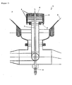
- FIG. 1 shows a filter 1 according to the invention for precoat filtration with a filter vessel 2 in a cutout in the region of the inlet manifold 4, which in the Unfiltratraum 3 protrudes.
- the inlet distributor 4 has in the example shown both at the top and at the side Area hole-shaped outlet openings 5.
- a regulating segment 6 is provided, which likewise has outlet openings 5.
- the regulating segment 6 is in this embodiment about the longitudinal axis L of the inlet manifold 4 rotatably formed, so that the hole-shaped outlet openings 5 of the main body G of the inlet manifold 4 with the outlet openings 5 of the Reguliersegments 6 can be brought at least partially overlapping.
- the outlet openings 5 are such arranged all positions between complete coverage the outlet openings 5 of the body G and more complete Overlap of these outlet openings 5 with the outlet openings 5 of the Reguliersegments 6 are einregelbar.
- the Rotation of the Reguliersegments 6 is in the embodiment by a linkage 7, preferably causes a threaded rod.
- the linkage 7 is preferably substantially in the interior of the inlet manifold 4 guided and in a lower portion of the filter 1 accessible from the outside. By rotation on the linkage. 7 is a change in the relative positioning of the regulation segment 6 achievable to the main body G of the inlet manifold 4, without requiring manual intervention in the interior of the filter bowl 2 would have to be made.
- rotations of the linkage 7 both purely manually and for example electrically or be effected pneumatically, in particular with servo motors.
- sealants in particular O-rings.
- outlet openings 5 arranged parallel to the longitudinal axis L of the filter 1.
- the outlet openings 5 and the longitudinal axis of the outlet openings 5 is arranged at an acute angle to the longitudinal axis L. are. At an acute angle are included Angle between 0 ° and 90 ° understood, in particular typically between 5 ° and 50 °.
- Angle between 0 ° and 90 ° understood, in particular typically between 5 ° and 50 °.
- the outlet openings are particularly preferred 5 of the main body G of the inlet manifold 4th aligned parallel to the longitudinal axis L, whereby the main body is particularly easy to produce. Only the outlet openings 5 of the Reguliersegments 6 then have the described acute angle, whereby a deflection and alignment of the to be entered medium in the region of the transition between the base body G and regulating segment 6 is effected. It has in particular shown that it is particularly advantageous if the Angle between different outlet openings 6 of the Reguliersegments and the longitudinal axis L are the sharper the closer the Outlet opening 5 of the longitudinal axis L is adjacent; hereby can be a particularly uniform flow behavior in the filter tank 2 be effected. In the embodiment shown is the upper end of the inlet manifold 4 through the Reguliersegment 6 formed in the shape of a truncated cone. hereby can be largely sediments by sedimenting particles be avoided during filtration and Trubaustrag.
- FIG. 2 shows a further embodiment of the invention in more detail Analogous to the embodiment shown in FIG. 1, however, here an intake manifold 4 is shown, which is constructed of annular disks.
- This embodiment clarifies that the invention in no way on with holes or Hole-shaped outlet openings 5 provided inlet manifold. 4 or Reguliersegmente is limited.
- FIG. 3 shows a filter 1 according to the invention for precoat filtration with a filter vessel 2 in a cutout in the region of the inlet manifold 4, which in the Unfiltratraum 3 protrudes.
- the inlet distributor 4 has in the example shown both at the top and at the side Area hole-shaped outlet openings 5.
- a hollow cylindrical Regulating segment 6 is provided, which also outlet openings 5 has.
- the regulating segment 6 is in this Embodiment around the longitudinal axis L of the inlet manifold 4th rotatably formed, so that the hole-shaped outlet openings 5 of the main body G of the inlet manifold 4 with the outlet openings 5 of the Reguliersegments 6 at least partially Overlapping can be brought.
- Particularly preferred are the Outlets 5derart arranged that all positions between complete coverage of the outlet openings 5 of the Body G and complete overlap of these outlet openings with the outlet openings 5 of the Reguliersegments 6 are einregelbar.
- the rotation of the regulating segment 6 is in the embodiment by a linkage 7, preferably a threaded rod causes.
- the linkage 7 is non-positive and / or in one piece by means of suspension T with the hollow cylindrical Regulating segment 6 connected.
- the linkage 7 is preferred guided essentially in the interior of the intake manifold 4 and accessible from the outside in a lower region of the filter 1.
- the adjustment and fixation of the linkage 7 can as already explained in the description of Figure 1. to Ensuring a permanent rotation in particular in the region of the linkage 7 and / or the contact area between Base G and regulating segment 6 bearing means provided be, if necessary in conjunction with sealants, in particular O-rings.
- the regulating segment is 6 rotatably formed about the longitudinal axis L.
- the Reguliersegment 6 could also and in particular additionally designed to be displaceable along the longitudinal axis be.
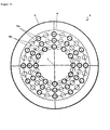
- Figure 4 is an inventive inlet manifold 4 with a Reguliersegment 6 in plan view along the longitudinal axis L. shown.
- the regulating segment 6 has outlet openings 5a
- the main body G of the inlet manifold 4 has outlet openings 5b, which are shown in phantom.
- By turning the regulating segment 6 about the longitudinal axis L of the inlet manifold 4 can the outlet openings 5a and 5b in at least partially overlapping to be brought. Particularly preferred are all positions between complete overlap of the outlet openings 5a and 5b and complete cover of the outlet openings 5b adjustable.
- outlet openings 5a and 5b in the form of circular bores or Restrict holes.
- the inlet manifold 4 arranged outlet openings 5 summarized and in particular in the form of circle segments be educated.
- the number of outlet openings 5a corresponds exactly to the number the outlet openings 5b.
- two sets of outlet openings 5a are usable, so for example special exit angles for special operating situations can be adjusted without changing the overall design or a manual intervention in the interior of the filter vessel would have to be made.
Landscapes
- Chemical & Material Sciences (AREA)
- Chemical Kinetics & Catalysis (AREA)
- Filtration Of Liquid (AREA)
- Filtering Of Dispersed Particles In Gases (AREA)
- Electrical Discharge Machining, Electrochemical Machining, And Combined Machining (AREA)
- Lubrication Details And Ventilation Of Internal Combustion Engines (AREA)
Abstract
Description
- Fig. 1:
- Filter mit Einlaufverteiler und Reguliersegment im Bereich des oberen Abschlusses des Einlaufverteilers; Einlaufverteiler mit lochförmigen Austrittsöffnungen.
- Fig. 2:
- Filter mit Einlaufverteiler und Reguliersegment im Bereich des oberen Abschlusses des Einlaufverteilers; Einlaufverteiler mit Austrittsspalten.
- Fig. 3:
- Einlaufverteiler mit hohlzylindrischem Reguliersegment in einem seitlichen Bereich.
- Fig. 4:
- Draufsicht auf einen Einlaufverteiler mit Reguliersegment.
Claims (10)
- Filter (1) für die Anschwemmfiltration, beinhaltend einen Filterkessel (2) mit einem Unfiltratraum (3), welcher in seinem unteren Bereich einen Einlaufverteiler (4) mit Austrittsöffnungen (5) aufweist,
dadurch gekennzeichnet, dass der Einlaufverteiler (4) derart konstruiert ist, dass die wirksame Anzahl und/oder der wirksame Querschnitt der Austrittsöffnungen (5) von ausserhalb des Filterkessels (2) variierbar sind. - Filter (1) nach Anspruch 1,
dadurch gekennzeichnet, dass die Variation der Anzahl und/oder des wirksamen Querschnitts der Austrittsöffnungen (5) durch zumindest teilweise Abdeckung von Austrittsöffnungen (5) bewirkbar ist. - Filter (1) nach einem der Ansprüche 1 bis 2,
dadurch gekennzeichnet, dass der Einlaufverteiler (4) zumindest ein von ausserhalb des Filterkessels (2) dreh- und/oder verschiebbares Reguliersegment (6) aufweist. - Filter (1) nach Anspruch 3,
dadurch gekennzeichnet, dass das Verdrehen und/oder Verschieben des Reguliersegments (6) mittels eines Gestänges (7) bewirkbar ist. - Filter (1) nach einem der Ansprüche 1 bis 4,
dadurch gekennzeichnet, dass mittels des Reguliersegments der Winkel zwischen Austrittsöffnungen (5) und der Längsachse (L) des Filters (1) von ausserhalb des Filterkessels variierbar ist. - Filter (1) nach einem der Ansprüche 3 bis 5,
dadurch gekennzeichnet, dass das Reguliersegment (6) drehund/oder verschiebbar im Bereich des oberen Abschlusses des Einlaufverteilers (4) angeordnet ist. - Filter (1) nach einem der Ansprüche 3 bis 5,
dadurch gekennzeichnet, dass das Reguliersegment (6) verdreh- und/oder verschiebbar in einem seitlichen Bereich des Einlaufverteilers (4) angeordnet ist. - Filter (1) nach Anspruch 7,
dadurch gekennzeichnet, dass das Reguliersegment (6) als mit Öffnungen versehener Hohlzylinder (6) ausgebildet ist. - Einlaufverteiler (4) für einen Filter (1) für die Anschwemmfiltration,
dadurch gekennzeichnet, dass der Einlaufverteiler (4) derart konstruiert ist, dass die wirksame Anzahl und/oder der wirksame Querschnitt der Austrittsöffnungen (5) von ausserhalb des Filterkessels (2) variierbar sind. - Verfahren zur Regulierung der Strömung innerhalb eines Filters (1) für die Anschwemmfiltration,
dadurch gekennzeichnet, dass die wirksame Anzahl und/oder der wirksame Querschnitt von Austrittsöffnungen (5) eines Einlaufverteilers (4) von ausserhalb des Filterkessels (2) variiert werden.
Priority Applications (3)
| Application Number | Priority Date | Filing Date | Title |
|---|---|---|---|
| EP03015075A EP1500420B1 (de) | 2003-07-03 | 2003-07-03 | Filter für Anschwemmfiltration, Einlaufverteiler für einen solchen Filter sowie Verfahren zur Regulierung der Strömung in einem solchen Filter |
| DE50306583T DE50306583D1 (de) | 2003-07-03 | 2003-07-03 | Filter für Anschwemmfiltration, Einlaufverteiler für einen solchen Filter sowie Verfahren zur Regulierung der Strömung in einem solchen Filter |
| AT03015075T ATE354415T1 (de) | 2003-07-03 | 2003-07-03 | Filter für anschwemmfiltration, einlaufverteiler für einen solchen filter sowie verfahren zur regulierung der strömung in einem solchen filter |
Applications Claiming Priority (1)
| Application Number | Priority Date | Filing Date | Title |
|---|---|---|---|
| EP03015075A EP1500420B1 (de) | 2003-07-03 | 2003-07-03 | Filter für Anschwemmfiltration, Einlaufverteiler für einen solchen Filter sowie Verfahren zur Regulierung der Strömung in einem solchen Filter |
Publications (2)
| Publication Number | Publication Date |
|---|---|
| EP1500420A1 true EP1500420A1 (de) | 2005-01-26 |
| EP1500420B1 EP1500420B1 (de) | 2007-02-21 |
Family
ID=33483907
Family Applications (1)
| Application Number | Title | Priority Date | Filing Date |
|---|---|---|---|
| EP03015075A Expired - Lifetime EP1500420B1 (de) | 2003-07-03 | 2003-07-03 | Filter für Anschwemmfiltration, Einlaufverteiler für einen solchen Filter sowie Verfahren zur Regulierung der Strömung in einem solchen Filter |
Country Status (3)
| Country | Link |
|---|---|
| EP (1) | EP1500420B1 (de) |
| AT (1) | ATE354415T1 (de) |
| DE (1) | DE50306583D1 (de) |
Citations (4)
| Publication number | Priority date | Publication date | Assignee | Title |
|---|---|---|---|---|
| WO1996014129A1 (de) * | 1994-11-03 | 1996-05-17 | Anton Steinecker Maschinenfabrik Gmbh | Kerzenfiltervorrichtung für die bierfiltration |
| US6076956A (en) * | 1996-06-26 | 2000-06-20 | Andritz-Patentverwaltungs-Gesselschaft M.B.H. | Device for distributing suspensions in a container |
| DE10005828A1 (de) * | 2000-02-10 | 2001-09-20 | Seitz Schenk Filtersystems Gmb | Verfahren und Vorrichtung zur Strömungsverteilung |
| WO2003024563A1 (de) * | 2001-09-17 | 2003-03-27 | Anton Steinecker Maschinenfabrik Gmbh | Einlaufverteiler für anschwemmfilter |
-
2003
- 2003-07-03 DE DE50306583T patent/DE50306583D1/de not_active Expired - Lifetime
- 2003-07-03 AT AT03015075T patent/ATE354415T1/de not_active IP Right Cessation
- 2003-07-03 EP EP03015075A patent/EP1500420B1/de not_active Expired - Lifetime
Patent Citations (4)
| Publication number | Priority date | Publication date | Assignee | Title |
|---|---|---|---|---|
| WO1996014129A1 (de) * | 1994-11-03 | 1996-05-17 | Anton Steinecker Maschinenfabrik Gmbh | Kerzenfiltervorrichtung für die bierfiltration |
| US6076956A (en) * | 1996-06-26 | 2000-06-20 | Andritz-Patentverwaltungs-Gesselschaft M.B.H. | Device for distributing suspensions in a container |
| DE10005828A1 (de) * | 2000-02-10 | 2001-09-20 | Seitz Schenk Filtersystems Gmb | Verfahren und Vorrichtung zur Strömungsverteilung |
| WO2003024563A1 (de) * | 2001-09-17 | 2003-03-27 | Anton Steinecker Maschinenfabrik Gmbh | Einlaufverteiler für anschwemmfilter |
Also Published As
| Publication number | Publication date |
|---|---|
| DE50306583D1 (de) | 2007-04-05 |
| EP1500420B1 (de) | 2007-02-21 |
| ATE354415T1 (de) | 2007-03-15 |
Similar Documents
| Publication | Publication Date | Title |
|---|---|---|
| DE3235552C2 (de) | Rückspülfilter | |
| EP3621717B1 (de) | Filtervorrichtung | |
| DE60005552T2 (de) | Schaltvorrichtung um einen fluidstrom nach wahl durch eine erste oder zweite behandlungsvorrichtung zu führen | |
| DE9212207U1 (de) | Druckminderer für eine Tiertränke | |
| DE19726187C1 (de) | Vorrichtung zum Injizieren von Fluiden in Lebensmittel | |
| DE2910053A1 (de) | Filtriervorrichtung | |
| EP0379054A2 (de) | Filtervorrichtung | |
| DE3505913A1 (de) | Fadenspannvorrichtung an einem spulengatter | |
| EP3896026A1 (de) | Füllorgan mit umstellung von freistrahl auf siebauslauf | |
| EP0810018B1 (de) | Rückspülbare Filteranordnung und Filterkerze | |
| DE2622094C3 (de) | Vorrichtung zur Sprühentgasung von Flüssigkeiten | |
| EP1500420B1 (de) | Filter für Anschwemmfiltration, Einlaufverteiler für einen solchen Filter sowie Verfahren zur Regulierung der Strömung in einem solchen Filter | |
| DE3886582T2 (de) | Filterapparat. | |
| DE4105867C2 (de) | Filtereinrichtung für flüssigen Kunststoff führende Druckleitungen | |
| EP1491247B1 (de) | Filter für die Anschwemmfiltration, Einlaufverteiler für einen solchen Filter sowie Verfahren zur Regulierung des Strömungsverhaltens in einem solchen Filter | |
| EP0789611B1 (de) | Kerzenfiltervorrichtung für die bierfiltration | |
| DE4237358A1 (de) | Stoffaustauschkolonne | |
| DE4210807A1 (de) | Luftdurchlaß | |
| EP0561857A1 (de) | Zentrifugalreinigungsfilter. | |
| EP1430940B1 (de) | Filter für die Anschwemmfiltration und Einlaufverteiler | |
| DE2757447B2 (de) | Rückspülbare Filtereinrichtung | |
| DE3215533A1 (de) | Rueckspuelbares filtergeraet | |
| WO2010075916A1 (de) | Verfahren und vorrichtung zur anschwemmfiltration von fluiden | |
| EP0655934B1 (de) | Druckfilter | |
| DE1291726B (de) | Rueckspuelbares Filter |
Legal Events
| Date | Code | Title | Description |
|---|---|---|---|
| PUAI | Public reference made under article 153(3) epc to a published international application that has entered the european phase |
Free format text: ORIGINAL CODE: 0009012 |
|
| AK | Designated contracting states |
Kind code of ref document: A1 Designated state(s): AT BE BG CH CY CZ DE DK EE ES FI FR GB GR HU IE IT LI LU MC NL PT RO SE SI SK TR |
|
| AX | Request for extension of the european patent |
Extension state: AL LT LV MK |
|
| 17P | Request for examination filed |
Effective date: 20050310 |
|
| AKX | Designation fees paid |
Designated state(s): AT BE BG CH CY CZ DE DK EE ES FI FR GB GR HU IE IT LI LU MC NL PT RO SE SI SK TR |
|
| GRAP | Despatch of communication of intention to grant a patent |
Free format text: ORIGINAL CODE: EPIDOSNIGR1 |
|
| GRAS | Grant fee paid |
Free format text: ORIGINAL CODE: EPIDOSNIGR3 |
|
| GRAA | (expected) grant |
Free format text: ORIGINAL CODE: 0009210 |
|
| AK | Designated contracting states |
Kind code of ref document: B1 Designated state(s): AT BE BG CH CY CZ DE DK EE ES FI FR GB GR HU IE IT LI LU MC NL PT RO SE SI SK TR |
|
| PG25 | Lapsed in a contracting state [announced via postgrant information from national office to epo] |
Ref country code: SI Free format text: LAPSE BECAUSE OF FAILURE TO SUBMIT A TRANSLATION OF THE DESCRIPTION OR TO PAY THE FEE WITHIN THE PRESCRIBED TIME-LIMIT Effective date: 20070221 Ref country code: FI Free format text: LAPSE BECAUSE OF FAILURE TO SUBMIT A TRANSLATION OF THE DESCRIPTION OR TO PAY THE FEE WITHIN THE PRESCRIBED TIME-LIMIT Effective date: 20070221 Ref country code: IE Free format text: LAPSE BECAUSE OF FAILURE TO SUBMIT A TRANSLATION OF THE DESCRIPTION OR TO PAY THE FEE WITHIN THE PRESCRIBED TIME-LIMIT Effective date: 20070221 Ref country code: DK Free format text: LAPSE BECAUSE OF FAILURE TO SUBMIT A TRANSLATION OF THE DESCRIPTION OR TO PAY THE FEE WITHIN THE PRESCRIBED TIME-LIMIT Effective date: 20070221 Ref country code: NL Free format text: LAPSE BECAUSE OF FAILURE TO SUBMIT A TRANSLATION OF THE DESCRIPTION OR TO PAY THE FEE WITHIN THE PRESCRIBED TIME-LIMIT Effective date: 20070221 |
|
| REG | Reference to a national code |
Ref country code: GB Ref legal event code: FG4D Free format text: NOT ENGLISH |
|
| REG | Reference to a national code |
Ref country code: CH Ref legal event code: EP |
|
| REG | Reference to a national code |
Ref country code: CH Ref legal event code: NV Representative=s name: HEPP, WENGER & RYFFEL AG |
|
| REF | Corresponds to: |
Ref document number: 50306583 Country of ref document: DE Date of ref document: 20070405 Kind code of ref document: P |
|
| REG | Reference to a national code |
Ref country code: IE Ref legal event code: FG4D Free format text: LANGUAGE OF EP DOCUMENT: GERMAN |
|
| PG25 | Lapsed in a contracting state [announced via postgrant information from national office to epo] |
Ref country code: SE Free format text: LAPSE BECAUSE OF FAILURE TO SUBMIT A TRANSLATION OF THE DESCRIPTION OR TO PAY THE FEE WITHIN THE PRESCRIBED TIME-LIMIT Effective date: 20070521 |
|
| PG25 | Lapsed in a contracting state [announced via postgrant information from national office to epo] |
Ref country code: BG Free format text: LAPSE BECAUSE OF EXPIRATION OF PROTECTION Effective date: 20070522 |
|
| PG25 | Lapsed in a contracting state [announced via postgrant information from national office to epo] |
Ref country code: ES Free format text: LAPSE BECAUSE OF FAILURE TO SUBMIT A TRANSLATION OF THE DESCRIPTION OR TO PAY THE FEE WITHIN THE PRESCRIBED TIME-LIMIT Effective date: 20070601 |
|
| PG25 | Lapsed in a contracting state [announced via postgrant information from national office to epo] |
Ref country code: PT Free format text: LAPSE BECAUSE OF FAILURE TO SUBMIT A TRANSLATION OF THE DESCRIPTION OR TO PAY THE FEE WITHIN THE PRESCRIBED TIME-LIMIT Effective date: 20070723 |
|
| NLV1 | Nl: lapsed or annulled due to failure to fulfill the requirements of art. 29p and 29m of the patents act | ||
| GBV | Gb: ep patent (uk) treated as always having been void in accordance with gb section 77(7)/1977 [no translation filed] |
Effective date: 20070221 |
|
| REG | Reference to a national code |
Ref country code: IE Ref legal event code: FD4D |
|
| EN | Fr: translation not filed | ||
| PG25 | Lapsed in a contracting state [announced via postgrant information from national office to epo] |
Ref country code: SK Free format text: LAPSE BECAUSE OF FAILURE TO SUBMIT A TRANSLATION OF THE DESCRIPTION OR TO PAY THE FEE WITHIN THE PRESCRIBED TIME-LIMIT Effective date: 20070221 Ref country code: GB Free format text: LAPSE BECAUSE OF FAILURE TO SUBMIT A TRANSLATION OF THE DESCRIPTION OR TO PAY THE FEE WITHIN THE PRESCRIBED TIME-LIMIT Effective date: 20070221 |
|
| PLBE | No opposition filed within time limit |
Free format text: ORIGINAL CODE: 0009261 |
|
| STAA | Information on the status of an ep patent application or granted ep patent |
Free format text: STATUS: NO OPPOSITION FILED WITHIN TIME LIMIT |
|
| PG25 | Lapsed in a contracting state [announced via postgrant information from national office to epo] |
Ref country code: CZ Free format text: LAPSE BECAUSE OF FAILURE TO SUBMIT A TRANSLATION OF THE DESCRIPTION OR TO PAY THE FEE WITHIN THE PRESCRIBED TIME-LIMIT Effective date: 20070221 Ref country code: RO Free format text: LAPSE BECAUSE OF FAILURE TO SUBMIT A TRANSLATION OF THE DESCRIPTION OR TO PAY THE FEE WITHIN THE PRESCRIBED TIME-LIMIT Effective date: 20070221 |
|
| 26N | No opposition filed |
Effective date: 20071122 |
|
| BERE | Be: lapsed |
Owner name: FILTROX A.G. Effective date: 20070731 |
|
| PG25 | Lapsed in a contracting state [announced via postgrant information from national office to epo] |
Ref country code: FR Free format text: LAPSE BECAUSE OF FAILURE TO SUBMIT A TRANSLATION OF THE DESCRIPTION OR TO PAY THE FEE WITHIN THE PRESCRIBED TIME-LIMIT Effective date: 20071012 Ref country code: GR Free format text: LAPSE BECAUSE OF FAILURE TO SUBMIT A TRANSLATION OF THE DESCRIPTION OR TO PAY THE FEE WITHIN THE PRESCRIBED TIME-LIMIT Effective date: 20070522 Ref country code: IT Free format text: LAPSE BECAUSE OF FAILURE TO SUBMIT A TRANSLATION OF THE DESCRIPTION OR TO PAY THE FEE WITHIN THE PRESCRIBED TIME-LIMIT Effective date: 20070221 Ref country code: MC Free format text: LAPSE BECAUSE OF NON-PAYMENT OF DUE FEES Effective date: 20070731 |
|
| PG25 | Lapsed in a contracting state [announced via postgrant information from national office to epo] |
Ref country code: BE Free format text: LAPSE BECAUSE OF NON-PAYMENT OF DUE FEES Effective date: 20070731 |
|
| PG25 | Lapsed in a contracting state [announced via postgrant information from national office to epo] |
Ref country code: AT Free format text: LAPSE BECAUSE OF NON-PAYMENT OF DUE FEES Effective date: 20070703 Ref country code: FR Free format text: LAPSE BECAUSE OF FAILURE TO SUBMIT A TRANSLATION OF THE DESCRIPTION OR TO PAY THE FEE WITHIN THE PRESCRIBED TIME-LIMIT Effective date: 20070221 |
|
| PG25 | Lapsed in a contracting state [announced via postgrant information from national office to epo] |
Ref country code: EE Free format text: LAPSE BECAUSE OF FAILURE TO SUBMIT A TRANSLATION OF THE DESCRIPTION OR TO PAY THE FEE WITHIN THE PRESCRIBED TIME-LIMIT Effective date: 20070221 |
|
| PG25 | Lapsed in a contracting state [announced via postgrant information from national office to epo] |
Ref country code: CY Free format text: LAPSE BECAUSE OF FAILURE TO SUBMIT A TRANSLATION OF THE DESCRIPTION OR TO PAY THE FEE WITHIN THE PRESCRIBED TIME-LIMIT Effective date: 20070221 |
|
| PG25 | Lapsed in a contracting state [announced via postgrant information from national office to epo] |
Ref country code: LU Free format text: LAPSE BECAUSE OF NON-PAYMENT OF DUE FEES Effective date: 20070703 |
|
| PG25 | Lapsed in a contracting state [announced via postgrant information from national office to epo] |
Ref country code: HU Free format text: LAPSE BECAUSE OF FAILURE TO SUBMIT A TRANSLATION OF THE DESCRIPTION OR TO PAY THE FEE WITHIN THE PRESCRIBED TIME-LIMIT Effective date: 20070822 Ref country code: TR Free format text: LAPSE BECAUSE OF FAILURE TO SUBMIT A TRANSLATION OF THE DESCRIPTION OR TO PAY THE FEE WITHIN THE PRESCRIBED TIME-LIMIT Effective date: 20070221 |
|
| REG | Reference to a national code |
Ref country code: CH Ref legal event code: PUE Owner name: FILTROX ENGINEERING AG, CH Free format text: FORMER OWNER: FILTROX AG, CH |
|
| REG | Reference to a national code |
Ref country code: DE Ref legal event code: R082 Ref document number: 50306583 Country of ref document: DE Representative=s name: ISARPATENT GBR PATENT- UND RECHTSANWAELTE, DE Effective date: 20121122 Ref country code: DE Ref legal event code: R081 Ref document number: 50306583 Country of ref document: DE Owner name: FILTROX ENGINEERING AG, CH Free format text: FORMER OWNER: FILTROX AG, 9001 ST. GALLEN, CH Effective date: 20121122 Ref country code: DE Ref legal event code: R082 Ref document number: 50306583 Country of ref document: DE Representative=s name: ISARPATENT PATENTANWAELTE BEHNISCH, BARTH, CHA, DE Effective date: 20121122 |
|
| PGFP | Annual fee paid to national office [announced via postgrant information from national office to epo] |
Ref country code: CH Payment date: 20140930 Year of fee payment: 12 Ref country code: DE Payment date: 20140625 Year of fee payment: 12 |
|
| REG | Reference to a national code |
Ref country code: DE Ref legal event code: R119 Ref document number: 50306583 Country of ref document: DE |
|
| REG | Reference to a national code |
Ref country code: CH Ref legal event code: PL |
|
| PG25 | Lapsed in a contracting state [announced via postgrant information from national office to epo] |
Ref country code: CH Free format text: LAPSE BECAUSE OF NON-PAYMENT OF DUE FEES Effective date: 20150731 Ref country code: LI Free format text: LAPSE BECAUSE OF NON-PAYMENT OF DUE FEES Effective date: 20150731 Ref country code: DE Free format text: LAPSE BECAUSE OF NON-PAYMENT OF DUE FEES Effective date: 20160202 |