EP1500472A1 - Appareil d'entraínement d'éléments de fixation à sabot de sécurité - Google Patents
Appareil d'entraínement d'éléments de fixation à sabot de sécurité Download PDFInfo
- Publication number
- EP1500472A1 EP1500472A1 EP04291786A EP04291786A EP1500472A1 EP 1500472 A1 EP1500472 A1 EP 1500472A1 EP 04291786 A EP04291786 A EP 04291786A EP 04291786 A EP04291786 A EP 04291786A EP 1500472 A1 EP1500472 A1 EP 1500472A1
- Authority
- EP
- European Patent Office
- Prior art keywords
- barrel
- shoe
- safety
- guide
- tip
- Prior art date
- Legal status (The legal status is an assumption and is not a legal conclusion. Google has not performed a legal analysis and makes no representation as to the accuracy of the status listed.)
- Granted
Links
- 230000000007 visual effect Effects 0.000 abstract 1
- 238000010304 firing Methods 0.000 description 3
- 239000000463 material Substances 0.000 description 3
- 238000007789 sealing Methods 0.000 description 2
- 230000003466 anti-cipated effect Effects 0.000 description 1
- 238000002485 combustion reaction Methods 0.000 description 1
- 230000002950 deficient Effects 0.000 description 1
- 238000004880 explosion Methods 0.000 description 1
- 230000007257 malfunction Effects 0.000 description 1
- 239000000203 mixture Substances 0.000 description 1
- 239000000843 powder Substances 0.000 description 1
- 230000033764 rhythmic process Effects 0.000 description 1
Images

Classifications
-
- B—PERFORMING OPERATIONS; TRANSPORTING
- B25—HAND TOOLS; PORTABLE POWER-DRIVEN TOOLS; MANIPULATORS
- B25C—HAND-HELD NAILING OR STAPLING TOOLS; MANUALLY OPERATED PORTABLE STAPLING TOOLS
- B25C1/00—Hand-held nailing tools; Nail feeding devices
- B25C1/008—Safety devices
-
- B—PERFORMING OPERATIONS; TRANSPORTING
- B25—HAND TOOLS; PORTABLE POWER-DRIVEN TOOLS; MANIPULATORS
- B25C—HAND-HELD NAILING OR STAPLING TOOLS; MANUALLY OPERATED PORTABLE STAPLING TOOLS
- B25C1/00—Hand-held nailing tools; Nail feeding devices
- B25C1/08—Hand-held nailing tools; Nail feeding devices operated by combustion pressure
- B25C1/10—Hand-held nailing tools; Nail feeding devices operated by combustion pressure generated by detonation of a cartridge
- B25C1/18—Details and accessories, e.g. splinter guards, spall minimisers
- B25C1/182—Feeding devices
- B25C1/184—Feeding devices for nails
Definitions
- the present application relates to a device for training elements of fixation of the nail or staple type - this is a nailer or stapler - comprising a barrel with, at the front, an arranged guide-element to go back when putting the device in support, a shop supply unit for receiving a loader of fasteners and for introduce an element into the barrel, and support safety means, arranged to authorize the driving of a fastener only after recess of the element-guide and comprising a safety shoe arranged for, in the absence of any element in the barrel, be moved to a safe position and prevent the retreat of the element guide.
- the device concerned here is a priori so-called gun of indirect fire sealing, in which a counterweight, intended for the training of a point, a buffer or any other element analogous, is propelled forward under the action of the combustion of a powder charge or explosion of a flammable gas mixture.
- the element guide is more commonly called a tip guide.
- This guide is often distinct from the barrel and mounted at the front of the barrel. Sometimes the part before the cannon acts as a guide-tip and, in this case, it's all the barrel which is arranged to be moved backwards when support of the device, as part of the support security.
- the loader includes an introductory pusher one by one fasteners in the barrel of the device, with a warning light pusher.
- the pusher advance indicator does not tell if there is still a element in the barrel or not, ie if this element has already been used or not.
- the invention of the present application aims to overcome this drawback and to to offer the user of the device the comfort of a good information, him avoiding the question of whether the barrel of his device is empty or if the device has a malfunction.
- the present application relates to an apparatus of the type specified above, characterized by the fact that it includes a witness of the safety position of the safety shoe.
- control comprises a pawn secured to the shoe and slidably mounted, from a position of operating at a safety position, in a well opening into an opening of the surface of the housing of the device.
- the pin has a length such that, in the position of functioning, its free end is visible in the opening of the well and hidden in safety position.
- the shoe and the witness are formed in one piece.
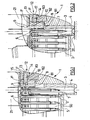
- the apparatus 1 for training elements of fixing here a sealing pistol, comprises a guide element 4, formed by the front portion of the barrel 3 of the pistol 1, and a feed magazine 5 in which is received a charger 50 of fasteners, here spikes 2, 7, joined in a string by guide pins 6.
- the tips 2, 7 are kept aligned and, thanks to a push 11, pushed one by one into the barrel, to the rhythm of the shots.
- the tip guide 4 can slide rearward 21 of the gun when it is in support on a support material 20 in which one wants to drive a tip.
- a safety shoe 8 arranged to prevent the guide-tip 4 backward if the barrel 3 is empty, as shown in FIG.
- the shoe 8 essentially consists of a shoe substantially parallelepiped 81 having a finger 82, also parallelepiped, arranged to fit into a groove 9 of the guide-tip when the shoe 81 is in the barrel, and to disengage when said pad is pushed out of the barrel, and having a cylindrical piston 83 arranged to slide in a well 14 formed in the housing of the gun.
- the shoe 8 is pushed transversely to the axis of the barrel by a helical spring 10 surrounding the piston 83, and is guided in this direction by said piston.
- the action of the spring 10 on the shoe 81 of the shoe 8 is not compensated by the pusher 11 of the charger 50, a tip 7 not being not present in the barrel, the finger 82 enters the groove 9 of the tip guide 4, thus preventing its setting support position and any subsequent shot. If a tip 7 is present, the finger 82 is released from the groove 9, the guide-tip is unlocked and a shot can be made.
- a progress indicator of the pusher 11 (not shown) which indicates its position in the magazine 50, and in particular if it is in stop at the top of the loader, as in Figure 3, but this indicator is deficient to indicate if the firing of the last tip of the magazine was carried out or not, since it does not change position as a result of this shot. The user can then remain in uncertainty as to whether there is still a spike in the barrel or not.
- the pistol will also include a position of the safety shoe 8.
- the shoe 8 comprises a pin 13 which it is integral (or monobloc with it) sliding, with the piston 83, in the well 14 which opens into an opening 15 of the surface 16 of the housing of the gun.
- the pin 13 is simply an extension of the piston 83.
Landscapes
- Engineering & Computer Science (AREA)
- Mechanical Engineering (AREA)
- Chemical & Material Sciences (AREA)
- Combustion & Propulsion (AREA)
- Portable Nailing Machines And Staplers (AREA)
- Telephone Function (AREA)
- Toys (AREA)
- Helmets And Other Head Coverings (AREA)
Abstract
Description
- la figure 1 représente une vue en coupe, selon l'axe du canon, de l'appareil de l'invention quand il est chargé et en position de repos ;
- la figure 2 représente une vue, selon la même coupe, de l'appareil de l'invention quand il est chargé et en position de tir ;
- la figure 3 représente une vue, selon la même coupe, de l'appareil de l'invention, en position de repos, quand le chargeur est vide , et
- la figure 4 représente une vue en coupe, selon un plan orthogonal à l'axe du canon et passant par le témoin, de l'appareil de l'invention quand le chargeur est vide.
Claims (4)
- Appareil (1) d'entraínement d'éléments de fixation (2) comprenant un canon (3) avec, à l'avant, un guide-élément (4) agencé pour reculer lors d'une mise en appui de l'appareil, un magasin (5) d'alimentation, destiné à recevoir un chargeur (50) d'éléments de fixation et à introduire un élément (7) dans le canon, et des moyens de sécurité d'appui, agencés pour n'autoriser l'entraínement d'un élément de fixation qu'après recul du guide-élément et comprenant un sabot de sécurité (8) agencé pour, en l'absence d'élément (7) dans le canon, être déplacé en position de sécurité et empêcher le recul du guide-élément, caractérisé par le fait qu'il comporte un témoin (12) de la position de sécurité du sabot de sécurité (8).
- Appareil selon la revendication 1, dans lequel le témoin (12) comporte un pion (13) solidaire du sabot (8) et monté coulissant, d'une position (F) de fonctionnement à une position (S) de sécurité, dans un puits (14) débouchant dans une ouverture (15) de la surface (16) du boítier de l'appareil.
- Appareil selon la revendication 2, dans lequel le pion (13) a une longueur telle que, en position de fonctionnement (F), son extrémité libre (17) est visible dans l'ouverture (15) du puits (14) et cachée en position de sécurité (S).
- Appareil selon l'une des revendications 1 à 3, dans lequel le sabot (8) et le témoin (12) sont formés d'une seule pièce.
Applications Claiming Priority (2)
| Application Number | Priority Date | Filing Date | Title |
|---|---|---|---|
| FR0308999A FR2857896B1 (fr) | 2003-07-23 | 2003-07-23 | Appareil d'entrainement d'elements de fixation a sabot de securite |
| FR0308999 | 2003-07-23 |
Publications (2)
| Publication Number | Publication Date |
|---|---|
| EP1500472A1 true EP1500472A1 (fr) | 2005-01-26 |
| EP1500472B1 EP1500472B1 (fr) | 2007-03-21 |
Family
ID=33484692
Family Applications (1)
| Application Number | Title | Priority Date | Filing Date |
|---|---|---|---|
| EP04291786A Expired - Lifetime EP1500472B1 (fr) | 2003-07-23 | 2004-07-13 | Appareil d'entraînement d'éléments de fixation à sabot de sécurité |
Country Status (9)
| Country | Link |
|---|---|
| US (1) | US7059507B2 (fr) |
| EP (1) | EP1500472B1 (fr) |
| AT (1) | ATE357314T1 (fr) |
| AU (1) | AU2004203174B2 (fr) |
| CA (1) | CA2473632C (fr) |
| DE (1) | DE602004005381T2 (fr) |
| ES (1) | ES2283958T3 (fr) |
| FR (1) | FR2857896B1 (fr) |
| NZ (1) | NZ534131A (fr) |
Families Citing this family (25)
| Publication number | Priority date | Publication date | Assignee | Title |
|---|---|---|---|---|
| US7971768B2 (en) * | 2004-05-04 | 2011-07-05 | Illinois Tool Works Inc. | Guidance system for fasteners |
| KR200389873Y1 (ko) * | 2005-04-20 | 2005-07-18 | 제일타카 주식회사 | 타카장치의 네일 낙하방지부재 |
| US7182236B1 (en) * | 2005-11-23 | 2007-02-27 | De Poan Pneumatic Corp. | Braking mechanism for nail driver |
| US7344057B2 (en) * | 2006-05-02 | 2008-03-18 | Laboratoire Primatech Inc. | Nailer with adjustable guide member |
| DE102006000254A1 (de) * | 2006-05-30 | 2007-12-06 | Hilti Ag | Handgeführtes Setzgerät |
| DE102006035459A1 (de) * | 2006-11-27 | 2008-05-29 | Hilti Ag | Handgeführtes Eintreibgerät |
| US8711833B2 (en) * | 2007-04-18 | 2014-04-29 | Wi-Lan, Inc. | Base station synchronization for a single frequency network |
| JP5395333B2 (ja) * | 2007-05-11 | 2014-01-22 | 日立工機株式会社 | 打込機 |
| US8276798B2 (en) | 2007-06-21 | 2012-10-02 | Illinois Tool Works Inc. | Feeder mechanism retention device for fastener driving tool |
| US8104658B2 (en) * | 2007-11-20 | 2012-01-31 | De Poan Pneumatic Corp. | Block device for nail gun |
| DE102008001969A1 (de) * | 2008-05-26 | 2009-12-03 | Hilti Aktiengesellschaft | Handgeführtes elektrisch betriebenes Eintreibgerät |
| DE102008054483A1 (de) | 2008-12-10 | 2010-06-17 | Hilti Aktiengesellschaft | Freischaltadapter für Einzelsetzungen mit handgeführten Setzgeräten |
| US8746526B2 (en) * | 2009-09-15 | 2014-06-10 | Robert Bosch Gmbh | Fastener driver with blank fire lockout |
| US8336748B2 (en) * | 2009-09-15 | 2012-12-25 | Robert Bosch Gmbh | Fastener driver with driver assembly blocking member |
| TWI383867B (zh) * | 2010-08-20 | 2013-02-01 | Apex Mfg Co Ltd | 導釘結構及具有該導釘結構之釘槍 |
| US9221163B2 (en) | 2010-08-20 | 2015-12-29 | Apex Mfg. Co., Ltd. | Nail guider and nailing device having the same |
| US8292143B2 (en) | 2010-10-12 | 2012-10-23 | Stanley Fastening Systems, L.P. | Dry fire lockout with bypass for fastener driving device |
| US20130193182A1 (en) * | 2012-02-01 | 2013-08-01 | Samson Power Tool Co., Ltd. | Nail guiding device for coil nailer |
| FR2993810B1 (fr) * | 2012-07-25 | 2014-07-11 | Illinois Tool Works | Outil de fixation par tir indirect, a support de detente anti-tir |
| CN104354142B (zh) * | 2014-10-22 | 2017-01-11 | 四川南山射钉紧固器材有限公司 | 一种排钉枪的钉管保险装置 |
| WO2016127101A1 (fr) | 2015-02-06 | 2016-08-11 | Milwaukee Electric Tool Corporation | Dispositif d'entraînement de fixation alimenté par ressort à gaz |
| TWI558517B (zh) * | 2016-02-03 | 2016-11-21 | 堡勝企業股份有限公司 | 打釘機之導釘結構 |
| WO2021236940A1 (fr) | 2020-05-22 | 2021-11-25 | Milwaukee Electric Tool Corporation | Mécanisme de verrouillage de tir à vide et de retenue de dernière agrafe pour pistolet à agrafes électrique |
| US12202112B2 (en) | 2021-01-20 | 2025-01-21 | Milwaukee Electric Tool Corporation | Powered fastener driver |
| WO2022159538A1 (fr) | 2021-01-20 | 2022-07-28 | Milwaukee Electric Tool Corporation | Dispositif d'entraînement d'élément de fixation électrique |
Citations (2)
| Publication number | Priority date | Publication date | Assignee | Title |
|---|---|---|---|---|
| US5167359A (en) * | 1990-10-11 | 1992-12-01 | Hilti Aktiengesellschaft | Setting device for fastening elements |
| EP0987086A2 (fr) * | 1998-09-18 | 2000-03-22 | Ramset Fasteners (Aust.) Pty. Ltd. | Outils motorisés comportant un mécanisme d'alimentation du type à chargeur |
Family Cites Families (7)
| Publication number | Priority date | Publication date | Assignee | Title |
|---|---|---|---|---|
| US3893610A (en) * | 1974-03-13 | 1975-07-08 | Arthur J Smith | Pneumatic device for driving headed objects |
| ATE162449T1 (de) * | 1988-04-07 | 1998-02-15 | Pittini Alessandra | Pneumatisches befestigungsmitteleintreibgerät |
| US5441191A (en) * | 1993-12-30 | 1995-08-15 | Linden; Gerald E. | Indicating "staples low" in a paper stapler |
| DE19517230A1 (de) * | 1995-05-15 | 1996-11-21 | Hilti Ag | Pulverkraftbetriebenes Setzgerät mit Magazin für Befestigungselemente |
| US6056181A (en) * | 1999-08-24 | 2000-05-02 | Besco Pneumatic Corp. | Fastening machine |
| DE19950349B4 (de) * | 1999-10-19 | 2006-07-27 | Hilti Ag | Setzgerät für Befestigungselemente |
| DE20119463U1 (de) * | 2001-11-29 | 2002-01-24 | Hilti Ag, Schaan | Tragbares, brennkraftbetriebenes Setzgerät für Befestigungselemente |
-
2003
- 2003-07-23 FR FR0308999A patent/FR2857896B1/fr not_active Expired - Fee Related
-
2004
- 2004-07-08 US US10/885,780 patent/US7059507B2/en not_active Expired - Lifetime
- 2004-07-13 ES ES04291786T patent/ES2283958T3/es not_active Expired - Lifetime
- 2004-07-13 EP EP04291786A patent/EP1500472B1/fr not_active Expired - Lifetime
- 2004-07-13 DE DE602004005381T patent/DE602004005381T2/de not_active Expired - Lifetime
- 2004-07-13 CA CA002473632A patent/CA2473632C/fr not_active Expired - Fee Related
- 2004-07-13 AT AT04291786T patent/ATE357314T1/de not_active IP Right Cessation
- 2004-07-14 AU AU2004203174A patent/AU2004203174B2/en not_active Ceased
- 2004-07-15 NZ NZ534131A patent/NZ534131A/xx not_active IP Right Cessation
Patent Citations (2)
| Publication number | Priority date | Publication date | Assignee | Title |
|---|---|---|---|---|
| US5167359A (en) * | 1990-10-11 | 1992-12-01 | Hilti Aktiengesellschaft | Setting device for fastening elements |
| EP0987086A2 (fr) * | 1998-09-18 | 2000-03-22 | Ramset Fasteners (Aust.) Pty. Ltd. | Outils motorisés comportant un mécanisme d'alimentation du type à chargeur |
Also Published As
| Publication number | Publication date |
|---|---|
| CA2473632C (fr) | 2008-03-18 |
| FR2857896A1 (fr) | 2005-01-28 |
| DE602004005381T2 (de) | 2007-11-29 |
| US20050017046A1 (en) | 2005-01-27 |
| US7059507B2 (en) | 2006-06-13 |
| NZ534131A (en) | 2004-12-24 |
| DE602004005381D1 (de) | 2007-05-03 |
| AU2004203174A1 (en) | 2005-02-10 |
| FR2857896B1 (fr) | 2007-04-27 |
| CA2473632A1 (fr) | 2005-01-23 |
| ES2283958T3 (es) | 2007-11-01 |
| ATE357314T1 (de) | 2007-04-15 |
| AU2004203174B2 (en) | 2007-01-25 |
| EP1500472B1 (fr) | 2007-03-21 |
Similar Documents
| Publication | Publication Date | Title |
|---|---|---|
| EP1500472B1 (fr) | Appareil d'entraînement d'éléments de fixation à sabot de sécurité | |
| EP0128069B1 (fr) | Dispositif d'alimentation pour appareil à gaz comprimé de tir semi-automatique de projectiles | |
| US4858811A (en) | Power actuated tool with magazine feed | |
| EP1486294B1 (fr) | Perche de télé actionnement d'un outil à main | |
| US5402594A (en) | Magazine cartridge loader | |
| US5273198A (en) | Powder-actuated, fastener-driving tool | |
| JPH02502360A (ja) | 火薬‐作動留め具打込み工具 | |
| US4687126A (en) | Power actuated tool for driving fastener | |
| CA1126070A (fr) | Pistolet perfectionne | |
| EP0573093A1 (fr) | Dispositif pour le freinage de la glissière d'une arme à feu | |
| US4074843A (en) | Fastening element feeding device for an explosive powder driven setting gun | |
| FR2832663A1 (fr) | Outil de scellement portatif actionne par combustion interne pour elements de fixation | |
| US7059074B1 (en) | Muzzle-loading firearm | |
| WO1983002998A1 (fr) | Arme a feu automatique de poing | |
| FR2545402A1 (fr) | ||
| EP0314549B1 (fr) | Appareil de scellement à extracteur perfectionné | |
| FR2952567A1 (fr) | Appareil de scellement a tir indirect a securite de positionnement spatial et perche, de teleactionnement d'un appareil de scellement a tir indirect, a securite de positionnement spatial | |
| FR2536526A1 (fr) | Dispositif de securite pour appareil actionne a poudre | |
| FR2766403A1 (fr) | Bande de bagues de reception de tampon de scellement pour appareil de scellement de tampon | |
| CA1037652A (fr) | Outil de pose d'elements de fixation par detonation engendree par un coup de marteau | |
| FR2887483A1 (fr) | Appareil de fixation a levier d'ouverture | |
| FR2765317A1 (fr) | Mecanisme d'armement desarmable pour fusil | |
| KR950005547Y1 (ko) | 공기총의 공기저장통 착탈장치 | |
| CH580268A5 (en) | Cartridge ejector for firearm - makes cartridge tilt in slot in breech when pulled backwards by hooked ejector finger | |
| FR2993810A1 (fr) | Outil de fixation par tir indirect, a support de detente anti-tir |
Legal Events
| Date | Code | Title | Description |
|---|---|---|---|
| PUAI | Public reference made under article 153(3) epc to a published international application that has entered the european phase |
Free format text: ORIGINAL CODE: 0009012 |
|
| AK | Designated contracting states |
Kind code of ref document: A1 Designated state(s): AT BE BG CH CY CZ DE DK EE ES FI FR GB GR HU IE IT LI LU MC NL PL PT RO SE SI SK TR |
|
| AX | Request for extension of the european patent |
Extension state: AL HR LT LV MK |
|
| AKX | Designation fees paid |
Designated state(s): AT BE BG CH CY CZ DE DK EE ES FI FR GB GR HU IE IT LI LU MC NL PL PT RO SE SI SK TR |
|
| 17P | Request for examination filed |
Effective date: 20050716 |
|
| GRAP | Despatch of communication of intention to grant a patent |
Free format text: ORIGINAL CODE: EPIDOSNIGR1 |
|
| GRAS | Grant fee paid |
Free format text: ORIGINAL CODE: EPIDOSNIGR3 |
|
| GRAA | (expected) grant |
Free format text: ORIGINAL CODE: 0009210 |
|
| AK | Designated contracting states |
Kind code of ref document: B1 Designated state(s): AT BE BG CH CY CZ DE DK EE ES FI FR GB GR HU IE IT LI LU MC NL PL PT RO SE SI SK TR |
|
| PG25 | Lapsed in a contracting state [announced via postgrant information from national office to epo] |
Ref country code: SI Free format text: LAPSE BECAUSE OF FAILURE TO SUBMIT A TRANSLATION OF THE DESCRIPTION OR TO PAY THE FEE WITHIN THE PRESCRIBED TIME-LIMIT Effective date: 20070321 Ref country code: AT Free format text: LAPSE BECAUSE OF FAILURE TO SUBMIT A TRANSLATION OF THE DESCRIPTION OR TO PAY THE FEE WITHIN THE PRESCRIBED TIME-LIMIT Effective date: 20070321 Ref country code: FI Free format text: LAPSE BECAUSE OF FAILURE TO SUBMIT A TRANSLATION OF THE DESCRIPTION OR TO PAY THE FEE WITHIN THE PRESCRIBED TIME-LIMIT Effective date: 20070321 Ref country code: PL Free format text: LAPSE BECAUSE OF FAILURE TO SUBMIT A TRANSLATION OF THE DESCRIPTION OR TO PAY THE FEE WITHIN THE PRESCRIBED TIME-LIMIT Effective date: 20070321 |
|
| REG | Reference to a national code |
Ref country code: GB Ref legal event code: FG4D Free format text: NOT ENGLISH |
|
| REG | Reference to a national code |
Ref country code: CH Ref legal event code: EP |
|
| REF | Corresponds to: |
Ref document number: 602004005381 Country of ref document: DE Date of ref document: 20070503 Kind code of ref document: P |
|
| REG | Reference to a national code |
Ref country code: IE Ref legal event code: FG4D Free format text: LANGUAGE OF EP DOCUMENT: FRENCH |
|
| REG | Reference to a national code |
Ref country code: SE Ref legal event code: TRGR |
|
| GBT | Gb: translation of ep patent filed (gb section 77(6)(a)/1977) |
Effective date: 20070522 |
|
| PG25 | Lapsed in a contracting state [announced via postgrant information from national office to epo] |
Ref country code: PT Free format text: LAPSE BECAUSE OF FAILURE TO SUBMIT A TRANSLATION OF THE DESCRIPTION OR TO PAY THE FEE WITHIN THE PRESCRIBED TIME-LIMIT Effective date: 20070821 |
|
| REG | Reference to a national code |
Ref country code: ES Ref legal event code: FG2A Ref document number: 2283958 Country of ref document: ES Kind code of ref document: T3 |
|
| PG25 | Lapsed in a contracting state [announced via postgrant information from national office to epo] |
Ref country code: SK Free format text: LAPSE BECAUSE OF FAILURE TO SUBMIT A TRANSLATION OF THE DESCRIPTION OR TO PAY THE FEE WITHIN THE PRESCRIBED TIME-LIMIT Effective date: 20070321 |
|
| PG25 | Lapsed in a contracting state [announced via postgrant information from national office to epo] |
Ref country code: RO Free format text: LAPSE BECAUSE OF FAILURE TO SUBMIT A TRANSLATION OF THE DESCRIPTION OR TO PAY THE FEE WITHIN THE PRESCRIBED TIME-LIMIT Effective date: 20070321 Ref country code: CZ Free format text: LAPSE BECAUSE OF FAILURE TO SUBMIT A TRANSLATION OF THE DESCRIPTION OR TO PAY THE FEE WITHIN THE PRESCRIBED TIME-LIMIT Effective date: 20070321 |
|
| PLBE | No opposition filed within time limit |
Free format text: ORIGINAL CODE: 0009261 |
|
| STAA | Information on the status of an ep patent application or granted ep patent |
Free format text: STATUS: NO OPPOSITION FILED WITHIN TIME LIMIT |
|
| PG25 | Lapsed in a contracting state [announced via postgrant information from national office to epo] |
Ref country code: DK Free format text: LAPSE BECAUSE OF FAILURE TO SUBMIT A TRANSLATION OF THE DESCRIPTION OR TO PAY THE FEE WITHIN THE PRESCRIBED TIME-LIMIT Effective date: 20070321 |
|
| 26N | No opposition filed |
Effective date: 20071227 |
|
| PG25 | Lapsed in a contracting state [announced via postgrant information from national office to epo] |
Ref country code: GR Free format text: LAPSE BECAUSE OF FAILURE TO SUBMIT A TRANSLATION OF THE DESCRIPTION OR TO PAY THE FEE WITHIN THE PRESCRIBED TIME-LIMIT Effective date: 20070622 Ref country code: MC Free format text: LAPSE BECAUSE OF NON-PAYMENT OF DUE FEES Effective date: 20070731 |
|
| PG25 | Lapsed in a contracting state [announced via postgrant information from national office to epo] |
Ref country code: EE Free format text: LAPSE BECAUSE OF FAILURE TO SUBMIT A TRANSLATION OF THE DESCRIPTION OR TO PAY THE FEE WITHIN THE PRESCRIBED TIME-LIMIT Effective date: 20070321 |
|
| REG | Reference to a national code |
Ref country code: CH Ref legal event code: PL |
|
| PG25 | Lapsed in a contracting state [announced via postgrant information from national office to epo] |
Ref country code: LI Free format text: LAPSE BECAUSE OF NON-PAYMENT OF DUE FEES Effective date: 20080731 Ref country code: CH Free format text: LAPSE BECAUSE OF NON-PAYMENT OF DUE FEES Effective date: 20080731 |
|
| PG25 | Lapsed in a contracting state [announced via postgrant information from national office to epo] |
Ref country code: CY Free format text: LAPSE BECAUSE OF FAILURE TO SUBMIT A TRANSLATION OF THE DESCRIPTION OR TO PAY THE FEE WITHIN THE PRESCRIBED TIME-LIMIT Effective date: 20070321 |
|
| PG25 | Lapsed in a contracting state [announced via postgrant information from national office to epo] |
Ref country code: LU Free format text: LAPSE BECAUSE OF NON-PAYMENT OF DUE FEES Effective date: 20070713 Ref country code: BG Free format text: LAPSE BECAUSE OF FAILURE TO SUBMIT A TRANSLATION OF THE DESCRIPTION OR TO PAY THE FEE WITHIN THE PRESCRIBED TIME-LIMIT Effective date: 20070621 |
|
| PG25 | Lapsed in a contracting state [announced via postgrant information from national office to epo] |
Ref country code: TR Free format text: LAPSE BECAUSE OF FAILURE TO SUBMIT A TRANSLATION OF THE DESCRIPTION OR TO PAY THE FEE WITHIN THE PRESCRIBED TIME-LIMIT Effective date: 20070321 Ref country code: HU Free format text: LAPSE BECAUSE OF FAILURE TO SUBMIT A TRANSLATION OF THE DESCRIPTION OR TO PAY THE FEE WITHIN THE PRESCRIBED TIME-LIMIT Effective date: 20070922 |
|
| PGFP | Annual fee paid to national office [announced via postgrant information from national office to epo] |
Ref country code: IE Payment date: 20110725 Year of fee payment: 8 |
|
| PGFP | Annual fee paid to national office [announced via postgrant information from national office to epo] |
Ref country code: GB Payment date: 20120725 Year of fee payment: 9 Ref country code: SE Payment date: 20120727 Year of fee payment: 9 |
|
| PGFP | Annual fee paid to national office [announced via postgrant information from national office to epo] |
Ref country code: ES Payment date: 20120726 Year of fee payment: 9 |
|
| PGFP | Annual fee paid to national office [announced via postgrant information from national office to epo] |
Ref country code: NL Payment date: 20120724 Year of fee payment: 9 |
|
| REG | Reference to a national code |
Ref country code: IE Ref legal event code: MM4A |
|
| PG25 | Lapsed in a contracting state [announced via postgrant information from national office to epo] |
Ref country code: IE Free format text: LAPSE BECAUSE OF NON-PAYMENT OF DUE FEES Effective date: 20120713 |
|
| REG | Reference to a national code |
Ref country code: NL Ref legal event code: V1 Effective date: 20140201 |
|
| REG | Reference to a national code |
Ref country code: SE Ref legal event code: EUG |
|
| GBPC | Gb: european patent ceased through non-payment of renewal fee |
Effective date: 20130713 |
|
| PG25 | Lapsed in a contracting state [announced via postgrant information from national office to epo] |
Ref country code: NL Free format text: LAPSE BECAUSE OF NON-PAYMENT OF DUE FEES Effective date: 20140201 Ref country code: GB Free format text: LAPSE BECAUSE OF NON-PAYMENT OF DUE FEES Effective date: 20130713 Ref country code: SE Free format text: LAPSE BECAUSE OF NON-PAYMENT OF DUE FEES Effective date: 20130714 |
|
| REG | Reference to a national code |
Ref country code: ES Ref legal event code: FD2A Effective date: 20150709 |
|
| REG | Reference to a national code |
Ref country code: FR Ref legal event code: PLFP Year of fee payment: 12 |
|
| PG25 | Lapsed in a contracting state [announced via postgrant information from national office to epo] |
Ref country code: ES Free format text: LAPSE BECAUSE OF NON-PAYMENT OF DUE FEES Effective date: 20130714 |
|
| REG | Reference to a national code |
Ref country code: FR Ref legal event code: PLFP Year of fee payment: 13 |
|
| REG | Reference to a national code |
Ref country code: FR Ref legal event code: PLFP Year of fee payment: 14 |
|
| REG | Reference to a national code |
Ref country code: FR Ref legal event code: PLFP Year of fee payment: 15 |
|
| PGFP | Annual fee paid to national office [announced via postgrant information from national office to epo] |
Ref country code: FR Payment date: 20190725 Year of fee payment: 16 Ref country code: DE Payment date: 20190729 Year of fee payment: 16 Ref country code: IT Payment date: 20190726 Year of fee payment: 16 |
|
| PGFP | Annual fee paid to national office [announced via postgrant information from national office to epo] |
Ref country code: BE Payment date: 20190729 Year of fee payment: 16 |
|
| REG | Reference to a national code |
Ref country code: DE Ref legal event code: R119 Ref document number: 602004005381 Country of ref document: DE |
|
| REG | Reference to a national code |
Ref country code: BE Ref legal event code: MM Effective date: 20200731 |
|
| PG25 | Lapsed in a contracting state [announced via postgrant information from national office to epo] |
Ref country code: FR Free format text: LAPSE BECAUSE OF NON-PAYMENT OF DUE FEES Effective date: 20200731 |
|
| PG25 | Lapsed in a contracting state [announced via postgrant information from national office to epo] |
Ref country code: DE Free format text: LAPSE BECAUSE OF NON-PAYMENT OF DUE FEES Effective date: 20210202 Ref country code: BE Free format text: LAPSE BECAUSE OF NON-PAYMENT OF DUE FEES Effective date: 20200731 |
|
| PG25 | Lapsed in a contracting state [announced via postgrant information from national office to epo] |
Ref country code: IT Free format text: LAPSE BECAUSE OF NON-PAYMENT OF DUE FEES Effective date: 20200713 |