EP1500528B1 - Emetteur et récepteur pour appareil de surveillance de condition de pneumatique - Google Patents
Emetteur et récepteur pour appareil de surveillance de condition de pneumatique Download PDFInfo
- Publication number
- EP1500528B1 EP1500528B1 EP04016798A EP04016798A EP1500528B1 EP 1500528 B1 EP1500528 B1 EP 1500528B1 EP 04016798 A EP04016798 A EP 04016798A EP 04016798 A EP04016798 A EP 04016798A EP 1500528 B1 EP1500528 B1 EP 1500528B1
- Authority
- EP
- European Patent Office
- Prior art keywords
- tire
- air pressure
- vehicle
- transmitter
- receiver
- Prior art date
- Legal status (The legal status is an assumption and is not a legal conclusion. Google has not performed a legal analysis and makes no representation as to the accuracy of the status listed.)
- Expired - Lifetime
Links
- 238000012544 monitoring process Methods 0.000 title claims description 17
- 238000012937 correction Methods 0.000 claims description 25
- 238000012545 processing Methods 0.000 claims description 2
- 230000005540 biological transmission Effects 0.000 description 25
- 238000005259 measurement Methods 0.000 description 11
- 239000000758 substrate Substances 0.000 description 11
- 230000001133 acceleration Effects 0.000 description 6
- 238000000034 method Methods 0.000 description 4
- 238000010586 diagram Methods 0.000 description 3
- 230000005856 abnormality Effects 0.000 description 2
- 230000005611 electricity Effects 0.000 description 2
- 239000012528 membrane Substances 0.000 description 2
- 230000000737 periodic effect Effects 0.000 description 2
- 230000001105 regulatory effect Effects 0.000 description 2
- 238000009530 blood pressure measurement Methods 0.000 description 1
- 238000002474 experimental method Methods 0.000 description 1
- 238000009434 installation Methods 0.000 description 1
Images

Classifications
-
- B—PERFORMING OPERATIONS; TRANSPORTING
- B60—VEHICLES IN GENERAL
- B60C—VEHICLE TYRES; TYRE INFLATION; TYRE CHANGING; CONNECTING VALVES TO INFLATABLE ELASTIC BODIES IN GENERAL; DEVICES OR ARRANGEMENTS RELATED TO TYRES
- B60C23/00—Devices for measuring, signalling, controlling, or distributing tyre pressure or temperature, specially adapted for mounting on vehicles; Arrangement of tyre inflating devices on vehicles, e.g. of pumps or of tanks; Tyre cooling arrangements
- B60C23/02—Signalling devices actuated by tyre pressure
- B60C23/04—Signalling devices actuated by tyre pressure mounted on the wheel or tyre
- B60C23/0408—Signalling devices actuated by tyre pressure mounted on the wheel or tyre transmitting the signals by non-mechanical means from the wheel or tyre to a vehicle body mounted receiver
-
- B—PERFORMING OPERATIONS; TRANSPORTING
- B60—VEHICLES IN GENERAL
- B60C—VEHICLE TYRES; TYRE INFLATION; TYRE CHANGING; CONNECTING VALVES TO INFLATABLE ELASTIC BODIES IN GENERAL; DEVICES OR ARRANGEMENTS RELATED TO TYRES
- B60C23/00—Devices for measuring, signalling, controlling, or distributing tyre pressure or temperature, specially adapted for mounting on vehicles; Arrangement of tyre inflating devices on vehicles, e.g. of pumps or of tanks; Tyre cooling arrangements
- B60C23/02—Signalling devices actuated by tyre pressure
- B60C23/04—Signalling devices actuated by tyre pressure mounted on the wheel or tyre
- B60C23/0491—Constructional details of means for attaching the control device
- B60C23/0494—Valve stem attachments positioned inside the tyre chamber
Definitions
- the transmitter is constructed of electronic components such as a pressure sensor and a transmission antenna, and those electronic components are packaged on a substrate.
- the substrate on which electronic components have been packaged is housed within a casing.
- the casing has a valve stem for filling the tire with air.
- the valve stem is installed in an installation hole of the wheel.
- the casing is installed in a state in which it has abutted against a drop center in the wheel. Therefore, the normal direction to a diaphragm in a pressure sensor for measuring air pressure within the tire becomes the same as the direction of centrifugal force generated as the tire rotates (See Japanese Patent Laid-Open No. 2001-174357).
- WO 03/103992 A discloses techniques to compensate for centrifugal forces in tire pressure monitoring systems.
- One of these techniques provides a controller which determines the rotational wheel speed and uses a look-up table having the rotational wheel speed information cross-referenced with the sensor output to derive or calculate a compensated pressure value.
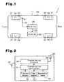
- a tire condition monitoring apparatus 1 according to an embodiment will now be described with reference to the drawings.
- the apparatus 1 is used in a vehicle such as an automobile.
- the receiver 40 is located at a predetermined position on the body frame 11 and is activated by electricity from a battery (not shown) of the vehicle 10.
- the receiver 40 is connected to a reception antenna 41 with a cable 42.
- the receiver 40 receives data transmitted by the transmitters 30 through the reception antenna 41.
- a display 50 is located in view of the driver of the vehicle 10, for example, in the passenger compartment.
- the display 50 is connected to the receiver 40 with a cable 43.
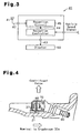
- each transmitter 30 has a transmitter controller 31, which is, for example, a microcomputer.
- the controller 31 includes, for example, a central processing unit (CPU), a read only memory (ROM), and a random access memory (RAM).
- a unique ID code is registered in an internal memory, for example, the ROM, of the controller 31. The ID code is used to distinguish the associated transmitter 30 from the other three transmitters 30.
- the tire pressure sensor 32 measures the air pressure in the interior of the associated tire 20 and provides the controller 31 with pressure data, which is obtained from the measurement.
- the temperature sensor 33 measures the temperature in the interior of the associated tire 20 and provides the transmission controller 31 with temperature data, which is obtained from the measurement.
- Each transmitter 30 is provided with a battery 37.
- the transmitter 30 is driven by electricity from the battery 37.
- the transmission controller 31 of each transmitter 30 controls the pressure sensor 32 and the temperature sensor 33 to perform measurement at predetermined time intervals (for example, every fifteen seconds). Also, the transmission controller 31 controls the transmission circuit 35 to perform periodic transmission every time the pressure sensor 32 completes a predetermined number of measurements (e.g., 40 cycles of measurements). Further, when detecting an abnormality in the pressure in the tire 20 or of the temperature in the tire 20, the controller 31 causes the transmission circuit 35 to perform transmission irrespective of timing of the periodic transmission.
- the timing of transmission of the transmitters 30 is regulated such that each transmitter 30 performs transmission at a.timing different from those of the other transmitters 30. Therefore, two or more of the transmitters 30 do not perform transmission simultaneously.
- the reception controller 44 receives a signal representing the speed of the vehicle 10, or a vehicle speed signal, from, for example, a speedometer (not shown) provided at a predetermined position in the vehicle 10.
- the reception circuit 45 receives data from the transmitters 30 through the reception antenna 41.
- the reception circuit 45 demodulates and decodes the received data and sends the data to the reception controller 44.
- the reception controller 44 corrects the air pressure data contained in the received data. Specifically, it obtains a correction value from the correction table on the basis of the vehicle speed signal to add and deduct the correction value thus obtained and the air pressure data received.
- a correction value obtained from the air pressure data received will be deducted.
- the reception controller 44 also causes the display 50 to show data regarding the air pressure and the temperature. Particularly, when there is an abnormality in the pressure of the tire 20, the controller 44 accordingly displays a warning on the display 50.
- the structure is arranged such that the air pressure of the tire 20 is measured with the pressure sensor 32, a main cause of error in the measurement of the air pressure is not possible in any component other than the diaphragm 32a of the pressure sensor 32.
- the speed of the vehicle 10 exceeds a predetermined speed
- the centrifugal force generated as the tire 20 rotates causes the tire 20 to elongate outwardly.
- the air pressure within the tire 20 lowers.
- the vehicle 10 is traveling, there occurs friction between the tire 20 and the road surface. This friction raises temperature within the tire 20. As a result, the air pressure within the tire 20 rises.
- This embodiment has the following advantages.
- the structure may be arranged such that an acceleration sensor 34 is provided in the transmitter 30 and in an internal memory of the transmission controller 31 such as, for example, a ROM, there is stored a correction table for correcting the air pressure data.
- the acceleration sensor 34 outputs data (centrifugal force data) of the centrifugal force generated as the tire 20 rotates to the transmission controller 31.
- the transmission controller 31 corrects the air pressure data on the basis of the centrifugal force data from the acceleration sensor 34 before wirelessly transmitting the data. Since the air pressure data is corrected by the transmitter 30 if constructed as described above, the air pressure data after the correction will be wirelessly transmitted to the receiver 40. Therefore, the receiver 40 is capable of displaying the data thus received on the display 50 immediately.
- the above-described acceleration sensor 34 is provided in the transmitter 30 and in the internal memory of the transmission controller 31 such as, for example, ROM, there is stored a correction table for correcting the air pressure data, the above-described embodiment may be applied. If constructed in this way, further accurate air pressure data will be able to be obtained.
- the structure may be arranged such that the pressure sensor 32 is disposed in such a manner that the direction of normal to the diaphragm 32a in the pressure sensor 32 is orthogonal to the direction of centrifugal force that is generated as the tire 20 rotates.
- a valve stem 60 for filling the tire 20 with air there has been disposed a casing 70 for housing the transmitter 30.
- Electronic components including the pressure sensor 32 are packaged on a substrate 80.
- the substrate 80 is arranged in such a manner that the direction of normal to the diaphragm 32a in the pressure sensor 32 is orthogonal to the direction of centrifugal force that is generated as the tire 20 rotates.
- the diaphragm 32a will be restrained from deflecting inwardly or outwardly due to centrifugal force that is generated as the tire 20 rotates. As a result, error will be reduced in air pressure from the pressure sensor 32. Accordingly, it will be possible to reduce measurement error due to the centrifugal force that is generated as the tire 20 rotates.
- the value of the correction table and the coefficient of the correction expression are preferably changed. In this respect, in the case of a change of several inches (for example, when changed from a 15-inch wheel 21 to a 17-inch wheel 21), it has been confirmed by experiment that it is within tolerance.
- the present invention may be applied to two-wheeled vehicles, such as bicycles and motor cycles, multi-wheeled busses, multi-wheeled trailers and industrial vehicles, such as forklifts.
- two-wheeled vehicles such as bicycles and motor cycles, multi-wheeled busses, multi-wheeled trailers and industrial vehicles, such as forklifts.
- the receiver 40 and the display 50 are provided in the tractor.
Landscapes
- Engineering & Computer Science (AREA)
- Mechanical Engineering (AREA)
- Measuring Fluid Pressure (AREA)
Claims (4)
- Récepteur pour un appareil (1) de surveillance de l'état de pneumatiques qui reçoit, au moyen d'une antenne (41) de réception montée sur un véhicule (10), des données en provenance d'un émetteur (30) qui transmet, sans fil, des données représentant une pression d'air du pneumatique (20) monté sur le véhicule (10), le récepteur traitant les données reçues et comprenant:des moyens (44) de correction de données reçues pour recevoir un signal représentant une vitesse du véhicule (10), destinés à corriger les données reçues représentant la pression d'air du pneumatique sur la base du signal représentant la vitesse du véhicule, caractérisé :en ce que les moyens (44) de correction de données reçues comprennent une table de correction qui contient une vitesse du véhicule (10) et une valeur de correction correspondant à la vitesse ;en ce que les moyens (44) de correction de données reçues obtiennent une valeur de correction à partir de la table de correction sur la base du signal de vitesse du véhicule dans le but d'ajouter et de soustraire la valeur de correction ainsi obtenue et les données de pression d'air reçues.
- Appareil de surveillance de l'état de pneumatiques, caractérisé par un émetteur (30) qui est monté à l'intérieur du pneumatique (20) d'un véhicule (10) et comprenant des moyens (32) de mesure pour mesurer une pression d'air du pneumatique (20), dans lequel l'émetteur (30) transmet, sans fil, des données représentant la pression d'air du pneumatique (20) mesurée par les moyens (32) de mesure, et le récepteur (40) de l'appareil (1) de surveillance de l'état de pneumatiques selon la revendication 1.
- Appareil de surveillance de l'état de pneumatiques selon la revendication 2, dans lequel l'émetteur (30) possède un code d'identification (ID) unique pour reconnaître l'émetteur (30) associé.
- Appareil de surveillance de l'état de pneumatiques selon la revendication 2, dans lequel les moyens (44) de correction de données reçues invalident les données représentant la condition du pneumatique (20) qui sont mesurées au cours d'un démarrage brutal ou d'un arrêt d'urgence du véhicule (10).
Applications Claiming Priority (2)
| Application Number | Priority Date | Filing Date | Title |
|---|---|---|---|
| JP2003279278 | 2003-07-24 | ||
| JP2003279278A JP2005043282A (ja) | 2003-07-24 | 2003-07-24 | タイヤ状態監視装置の送信機、タイヤ状態監視装置の受信機 |
Publications (2)
| Publication Number | Publication Date |
|---|---|
| EP1500528A1 EP1500528A1 (fr) | 2005-01-26 |
| EP1500528B1 true EP1500528B1 (fr) | 2006-04-26 |
Family
ID=33487712
Family Applications (1)
| Application Number | Title | Priority Date | Filing Date |
|---|---|---|---|
| EP04016798A Expired - Lifetime EP1500528B1 (fr) | 2003-07-24 | 2004-07-16 | Emetteur et récepteur pour appareil de surveillance de condition de pneumatique |
Country Status (4)
| Country | Link |
|---|---|
| US (1) | US7116217B2 (fr) |
| EP (1) | EP1500528B1 (fr) |
| JP (1) | JP2005043282A (fr) |
| DE (1) | DE602004000742D1 (fr) |
Families Citing this family (13)
| Publication number | Priority date | Publication date | Assignee | Title |
|---|---|---|---|---|
| US7429801B2 (en) * | 2002-05-10 | 2008-09-30 | Michelin Richerche Et Technique S.A. | System and method for generating electric power from a rotating tire's mechanical energy |
| US20050270148A1 (en) * | 2004-06-07 | 2005-12-08 | Calvin Modawell | Trailer tire monitoring system and method |
| US7348878B2 (en) * | 2005-09-29 | 2008-03-25 | International Truck Intellectual Property Company, Llc | Tire pressure monitoring system with permanent tire identification |
| JP2007107987A (ja) * | 2005-10-13 | 2007-04-26 | Pacific Ind Co Ltd | タイヤ状態監視装置 |
| JP4633642B2 (ja) * | 2006-02-06 | 2011-02-16 | 太平洋工業株式会社 | タイヤ圧検出装置及びタイヤ監視システム |
| US7541919B1 (en) * | 2006-08-21 | 2009-06-02 | Mobiletron Electronics Co., Ltd. | Wireless tire pressure and temperature detecting system |
| US7421902B2 (en) * | 2006-10-13 | 2008-09-09 | Smartire Systems, Inc. | Fluid pressure sensing method and apparatus |
| DE102006056965B4 (de) * | 2006-11-30 | 2008-09-04 | Continental Automotive Gmbh | Verfahren zur Lokalisierung von Radelektroniken |
| JP5127354B2 (ja) * | 2007-08-03 | 2013-01-23 | アルプス電気株式会社 | タイヤ情報監視装置及びタイヤ情報送信機 |
| FR2953765B1 (fr) * | 2009-12-15 | 2012-05-04 | Continental Automotive France | Procede et unite de mesure de pression de pneumatiques a vitesses superieures par un capteur integrant une couche de protection |
| DE102014101573B3 (de) | 2014-02-07 | 2014-10-09 | Vega Grieshaber Kg | Druckmessgerät mit automatischer Lagekorrektur |
| WO2021206023A1 (fr) * | 2020-04-10 | 2021-10-14 | アルプスアルパイン株式会社 | Dispositif et procédé de mesure d'usure de pneu |
| US12013299B1 (en) * | 2023-02-10 | 2024-06-18 | Atrion Medical Products, Inc. | Pressure guage attachment system and method of assembly |
Family Cites Families (6)
| Publication number | Priority date | Publication date | Assignee | Title |
|---|---|---|---|---|
| US4048614A (en) | 1975-08-18 | 1977-09-13 | Shumway Harry J | Low tire pressure warning device |
| DE3242291A1 (de) * | 1982-11-16 | 1984-05-17 | Moto Meter Ag, 7250 Leonberg | Vorrichtung zum messen des reifendrucks in luftreifen von fahrzeugen waehrend der fahrt |
| DE4303591C2 (de) | 1993-02-08 | 1996-02-22 | Alpha Beta Electronics Ag | Ventilkappe mit einer Einrichtung zur Erzeugung eines Druckanzeigesignals für einen mit einem Ventil ausgerüsteten Fahrzeugreifen |
| US6435020B1 (en) * | 1998-08-10 | 2002-08-20 | Continental Aktiengesellschaft | Method for allocating tire pressure control devices to wheel positions in a tire pressure control system of a motor vehicle |
| JP2001174357A (ja) | 1999-12-22 | 2001-06-29 | Pacific Ind Co Ltd | タイヤ空気圧センサー |
| US7100432B2 (en) * | 2002-06-06 | 2006-09-05 | Mineral Lassen Llc | Capacitive pressure sensor |
-
2003
- 2003-07-24 JP JP2003279278A patent/JP2005043282A/ja active Pending
-
2004
- 2004-07-16 DE DE602004000742T patent/DE602004000742D1/de not_active Expired - Lifetime
- 2004-07-16 EP EP04016798A patent/EP1500528B1/fr not_active Expired - Lifetime
- 2004-07-16 US US10/893,732 patent/US7116217B2/en not_active Expired - Fee Related
Also Published As
| Publication number | Publication date |
|---|---|
| DE602004000742D1 (de) | 2006-06-01 |
| EP1500528A1 (fr) | 2005-01-26 |
| US7116217B2 (en) | 2006-10-03 |
| US20050030169A1 (en) | 2005-02-10 |
| JP2005043282A (ja) | 2005-02-17 |
Similar Documents
| Publication | Publication Date | Title |
|---|---|---|
| US6983649B2 (en) | Tire condition monitoring apparatus | |
| EP1524133B1 (fr) | Emetteur pour un appareil de surveillance de condition de pneumatique | |
| US6963274B2 (en) | Transmitter of tire condition monitoring apparatus and tire condition monitoring apparatus | |
| US20040172179A1 (en) | Transmitter of tire condition monitoring apparatus and tire condition monitoring apparatus | |
| US6885292B2 (en) | Tire condition monitoring apparatus | |
| US9061662B2 (en) | Method and device for continuously determining wheel state variables of a wheel | |
| JP4213580B2 (ja) | 自動車のタイヤ圧力を監視するシステムと方法 | |
| EP1500528B1 (fr) | Emetteur et récepteur pour appareil de surveillance de condition de pneumatique | |
| KR20010061950A (ko) | 타이어에 영향을 주는 차량 상태를 감시하는 시스템 및 방법 | |
| EP1468847B1 (fr) | Appareil pour surveiller des conditions des pneus | |
| US7131323B2 (en) | Tire inflation pressure sensing apparatus with function of spare wheel identification | |
| US20040193340A1 (en) | Tire status monitoring apparatus | |
| EP1359029B1 (fr) | Système et méthode pour la surveillance de pression des pneumatiques | |
| US7352276B2 (en) | Casing structure of transmitter of tire condition monitoring apparatus | |
| US7187272B2 (en) | Casing structure of transmitter of tire condition monitoring apparatus | |
| KR100783960B1 (ko) | 타이어압력감지시스템(tpms)의 감지센서 위치 확인장치 및 방법 | |
| KR200450432Y1 (ko) | 타이어 공기압 측정용 압력센서 및 이를 구비한 타이어공기압 모니터링 시스템 | |
| CN120152891A (zh) | 用于基于车轮类型的车辆控制的系统和方法、空间节省式车轮、车辆以及计算机程序 |
Legal Events
| Date | Code | Title | Description |
|---|---|---|---|
| PUAI | Public reference made under article 153(3) epc to a published international application that has entered the european phase |
Free format text: ORIGINAL CODE: 0009012 |
|
| AK | Designated contracting states |
Kind code of ref document: A1 Designated state(s): AT BE BG CH CY CZ DE DK EE ES FI FR GB GR HU IE IT LI LU MC NL PL PT RO SE SI SK TR |
|
| AX | Request for extension of the european patent |
Extension state: AL HR LT LV MK |
|
| 17P | Request for examination filed |
Effective date: 20050125 |
|
| 17Q | First examination report despatched |
Effective date: 20050228 |
|
| GRAP | Despatch of communication of intention to grant a patent |
Free format text: ORIGINAL CODE: EPIDOSNIGR1 |
|
| AKX | Designation fees paid |
Designated state(s): DE FR GB |
|
| GRAS | Grant fee paid |
Free format text: ORIGINAL CODE: EPIDOSNIGR3 |
|
| GRAA | (expected) grant |
Free format text: ORIGINAL CODE: 0009210 |
|
| AK | Designated contracting states |
Kind code of ref document: B1 Designated state(s): DE FR GB |
|
| REG | Reference to a national code |
Ref country code: GB Ref legal event code: FG4D |
|
| REF | Corresponds to: |
Ref document number: 602004000742 Country of ref document: DE Date of ref document: 20060601 Kind code of ref document: P |
|
| PG25 | Lapsed in a contracting state [announced via postgrant information from national office to epo] |
Ref country code: DE Free format text: LAPSE BECAUSE OF FAILURE TO SUBMIT A TRANSLATION OF THE DESCRIPTION OR TO PAY THE FEE WITHIN THE PRESCRIBED TIME-LIMIT Effective date: 20060727 |
|
| PLBE | No opposition filed within time limit |
Free format text: ORIGINAL CODE: 0009261 |
|
| STAA | Information on the status of an ep patent application or granted ep patent |
Free format text: STATUS: NO OPPOSITION FILED WITHIN TIME LIMIT |
|
| 26N | No opposition filed |
Effective date: 20070129 |
|
| EN | Fr: translation not filed | ||
| PG25 | Lapsed in a contracting state [announced via postgrant information from national office to epo] |
Ref country code: FR Free format text: LAPSE BECAUSE OF FAILURE TO SUBMIT A TRANSLATION OF THE DESCRIPTION OR TO PAY THE FEE WITHIN THE PRESCRIBED TIME-LIMIT Effective date: 20070309 |
|
| PG25 | Lapsed in a contracting state [announced via postgrant information from national office to epo] |
Ref country code: FR Free format text: LAPSE BECAUSE OF FAILURE TO SUBMIT A TRANSLATION OF THE DESCRIPTION OR TO PAY THE FEE WITHIN THE PRESCRIBED TIME-LIMIT Effective date: 20060426 |
|
| GBPC | Gb: european patent ceased through non-payment of renewal fee |
Effective date: 20080716 |
|
| PG25 | Lapsed in a contracting state [announced via postgrant information from national office to epo] |
Ref country code: GB Free format text: LAPSE BECAUSE OF NON-PAYMENT OF DUE FEES Effective date: 20080716 |