EP1500529A1 - Suspension d'essieu rigide pour vehicules - Google Patents
Suspension d'essieu rigide pour vehicules Download PDFInfo
- Publication number
- EP1500529A1 EP1500529A1 EP04015013A EP04015013A EP1500529A1 EP 1500529 A1 EP1500529 A1 EP 1500529A1 EP 04015013 A EP04015013 A EP 04015013A EP 04015013 A EP04015013 A EP 04015013A EP 1500529 A1 EP1500529 A1 EP 1500529A1
- Authority
- EP
- European Patent Office
- Prior art keywords
- bracket
- stop buffer
- axle
- hole
- recess
- Prior art date
- Legal status (The legal status is an assumption and is not a legal conclusion. Google has not performed a legal analysis and makes no representation as to the accuracy of the status listed.)
- Granted
Links
Images

Classifications
-
- B—PERFORMING OPERATIONS; TRANSPORTING
- B60—VEHICLES IN GENERAL
- B60G—VEHICLE SUSPENSION ARRANGEMENTS
- B60G11/00—Resilient suspensions characterised by arrangement, location or kind of springs
- B60G11/02—Resilient suspensions characterised by arrangement, location or kind of springs having leaf springs only
- B60G11/10—Resilient suspensions characterised by arrangement, location or kind of springs having leaf springs only characterised by means specially adapted for attaching the spring to axle or sprung part of the vehicle
-
- B—PERFORMING OPERATIONS; TRANSPORTING
- B60—VEHICLES IN GENERAL
- B60G—VEHICLE SUSPENSION ARRANGEMENTS
- B60G11/00—Resilient suspensions characterised by arrangement, location or kind of springs
- B60G11/32—Resilient suspensions characterised by arrangement, location or kind of springs having springs of different kinds
- B60G11/34—Resilient suspensions characterised by arrangement, location or kind of springs having springs of different kinds including leaf springs
- B60G11/38—Resilient suspensions characterised by arrangement, location or kind of springs having springs of different kinds including leaf springs and also rubber springs
- B60G11/40—Resilient suspensions characterised by arrangement, location or kind of springs having springs of different kinds including leaf springs and also rubber springs the rubber springs being attached to the axle
-
- B—PERFORMING OPERATIONS; TRANSPORTING
- B60—VEHICLES IN GENERAL
- B60G—VEHICLE SUSPENSION ARRANGEMENTS
- B60G7/00—Pivoted suspension arms; Accessories thereof
- B60G7/04—Buffer means for limiting movement of arms
-
- B—PERFORMING OPERATIONS; TRANSPORTING
- B60—VEHICLES IN GENERAL
- B60G—VEHICLE SUSPENSION ARRANGEMENTS
- B60G9/00—Resilient suspensions of a rigid axle or axle housing for two or more wheels
- B60G9/003—Resilient suspensions of a rigid axle or axle housing for two or more wheels the axle being rigidly connected to a trailing guiding device
-
- B—PERFORMING OPERATIONS; TRANSPORTING
- B60—VEHICLES IN GENERAL
- B60G—VEHICLE SUSPENSION ARRANGEMENTS
- B60G2202/00—Indexing codes relating to the type of spring, damper or actuator
- B60G2202/10—Type of spring
- B60G2202/11—Leaf spring
- B60G2202/112—Leaf spring longitudinally arranged
-
- B—PERFORMING OPERATIONS; TRANSPORTING
- B60—VEHICLES IN GENERAL
- B60G—VEHICLE SUSPENSION ARRANGEMENTS
- B60G2204/00—Indexing codes related to suspensions per se or to auxiliary parts
- B60G2204/40—Auxiliary suspension parts; Adjustment of suspensions
- B60G2204/45—Stops limiting travel
- B60G2204/4502—Stops limiting travel using resilient buffer
Definitions
- the invention relates to a sprung suspension of a rigid axle in a motor vehicle with Characteristics as indicated in the preamble of claim 1.
- a sprung axle suspension of the generic type is already in Bentley vehicles the years of construction were used until 1934, as evidenced by corresponding vintage cars is.
- the bump stop is a square, about two centimeters thick Disc of limited elastic material for application, presumably in the recess the console is vulcanised or glued.
- the actual connection type is at said Oldtimers but not detectable.
- stop buffer quick and easy to attach to the console.
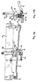
- a portion of a vehicle is a part of the Chassis forming frame longitudinal member 1 shown on which a rigid axle with her Axle body 2 is sprung hinged and fixed, by means of a leaf spring 3, the off a single spring leaf or a leaf spring package can exist.
- the leaf spring 3 is attached one end with its spring eye 4 to a frame-fixed bracket 5 and with its other given spring eye 6 on a rocker 7 and flying over this hinged to a frame fixed bearing block 8.
- With 9 is a shock absorber and with 10 a Designated stabilizer, both on the one hand on the axle body 2 and on the other hand on the frame longitudinal member 1 hinged.
- the axle body 2 of the rigid axle is at the bottom of the leaf spring 3 fitting by means of two U-shaped headband 11, 12 attached. These overlap one resting on top of the leaf spring 3 Console 13 and tension it there by means of down on the axle 2 supporting Nuts 14 tight.
- the console 13 has a recess 15 at the top, in which a stop buffer 16 is included in the deflection of the frame in relation to the rigid axle in cooperation with a frame-fixed stop 17 limits the Einfederungsweg.
- one cross channel 18, 19 is given in the console 13 on both sides of its recess 15, in each of the two brackets 11, 12 is fixed in position added.
- this stop buffer 16 is used as a stop buffer 16 such that a buffer body 20th and at the bottom of this a mushroom-shaped fastening pin 21, whose neck with 22 and head 23 are designated.
- this stop buffer 16 according to the invention with a lower portion 24 of its buffer body 20 in the correspondingly formed immersed upper recess 15 of the console 13 added. Furthermore penetrates this stop buffer 16 according to the invention with the neck 22 of its mushroom-shaped fastening pin 21 a through hole 25 in the console 13 and dives with the head 23rd his attachment pin 21 in a given below in the console 13 recess 26 a and there is at the bottom 27, the edge of the through-hole 25 behind, locked.
- the underside 28 of the buffer body 20 can be made the stop buffer 16 slightly conical or convex and the bottom 29 of the upper Deepening 15 in the console 13 for a positive engagement of such thus designed buffer body bottom 28 adapted accordingly.
- the stop buffer 16 has at least in that lower region 24, with which he in the upper Deepening 15 of the console 15 is immersed, a circular cylindrical cross-section, to which the mushroom-shaped fastening pin 21 is arranged coaxially.
- the through hole 25 in the bracket 13 is up to the bottom 29 of the upper recess 15 tapered or strongly rounded, which is a perfect and damage-free Inserting the mushroom-shaped fastening pin 21 on the stop buffer 16 at its mounting on the console 13 favors.
- the neck 22 of the mushroom-shaped attachment pin 21 on the stop buffer 16 has a slightly, z. B. a few tenths of a millimeter, smaller diameter than the through hole 25 in the console 13 and a length equal to the distance of the bottoms 27, 29 of the two Recesses 15, 16 in the console 23 and the thickness of the given therebetween Wall 30 is equal to or a few tenths of a millimeter larger than this (r).
- the stop buffer 16 is made of limited elastic material, for. B. hard rubber or a suitable plastic.
- the head 23 of the mushroom-shaped fastening pin 21 has a relation to that of the Halses 22 of such a larger diameter, that it due to the flexibility of the stop buffer material when mounting the stop buffer 16 on the console 13 during penetration the through hole 25 is first compressible to the diameter and Then, after complete penetration of the through hole 25, again on his can expand in the locking position given normal diameter.
- the head 23 of the mushroom-shaped fastening pin 21 tapers from its upper largest diameter at 31 starting conical with either straight or concave curved outer surface 32 to a smaller diameter at its end face 33rd towards, by a certain amount smaller than the diameter of the through hole 25 in the console 13 is.
- the console 13 may - as shown - be formed in cross-section approximately hat-shaped, wherein in its elevated central region 34, the upper recess 15 open at the top and the lower Recess 26 are formed open at the bottom. On both sides of this elevated middle area 34 join side portions 35, 36 of a base plate 37 in the top the transverse grooves 18, 19 are formed for receiving the retaining clip 11, 12.
- the upper Recess 15 in the example shown is slightly larger in diameter than the immersed in it lower portion 24 of the stop buffer and also slightly larger than the width of the increased central region 34, so that the recess 15 is not completely closed.
- stop buffer 16 The connection of stop buffer 16 and console 13 can be controlled by hand or robot respectively.
- the stop buffer 16 is brought from above to the console 13 and then in the axial direction of the fungal attachment pin 21 with his head 23rd pressed through the through hole 25.
- the stop buffer 16 with his Bottom 28 is seated on the bottom 29 of the upper recess 15 in the console 13, relaxed the previously compressed in the through hole 25 head 23 back on his given at 31 normal diameter, so that a certain margin around the Through hole 25 at the bottom 27 of the lower recess 26 in the console of the head 23rd is engaged behind and thereby the stop buffer 16 is fixedly mounted on the console 13.
Landscapes
- Engineering & Computer Science (AREA)
- Mechanical Engineering (AREA)
- Vehicle Body Suspensions (AREA)
- Vibration Prevention Devices (AREA)
- Vibration Dampers (AREA)
- Springs (AREA)
Applications Claiming Priority (2)
| Application Number | Priority Date | Filing Date | Title |
|---|---|---|---|
| AT0114003A AT500146B1 (de) | 2003-07-21 | 2003-07-21 | Gefederte aufhängung einer starrachse in einem fahrzeug |
| AT11402003 | 2003-07-21 |
Publications (2)
| Publication Number | Publication Date |
|---|---|
| EP1500529A1 true EP1500529A1 (fr) | 2005-01-26 |
| EP1500529B1 EP1500529B1 (fr) | 2007-11-14 |
Family
ID=33479921
Family Applications (1)
| Application Number | Title | Priority Date | Filing Date |
|---|---|---|---|
| EP04015013A Expired - Lifetime EP1500529B1 (fr) | 2003-07-21 | 2004-06-25 | Suspension d'essieu rigide pour vehicules |
Country Status (3)
| Country | Link |
|---|---|
| EP (1) | EP1500529B1 (fr) |
| AT (2) | AT500146B1 (fr) |
| DE (1) | DE502004005469D1 (fr) |
Cited By (3)
| Publication number | Priority date | Publication date | Assignee | Title |
|---|---|---|---|---|
| AT503614B1 (de) * | 2006-02-27 | 2008-07-15 | Man Nutzfahrzeuge Oesterreich | Anschlag zur begrenzung des s-schlags einer blattfeder |
| EP3121036A1 (fr) * | 2015-07-23 | 2017-01-25 | Iveco Magirus Ag | Suspension d'essieu pneumatique pour un essieu arrière de véhicule |
| CN110588267A (zh) * | 2019-08-22 | 2019-12-20 | 金龙联合汽车工业(苏州)有限公司 | 一种板弹簧复合盖板 |
Citations (5)
| Publication number | Priority date | Publication date | Assignee | Title |
|---|---|---|---|---|
| US2942870A (en) * | 1957-05-04 | 1960-06-28 | Morris Motors Ltd | Motor vehicle axle mountings |
| JPS5599405A (en) * | 1979-01-22 | 1980-07-29 | Shin Meiwa Ind Co Ltd | Device for controlling strain of suspension spring of vehicle |
| EP1088687A1 (fr) * | 1999-09-29 | 2001-04-04 | Weweler Nederland B.V. | Connexion entre un essieu de roue de véhicule et un bras de suspension portant l' essieu de roue |
| US20030025288A1 (en) * | 2001-08-06 | 2003-02-06 | Louie Petit | Air cushion suspension assembly for use with over the road trucks |
| US20030038445A1 (en) * | 2001-08-01 | 2003-02-27 | Sutton Anthony D. | Symbiotic elastomeric non-linear spring device for mobile vehicle suspension system |
Family Cites Families (4)
| Publication number | Priority date | Publication date | Assignee | Title |
|---|---|---|---|---|
| US4083545A (en) * | 1976-08-31 | 1978-04-11 | Trw Inc. | Spring shackle assembly |
| JPH06241260A (ja) * | 1993-02-19 | 1994-08-30 | Nippon Mektron Ltd | バンプストッパ− |
| JPH09272317A (ja) * | 1996-04-10 | 1997-10-21 | Shinko Seisakusho:Kk | バンプストッパ装置 |
| JPH10217730A (ja) * | 1997-01-31 | 1998-08-18 | Suzuki Motor Corp | 車両用バンプストッパ構造 |
-
2003
- 2003-07-21 AT AT0114003A patent/AT500146B1/de not_active IP Right Cessation
-
2004
- 2004-06-25 DE DE502004005469T patent/DE502004005469D1/de not_active Expired - Lifetime
- 2004-06-25 AT AT04015013T patent/ATE378203T1/de active
- 2004-06-25 EP EP04015013A patent/EP1500529B1/fr not_active Expired - Lifetime
Patent Citations (5)
| Publication number | Priority date | Publication date | Assignee | Title |
|---|---|---|---|---|
| US2942870A (en) * | 1957-05-04 | 1960-06-28 | Morris Motors Ltd | Motor vehicle axle mountings |
| JPS5599405A (en) * | 1979-01-22 | 1980-07-29 | Shin Meiwa Ind Co Ltd | Device for controlling strain of suspension spring of vehicle |
| EP1088687A1 (fr) * | 1999-09-29 | 2001-04-04 | Weweler Nederland B.V. | Connexion entre un essieu de roue de véhicule et un bras de suspension portant l' essieu de roue |
| US20030038445A1 (en) * | 2001-08-01 | 2003-02-27 | Sutton Anthony D. | Symbiotic elastomeric non-linear spring device for mobile vehicle suspension system |
| US20030025288A1 (en) * | 2001-08-06 | 2003-02-06 | Louie Petit | Air cushion suspension assembly for use with over the road trucks |
Non-Patent Citations (1)
| Title |
|---|
| PATENT ABSTRACTS OF JAPAN vol. 0041, no. 47 (M - 036) 16 October 1980 (1980-10-16) * |
Cited By (8)
| Publication number | Priority date | Publication date | Assignee | Title |
|---|---|---|---|---|
| AT503614B1 (de) * | 2006-02-27 | 2008-07-15 | Man Nutzfahrzeuge Oesterreich | Anschlag zur begrenzung des s-schlags einer blattfeder |
| EP3121036A1 (fr) * | 2015-07-23 | 2017-01-25 | Iveco Magirus Ag | Suspension d'essieu pneumatique pour un essieu arrière de véhicule |
| WO2017013261A1 (fr) * | 2015-07-23 | 2017-01-26 | Iveco Magirus Ag | Suspension d'essieu pneumatique pour essieu arrière d'un véhicule |
| CN107848356A (zh) * | 2015-07-23 | 2018-03-27 | 依维柯马基路斯公司 | 用于车辆的后车桥的气动式车桥悬架 |
| RU2713263C2 (ru) * | 2015-07-23 | 2020-02-04 | Ивеко Магирус Аг | Пневматическая подвеска оси для задней оси транспортного средства |
| AU2016296919B2 (en) * | 2015-07-23 | 2020-02-27 | Iveco Magirus Ag | Pneumatic axle suspension for a rear axle of a vehicle |
| CN107848356B (zh) * | 2015-07-23 | 2020-10-16 | 依维柯马基路斯公司 | 用于车辆的后车桥的气动式车桥悬架 |
| CN110588267A (zh) * | 2019-08-22 | 2019-12-20 | 金龙联合汽车工业(苏州)有限公司 | 一种板弹簧复合盖板 |
Also Published As
| Publication number | Publication date |
|---|---|
| EP1500529B1 (fr) | 2007-11-14 |
| ATE378203T1 (de) | 2007-11-15 |
| AT500146A1 (de) | 2005-11-15 |
| DE502004005469D1 (de) | 2007-12-27 |
| AT500146B1 (de) | 2007-07-15 |
Similar Documents
| Publication | Publication Date | Title |
|---|---|---|
| EP2125425B1 (fr) | Siège de véhicule et procédé de montage | |
| DE3608898C2 (fr) | ||
| DE29906013U1 (de) | Innenrückblickspiegel für Fahrzeuge, insbesondere für Kraftfahrzeuge | |
| DE3918802A1 (de) | Schmutzfaengerbefestigung | |
| EP0853566A1 (fr) | Lame d'essuie-glace pour les vitres de vehicules a moteur | |
| DE19929914B4 (de) | Wischarm | |
| DE102015215592A1 (de) | Fahrzeugsitz | |
| DE2919960C2 (fr) | ||
| EP2776248A2 (fr) | Racle de serigraphie et dispositif de serigraphie | |
| EP0853564A1 (fr) | Lame d'essuie-glace pour vehicules a moteur | |
| DE10043802A1 (de) | Achse für Fahrzeuge, insbesondere Nutzfahrzeuge | |
| DE69303107T2 (de) | Scheibenwischanlage mit Windableiter | |
| DE69310883T2 (de) | Kraftfahrzeugstossfängerbefestigung | |
| EP1500529B1 (fr) | Suspension d'essieu rigide pour vehicules | |
| DE2342365C3 (de) | Schmutzfänger | |
| DE19721757C1 (de) | Vorrichtung zur Befestigung von Anbauteilen | |
| WO2012025326A1 (fr) | Élément porte-balai d'essuie-glace comportant une attache intégrée pour bras d'essuie-glace | |
| DE102004029740A1 (de) | Verfahren zur Montage eines Panoramadachs an einem Kraftfahrzeug sowie entsprechend hergestelltes Kraftfahrzeug mit Panoramadach | |
| DE102012014667A1 (de) | Stützvorrichtung für einen Sitz und damit ausgerüsteter Fahrzeugsitz | |
| DE102017003838A1 (de) | Anordnung zum Montieren eines Stützquerträgers zwischen einem ersten Bauteil und einem gegenüberliegenden zweiten Bauteil eines Fahrzeugs | |
| DE102015014307B4 (de) | Befestigungsvorrichtung zum Anbauen einer Luftleitvorrichtung an einer Fahrzeugkarosserie und Fahrzeug | |
| DE69404908T2 (de) | Scheibenwischer mit gelenkig verbundenen Elementen | |
| DE19931173B4 (de) | Fahrzeugteil, vorzugsweise Kraftfahrzeugdach sowie Verfahren zum Verschrauben von Halteböcken in Schweißkanälen eines solchen Fahrzeugteiles | |
| DE102017008719A1 (de) | Halteanordnung zur Befestigung einer Unterbodenverkleidung an einer Bodenstruktur eines Kraftwagens und Verfahren zur Befestigung einer solchen Unterbodenverkleidung | |
| DE8308142U1 (de) | Wischvorrichtung fuer scheiben von kraftfahrzeugen |
Legal Events
| Date | Code | Title | Description |
|---|---|---|---|
| REG | Reference to a national code |
Ref country code: SE Ref legal event code: TRGR |
|
| PUAI | Public reference made under article 153(3) epc to a published international application that has entered the european phase |
Free format text: ORIGINAL CODE: 0009012 |
|
| 17P | Request for examination filed |
Effective date: 20041117 |
|
| AK | Designated contracting states |
Kind code of ref document: A1 Designated state(s): AT BE BG CH CY CZ DE DK EE ES FI FR GB GR HU IE IT LI LU MC NL PL PT RO SE SI SK TR |
|
| AX | Request for extension of the european patent |
Extension state: AL HR LT LV MK |
|
| RAP1 | Party data changed (applicant data changed or rights of an application transferred) |
Owner name: MAN NUTZFAHRZEUGE OESTERREICH AG |
|
| AKX | Designation fees paid |
Designated state(s): AT DE FR IT SE |
|
| GRAP | Despatch of communication of intention to grant a patent |
Free format text: ORIGINAL CODE: EPIDOSNIGR1 |
|
| GRAS | Grant fee paid |
Free format text: ORIGINAL CODE: EPIDOSNIGR3 |
|
| GRAA | (expected) grant |
Free format text: ORIGINAL CODE: 0009210 |
|
| AK | Designated contracting states |
Kind code of ref document: B1 Designated state(s): AT DE FR IT SE |
|
| REF | Corresponds to: |
Ref document number: 502004005469 Country of ref document: DE Date of ref document: 20071227 Kind code of ref document: P |
|
| ET | Fr: translation filed | ||
| PLBE | No opposition filed within time limit |
Free format text: ORIGINAL CODE: 0009261 |
|
| STAA | Information on the status of an ep patent application or granted ep patent |
Free format text: STATUS: NO OPPOSITION FILED WITHIN TIME LIMIT |
|
| 26N | No opposition filed |
Effective date: 20080815 |
|
| REG | Reference to a national code |
Ref country code: DE Ref legal event code: R081 Ref document number: 502004005469 Country of ref document: DE Owner name: MAN TRUCK & BUS OESTERREICH AG, AT Free format text: FORMER OWNER: MAN NUTZFAHRZEUGE OESTERREICH AG, STEYR, AT Effective date: 20120125 Ref country code: DE Ref legal event code: R081 Ref document number: 502004005469 Country of ref document: DE Owner name: MAN TRUCK BUS OESTERREICH AG, AT Free format text: FORMER OWNER: MAN NUTZFAHRZEUGE OESTERREICH AG, STEYR, AT Effective date: 20120125 |
|
| REG | Reference to a national code |
Ref country code: FR Ref legal event code: CD Owner name: MAN TRUCK & BUS OSTERREICH AG Effective date: 20120314 |
|
| REG | Reference to a national code |
Ref country code: AT Ref legal event code: HC Ref document number: 378203 Country of ref document: AT Kind code of ref document: T Owner name: MAN TRUCK & BUS OESTERREICH AG, AT Effective date: 20120530 |
|
| REG | Reference to a national code |
Ref country code: FR Ref legal event code: PLFP Year of fee payment: 13 |
|
| REG | Reference to a national code |
Ref country code: FR Ref legal event code: PLFP Year of fee payment: 14 |
|
| REG | Reference to a national code |
Ref country code: FR Ref legal event code: PLFP Year of fee payment: 15 |
|
| REG | Reference to a national code |
Ref country code: DE Ref legal event code: R081 Ref document number: 502004005469 Country of ref document: DE Owner name: MAN TRUCK & BUS SE, DE Free format text: FORMER OWNER: MAN TRUCK & BUS OESTERREICH AG, STEYR, AT |
|
| REG | Reference to a national code |
Ref country code: AT Ref legal event code: PC Ref document number: 378203 Country of ref document: AT Kind code of ref document: T Owner name: MAN TRUCK & BUS SE, DE Effective date: 20211123 |
|
| PGFP | Annual fee paid to national office [announced via postgrant information from national office to epo] |
Ref country code: SE Payment date: 20230317 Year of fee payment: 20 |
|
| PGFP | Annual fee paid to national office [announced via postgrant information from national office to epo] |
Ref country code: FR Payment date: 20230622 Year of fee payment: 20 Ref country code: DE Payment date: 20230627 Year of fee payment: 20 |
|
| PGFP | Annual fee paid to national office [announced via postgrant information from national office to epo] |
Ref country code: AT Payment date: 20230619 Year of fee payment: 20 |
|
| PGFP | Annual fee paid to national office [announced via postgrant information from national office to epo] |
Ref country code: IT Payment date: 20230620 Year of fee payment: 20 |
|
| REG | Reference to a national code |
Ref country code: DE Ref legal event code: R071 Ref document number: 502004005469 Country of ref document: DE |
|
| REG | Reference to a national code |
Ref country code: SE Ref legal event code: EUG |
|
| REG | Reference to a national code |
Ref country code: AT Ref legal event code: MK07 Ref document number: 378203 Country of ref document: AT Kind code of ref document: T Effective date: 20240625 |