EP1500530B1 - Suspension d'essieu rigide pour véhicules avec capture de resort - Google Patents
Suspension d'essieu rigide pour véhicules avec capture de resort Download PDFInfo
- Publication number
- EP1500530B1 EP1500530B1 EP04015012A EP04015012A EP1500530B1 EP 1500530 B1 EP1500530 B1 EP 1500530B1 EP 04015012 A EP04015012 A EP 04015012A EP 04015012 A EP04015012 A EP 04015012A EP 1500530 B1 EP1500530 B1 EP 1500530B1
- Authority
- EP
- European Patent Office
- Prior art keywords
- rocker
- retaining
- bearing block
- spring
- retaining pin
- Prior art date
- Legal status (The legal status is an assumption and is not a legal conclusion. Google has not performed a legal analysis and makes no representation as to the accuracy of the status listed.)
- Expired - Lifetime
Links
Images

Classifications
-
- B—PERFORMING OPERATIONS; TRANSPORTING
- B60—VEHICLES IN GENERAL
- B60G—VEHICLE SUSPENSION ARRANGEMENTS
- B60G7/00—Pivoted suspension arms; Accessories thereof
- B60G7/04—Buffer means for limiting movement of arms
-
- B—PERFORMING OPERATIONS; TRANSPORTING
- B60—VEHICLES IN GENERAL
- B60G—VEHICLE SUSPENSION ARRANGEMENTS
- B60G11/00—Resilient suspensions characterised by arrangement, location or kind of springs
- B60G11/02—Resilient suspensions characterised by arrangement, location or kind of springs having leaf springs only
- B60G11/04—Resilient suspensions characterised by arrangement, location or kind of springs having leaf springs only arranged substantially parallel to the longitudinal axis of the vehicle
-
- B—PERFORMING OPERATIONS; TRANSPORTING
- B60—VEHICLES IN GENERAL
- B60G—VEHICLE SUSPENSION ARRANGEMENTS
- B60G11/00—Resilient suspensions characterised by arrangement, location or kind of springs
- B60G11/02—Resilient suspensions characterised by arrangement, location or kind of springs having leaf springs only
- B60G11/10—Resilient suspensions characterised by arrangement, location or kind of springs having leaf springs only characterised by means specially adapted for attaching the spring to axle or sprung part of the vehicle
- B60G11/12—Links, pins, or bushes
-
- B—PERFORMING OPERATIONS; TRANSPORTING
- B60—VEHICLES IN GENERAL
- B60G—VEHICLE SUSPENSION ARRANGEMENTS
- B60G2202/00—Indexing codes relating to the type of spring, damper or actuator
- B60G2202/10—Type of spring
- B60G2202/11—Leaf spring
- B60G2202/112—Leaf spring longitudinally arranged
-
- B—PERFORMING OPERATIONS; TRANSPORTING
- B60—VEHICLES IN GENERAL
- B60G—VEHICLE SUSPENSION ARRANGEMENTS
- B60G2204/00—Indexing codes related to suspensions per se or to auxiliary parts
- B60G2204/10—Mounting of suspension elements
- B60G2204/12—Mounting of springs or dampers
- B60G2204/121—Mounting of leaf springs
-
- B—PERFORMING OPERATIONS; TRANSPORTING
- B60—VEHICLES IN GENERAL
- B60G—VEHICLE SUSPENSION ARRANGEMENTS
- B60G2204/00—Indexing codes related to suspensions per se or to auxiliary parts
- B60G2204/40—Auxiliary suspension parts; Adjustment of suspensions
- B60G2204/43—Fittings, brackets or knuckles
-
- B—PERFORMING OPERATIONS; TRANSPORTING
- B60—VEHICLES IN GENERAL
- B60G—VEHICLE SUSPENSION ARRANGEMENTS
- B60G2204/00—Indexing codes related to suspensions per se or to auxiliary parts
- B60G2204/40—Auxiliary suspension parts; Adjustment of suspensions
- B60G2204/45—Stops limiting travel
Definitions
- the invention relates to a sprung suspension of a rigid axle on the chassis frame of a vehicle, in particular trucks or buses, with features specified in the preamble of claim 1 Art.
- the invention is based on a sprung suspension of a rigid axle as from GB 1202482 A known.
- a leaf spring is hinged to the front of a frame-fixed bracket and the rear of a lower bearing point of a rocker.
- the rocker itself is hinged in its upper part to a frame fixed bearing block.
- the rocker is one - associated with the breakage of the leaf spring - spring catch device assigned.
- This has a rear bearing block spaced from the upper swing bearing point and shifted down rear catch bolt, on which the rocker comes in the event of a spring break with its rear edge approximately centrally to the plant.
- This known solution therefore requires a downwardly extended and correspondingly widened bearing block for the mounting of the rocker and suitable arrangement of the catch bolt.
- the spring catch device according to the invention is immediately effective when the leaf spring breaks at its front attachment point.
- the leaf spring shifts in this case to the rear.
- this movement is stopped after a short way, because the deflected backward at this longitudinal displacement rocker comes after a short angular movement with the stop surface at its catching area on the bearing block fixed catch bolt to the plant.
- the axle of the rigid axle although a bit crooked, that is, no longer perpendicular to the vehicle longitudinal axis, but this disadvantage can be compensated for slower driving on the wheel steering.
- the safety gear according to the invention does not interfere with the deflection of the chassis frame to the axis, since in this case the rocker is not swung back to the extent of the fraction of the spring.
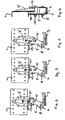
- FIG. 5 There is a vehicle, z. As trucks or buses, a portion of a part of the chassis forming frame side member 1 shown on which a rigid axle with its axle 2 is sprung articulated and fixed. This purpose is served by either a single spring leaf or a leaf spring package existing leaf spring 3, which is fastened with its front spring eye 4 on a frame-fixed front bearing block 5 and with its rear spring eye 6 on a rocker 7, where the lower bearing 8, hinged and this rocker 7 suspended on a rear frame fixed bearing block 9, wherein the upper bearing point on the rocker 7, with which the connection is made to the bearing block 9, designated 10.
- a shock absorber 11 which is articulated at the top on a frame-fixed bearing block 12 and at the bottom of the axle 2, and a U-shaped stabilizer 13, with its transverse leg on the axle body 2 and with its two U-shaped stabilizer. Legs is hinged to one holding rod 14, which is suspended with its upper end to a frame-fixed block 15. 16 with a stop buffer is designated, which is fastened on top of the leaf spring 3 and in cooperation with a frame-fixed stop surface 17, the Einfederungsweg of the frame 1 with respect to the axle beam 2 limited.
- a correspondingly modified rocker and modified rear bearing block is used in the region of the rear linkage of the leaf spring 3.
- the rocker according to the invention is denoted by 7 'and the rear bearing block according to the invention is denoted by 9'.
- These two components 7 ', 9' are used to form the spring catch device according to the invention, namely as follows.
- a catch pin 18 is arranged above and spaced from the upper bearing point 10 for the rocker 7'.
- the rocker 7 'seen from the upper bearing 10 is extended upwards to the area of the catch bolt 18 by a catching area 19 and has at least one stop surface 20 at this catch area 19 in the amount of the catch bolt 18.
- a stop surface 20 is provided, which is given by a section on a - viewed forwardly in the direction of travel - front end face on the catch portion 19 of the rocker 7 ', which stop surface 20 engages behind the catch pin 18.
- two abutment surfaces namely a rear abutment surface 20 and a front abutment surface 21, are provided on or in the catching region 19 of the rocker 7 '.
- this is provided in the catching area 19 of the rocker 7 'a slot or a transverse bore with respect to the diameter of the catch bolt 18 corresponding larger diameter, in which slot or transverse bore of the catch pin 18 dips and whose or front and rear arcuate wall portion, the front and rear abutment surface 20, 21 form.
- an upwardly open mouth is provided on the catching area 19 of the rocker 7 ', whose front and rear boundary surfaces form the front and rear abutment surfaces 20, 21.
- Two abutment surfaces 20, 21 have the advantage that when broken leaf spring 3 not only a forward drive, but on a reverse driving with each set on the frame-side stop leaf spring 3 is possible.
- the catch bolt 18 may be formed for example by a cylindrical steel bolt, which penetrates a transverse bore in the rear bearing block 9 ', this inside and outside outstanding and on the bearing block 9' is welded.
- the rocker 7 ' can be formed, for example, by two identical and mutually parallel tabs - see FIG. 4 - which are held at a parallel distance via a spacer sleeve within the front spring eye 6 and a spacer sleeve 22 at the rear bearing block 9'.
Landscapes
- Engineering & Computer Science (AREA)
- Mechanical Engineering (AREA)
- Vehicle Body Suspensions (AREA)
- Body Structure For Vehicles (AREA)
Claims (6)
- Suspension amortie d'un essieu rigide sur le cadre de châssis d'un véhicule, en particulier d'un camion ou d'un bus, auquel cas le corps d'essieu (2) est fixé par le dessous sur un ressort à lame (3) qui est articulé à l'avant sur un support de palier (5) fixé sur le cadre et à l'arrière sur un point d'appui inférieur (8) d'un bras oscillant (7) qui est à son tour articulé de manière pivotable sur un support de palier arrière (9) fixé sur le cadre par le biais d'un point d'appui supérieur (10) et un dispositif de retenue de ressort - devenant efficace au niveau de sa zone de fixation avant (4) en cas de rupture du ressort à lame (3) - qui présente une douille de retenue (18) disposée sur le support de palier arrière (9) à une certaine distance du point d'appui supérieur (10) du bras d'oscillant (7), douille sur laquelle le bras oscillant (7) vient en appui à l'aide d'au moins une surface de butée en cas de rupture de ressort, mais reste à une certaine distance à une cote plus ou moins grande de la douille de retenue (18) dans chaque état de débattement du cadre (1) en référence au corps d'essieu (2) en cas de ressorts à lames intacts, caractérisée en ce que la douille de retenue (18) est disposée sur le support de palier arrière (9') au-dessus et à une certaine distance du point d'appui supérieur (10) du bras oscillant (7'), en ce que le bras oscillant (7') est prolongé d'une partie de retenue (19) vers le haut jusqu'au niveau de la douille de retenue (18) et en ce que, au niveau de la partie de retenue (19) du bras oscillant (7'), au moins une surface de butée (20, 21) est disposée à hauteur de la douille de retenue (18).
- Suspension selon la revendication 1, caractérisée en ce que seule une surface de butée est prévue et celle-ci existe par une découpe sur une surface frontale avant - vue vers l'avant dans le sens de la marche - au niveau de la partie de retenue (19) du bras oscillant (7') dont la surface de butée (20) vient en prise derrière la douille de retenue (18).
- Suspension selon la revendication 1, caractérisée en ce que deux surfaces de butée (20, 21), à savoir une arrière (20) et une avant (21), sont prévues au niveau ou dans la partie de retenue (19) du bras oscillant (7').
- Suspension selon la revendication 3, caractérisée en ce que, dans la partie de retenue (19) du bras oscillant (7') est prévu un trou long ou un alésage transversal avec un diamètre plus important par rapport au diamètre de la douille de retenue (18), dans lequel est enfoncée la douille de retenue (18) et dont la découpe de paroi avant et arrière forment les surfaces de butée (20 ,21).
- Suspension selon la revendication 3, caractérisée en ce que, au niveau de la partie de retenue (19) du bras oscillant (7') est prévue un bec ouvert vers le haut dont les surfaces de délimitation avant et arrière forment les deux surfaces de butée (20 ,21).
- Suspension selon la revendication 1, caractérisée en ce que la douille de retenue (18) est formée d'une douille Cylindrique en acier qui pénètre dans l'alésage transversal dans le support de palier arrière (9'), dépassant celui-ci côté intérieur et côté extérieur, et est soudée au support de palier (9').
Applications Claiming Priority (2)
| Application Number | Priority Date | Filing Date | Title |
|---|---|---|---|
| AT11412003 | 2003-07-21 | ||
| AT0114103A AT413362B (de) | 2003-07-21 | 2003-07-21 | Gefederte aufhängung einer starrachse am fahrgestell-rahmen eines fahrzeugs, mit einer federfangvorrichtung |
Publications (2)
| Publication Number | Publication Date |
|---|---|
| EP1500530A1 EP1500530A1 (fr) | 2005-01-26 |
| EP1500530B1 true EP1500530B1 (fr) | 2007-12-12 |
Family
ID=33479922
Family Applications (1)
| Application Number | Title | Priority Date | Filing Date |
|---|---|---|---|
| EP04015012A Expired - Lifetime EP1500530B1 (fr) | 2003-07-21 | 2004-06-25 | Suspension d'essieu rigide pour véhicules avec capture de resort |
Country Status (3)
| Country | Link |
|---|---|
| EP (1) | EP1500530B1 (fr) |
| AT (2) | AT413362B (fr) |
| DE (1) | DE502004005680D1 (fr) |
Families Citing this family (4)
| Publication number | Priority date | Publication date | Assignee | Title |
|---|---|---|---|---|
| DE102005032611B4 (de) * | 2005-07-11 | 2021-01-14 | Iveco Magirus Ag | Blattfederaufhängung für Nutzfahrzeuge |
| AT504976B1 (de) * | 2007-03-09 | 2013-03-15 | Man Truck & Bus Oesterreich Ag | Federfangvorrichtung |
| DE102018112484B3 (de) | 2018-05-24 | 2019-10-24 | Benteler Automobiltechnik Gmbh | Halterungsschäkel zum Halten einer Blattfeder |
| CN116852926B (zh) * | 2023-06-27 | 2026-01-27 | 东风商用车有限公司 | 一种单片簧悬架系统及车辆 |
Family Cites Families (5)
| Publication number | Priority date | Publication date | Assignee | Title |
|---|---|---|---|---|
| DE409826C (de) * | 1923-05-03 | 1925-02-16 | Jean Visart | Vorderfederaufhaengung fuer Kraftfahrzeuge |
| BE352896A (fr) * | 1928-07-16 | 1928-08-31 | ||
| US1941331A (en) * | 1933-06-01 | 1933-12-26 | Eaton Mfg Co | Vehicle spring |
| GB1202482A (en) * | 1968-01-16 | 1970-08-19 | Ford Motor Co | Motor vehicle leaf spring assembly |
| US4872653A (en) * | 1988-04-11 | 1989-10-10 | Chuchua Brian N | Shackle for use in limiting the movement of an end of a leaf spring in a wheeled vehicle |
-
2003
- 2003-07-21 AT AT0114103A patent/AT413362B/de not_active IP Right Cessation
-
2004
- 2004-06-25 EP EP04015012A patent/EP1500530B1/fr not_active Expired - Lifetime
- 2004-06-25 AT AT04015012T patent/ATE380687T1/de not_active IP Right Cessation
- 2004-06-25 DE DE502004005680T patent/DE502004005680D1/de not_active Expired - Lifetime
Also Published As
| Publication number | Publication date |
|---|---|
| AT413362B (de) | 2006-02-15 |
| ATA11412003A (de) | 2005-07-15 |
| ATE380687T1 (de) | 2007-12-15 |
| DE502004005680D1 (de) | 2008-01-24 |
| EP1500530A1 (fr) | 2005-01-26 |
Similar Documents
| Publication | Publication Date | Title |
|---|---|---|
| DE69904123T2 (de) | Querträger für ein Hinterradaufhängungssystem eines Kraftfahrzeuges | |
| DE69931983T2 (de) | Stabilisator | |
| DE2536060A1 (de) | Radaufhaengung fuer kraftfahrzeuge | |
| DE19605283B4 (de) | Längslenkeraufhängung für Fahrzeuge | |
| EP0798198A1 (fr) | Palier avant pour la cabine basculante d'un camion | |
| EP0940320B1 (fr) | Chassis pour véhicule utilitaire lourd | |
| DE3047970C2 (de) | Achsaufhängung für Kraftfahrzeuge, insbesondere geländegängige Kraftfahrzeuge | |
| DE10036396B4 (de) | Fahrschemel-Modul für ein Kraftfahrzeug | |
| EP1500530B1 (fr) | Suspension d'essieu rigide pour véhicules avec capture de resort | |
| DE19809279A1 (de) | Fahrgestell eines schweren Nutzfahrzeuges | |
| DE4427172A1 (de) | Radaufhängung, insbesondere Hinterachsaufhängung für Nutzfahrzeuge | |
| EP1967394B1 (fr) | Dispositif d'arrêt à ressort | |
| AT413971B (de) | Gefederte aufhängung einer starrachse am fahrgestell-rahmen eines fahrzeugs, insbesondere lastkraftwagens oder omnibusses | |
| EP0502311B1 (fr) | Essieu à roues directrices et à suspension pneumatique pour véhicule à moteur | |
| DE19849474B4 (de) | Aufhängung einer Hinterachse eines Kraftfahrzeuges | |
| EP0940322A1 (fr) | Chassis pour véhicule utilitaire lourd | |
| EP0940324A1 (fr) | Chassis pour véhicule utilitaire lourd | |
| DE19809196A1 (de) | Fahrgestell eines schweren Nutzfahrzeuges | |
| DE1555377A1 (de) | Radaufhaengung fuer Kraftfahrzeuge | |
| EP1447247B1 (fr) | Suspension à essieu rigide pour un véhicule | |
| DE102005032610B4 (de) | Blattfederaufhängung für Nutzfahrzeuge | |
| AT501922B1 (de) | Nutzfahrzeug, insbesondere lastkraftwagen, mit spezieller aufhängung und lenkung zweier benachbarter vorderachsen | |
| DE4107305C2 (de) | Luftgefederte, lenkbare Räder tragende Achse eines Kraftfahrzeuges | |
| EP0940323A1 (fr) | Chassis pour véhicule utilitaire lourd | |
| DE3422897C2 (fr) |
Legal Events
| Date | Code | Title | Description |
|---|---|---|---|
| PUAI | Public reference made under article 153(3) epc to a published international application that has entered the european phase |
Free format text: ORIGINAL CODE: 0009012 |
|
| 17P | Request for examination filed |
Effective date: 20041118 |
|
| AK | Designated contracting states |
Kind code of ref document: A1 Designated state(s): AT BE BG CH CY CZ DE DK EE ES FI FR GB GR HU IE IT LI LU MC NL PL PT RO SE SI SK TR |
|
| AX | Request for extension of the european patent |
Extension state: AL HR LT LV MK |
|
| RAP1 | Party data changed (applicant data changed or rights of an application transferred) |
Owner name: MAN NUTZFAHRZEUGE OESTERREICH AG |
|
| AKX | Designation fees paid |
Designated state(s): AT DE FR IT SE |
|
| GRAP | Despatch of communication of intention to grant a patent |
Free format text: ORIGINAL CODE: EPIDOSNIGR1 |
|
| GRAS | Grant fee paid |
Free format text: ORIGINAL CODE: EPIDOSNIGR3 |
|
| GRAA | (expected) grant |
Free format text: ORIGINAL CODE: 0009210 |
|
| AK | Designated contracting states |
Kind code of ref document: B1 Designated state(s): AT DE FR IT SE |
|
| REF | Corresponds to: |
Ref document number: 502004005680 Country of ref document: DE Date of ref document: 20080124 Kind code of ref document: P |
|
| REG | Reference to a national code |
Ref country code: SE Ref legal event code: TRGR |
|
| ET | Fr: translation filed | ||
| PLBE | No opposition filed within time limit |
Free format text: ORIGINAL CODE: 0009261 |
|
| STAA | Information on the status of an ep patent application or granted ep patent |
Free format text: STATUS: NO OPPOSITION FILED WITHIN TIME LIMIT |
|
| 26N | No opposition filed |
Effective date: 20080915 |
|
| PGFP | Annual fee paid to national office [announced via postgrant information from national office to epo] |
Ref country code: AT Payment date: 20090615 Year of fee payment: 6 |
|
| PG25 | Lapsed in a contracting state [announced via postgrant information from national office to epo] |
Ref country code: AT Free format text: LAPSE BECAUSE OF NON-PAYMENT OF DUE FEES Effective date: 20100625 |
|
| REG | Reference to a national code |
Ref country code: DE Ref legal event code: R081 Ref document number: 502004005680 Country of ref document: DE Owner name: MAN TRUCK BUS OESTERREICH AG, AT Free format text: FORMER OWNER: MAN NUTZFAHRZEUGE OESTERREICH AG, STEYR, AT Effective date: 20120125 Ref country code: DE Ref legal event code: R081 Ref document number: 502004005680 Country of ref document: DE Owner name: MAN TRUCK & BUS OESTERREICH AG, AT Free format text: FORMER OWNER: MAN NUTZFAHRZEUGE OESTERREICH AG, STEYR, AT Effective date: 20120125 |
|
| REG | Reference to a national code |
Ref country code: FR Ref legal event code: CD Owner name: MAN TRUCK & BUS OSTERREICH AG Effective date: 20120314 |
|
| REG | Reference to a national code |
Ref country code: FR Ref legal event code: PLFP Year of fee payment: 13 |
|
| REG | Reference to a national code |
Ref country code: FR Ref legal event code: PLFP Year of fee payment: 14 |
|
| REG | Reference to a national code |
Ref country code: FR Ref legal event code: PLFP Year of fee payment: 15 |
|
| REG | Reference to a national code |
Ref country code: DE Ref legal event code: R081 Ref document number: 502004005680 Country of ref document: DE Owner name: MAN TRUCK & BUS SE, DE Free format text: FORMER OWNER: MAN TRUCK & BUS OESTERREICH AG, STEYR, AT |
|
| PGFP | Annual fee paid to national office [announced via postgrant information from national office to epo] |
Ref country code: SE Payment date: 20230317 Year of fee payment: 20 |
|
| PGFP | Annual fee paid to national office [announced via postgrant information from national office to epo] |
Ref country code: FR Payment date: 20230622 Year of fee payment: 20 Ref country code: DE Payment date: 20230627 Year of fee payment: 20 |
|
| PGFP | Annual fee paid to national office [announced via postgrant information from national office to epo] |
Ref country code: IT Payment date: 20230620 Year of fee payment: 20 |
|
| REG | Reference to a national code |
Ref country code: DE Ref legal event code: R071 Ref document number: 502004005680 Country of ref document: DE |
|
| REG | Reference to a national code |
Ref country code: SE Ref legal event code: EUG |