EP1500748A2 - Sweeping aiding device for municipal street cleaning sweepers - Google Patents
Sweeping aiding device for municipal street cleaning sweepers Download PDFInfo
- Publication number
- EP1500748A2 EP1500748A2 EP03029360A EP03029360A EP1500748A2 EP 1500748 A2 EP1500748 A2 EP 1500748A2 EP 03029360 A EP03029360 A EP 03029360A EP 03029360 A EP03029360 A EP 03029360A EP 1500748 A2 EP1500748 A2 EP 1500748A2
- Authority
- EP
- European Patent Office
- Prior art keywords
- sweeper
- arm
- sheath
- sweeping
- lance
- Prior art date
- Legal status (The legal status is an assumption and is not a legal conclusion. Google has not performed a legal analysis and makes no representation as to the accuracy of the status listed.)
- Granted
Links
Images


Classifications
-
- E—FIXED CONSTRUCTIONS
- E01—CONSTRUCTION OF ROADS, RAILWAYS, OR BRIDGES
- E01H—STREET CLEANING; CLEANING OF PERMANENT WAYS; CLEANING BEACHES; DISPERSING OR PREVENTING FOG IN GENERAL CLEANING STREET OR RAILWAY FURNITURE OR TUNNEL WALLS
- E01H1/00—Removing undesirable matter from roads or like surfaces, with or without moistening of the surface
- E01H1/10—Hydraulically loosening or dislodging undesirable matter; Raking or scraping apparatus ; Removing liquids or semi-liquids e.g., absorbing water, sliding-off mud
- E01H1/101—Hydraulic loosening or dislodging, combined or not with mechanical loosening or dislodging, e.g. road washing machines with brushes or wipers
- E01H1/103—Hydraulic loosening or dislodging, combined or not with mechanical loosening or dislodging, e.g. road washing machines with brushes or wipers in which the soiled loosening or washing liquid is removed, e.g. by suction
-
- E—FIXED CONSTRUCTIONS
- E01—CONSTRUCTION OF ROADS, RAILWAYS, OR BRIDGES
- E01H—STREET CLEANING; CLEANING OF PERMANENT WAYS; CLEANING BEACHES; DISPERSING OR PREVENTING FOG IN GENERAL CLEANING STREET OR RAILWAY FURNITURE OR TUNNEL WALLS
- E01H1/00—Removing undesirable matter from roads or like surfaces, with or without moistening of the surface
- E01H1/08—Pneumatically dislodging or taking-up undesirable matter or small objects; Drying by heat only or by streams of gas; Cleaning by projecting abrasive particles
- E01H1/0863—Apparatus loosening or removing the dirt by blowing and subsequently dislodging it at least partially by suction ; Combined suction and blowing nozzles
Definitions
- the present invention relates to a sweeping aiding device for municipal street cleaning sweepers.
- street sweepers are conventionally used for cleaning municipal streets and comprise a plurality of motor driven cleaning brushes, specifically designed for sweeping the street surface and collecting dirt therefrom.
- the mentioned street sweepers are adapted to operate in an optimum manner if the street being cleaned is free and not obstructed by obstacles.
- a walking operated provided with a broom or other sweeping instrument, can collect said dirt at a region which can be accessed by the sweeper brushes.
- the aim of the present invention is to provide a sweeping aiding device, specifically designed for solving the above mentioned problems affecting the prior art.
- a main object of the present invention is to provide such a sweeping aiding device allowing to a walking operator to easily and quickly collect dirt and waste materials to direct the latter to the sweeper cleaning brushes.
- Another object of the present invention is to provide such a sweeping aiding device which does not require any great physical effort by the operator and which can also be used for a long period.
- Yet another important object of the present invention is to provide such a sweeping aiding device which also allows to properly clean streets and sidewalks even in regions thereof occupied by parked vehicles, and this by aiding the cleaning operator by a safe, efficient and noiseless system which, in addition, can be also easily controlled.
- a sweeping aiding device to be applied to municipal street sweepers, characterized in that said device comprises a servo-controlled articulated arm, which can be coupled to a street sweeper and comprises a windable sheath bearing, at one end portion thereof, a sweeping lance adapted to provide pressurized water and to be gripped by an operator.
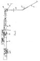
- the sweeping aiding device which has been generally indicated by the reference number 1, comprises a semiautomatic two articulated-joint arm, comprising a first arm segment 2 fixed at the middle region of the street sweeper 3 above the front portion of the tilting casing 4 thereof, through a first articulated joint 11.
- the above mentioned arm is of a self-moving type, i.e. it can be driven in a plane parallel to the ground, and arranged at a level greater than the maximum height of the sweeper.
- the sweeping operation is performed by using pressurized water delivered from the street sweeping machine and, to that end, the sweeping aiding device ends with a sheath 13 supplying and supporting a sweeping lance 5.
- Said sweeping lance is driven by a walking operator 6, and allow to displace dirt and waste materials from the sidewalks 7 and from the bottom of the cars or vehicles 8 parked at the central portion of the street 9, from which said dirt and waste materials are collected by the sweeper, which in the meanwhile washes the street surface.
- the articulated arm as is shown, comprises a second segment 10 coupled to the first segment 2 by a second articulated joint 12.
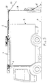
- the two arm segments 2 and 10 in the maximally extended condition thereof, have a length larger than six meters, but a specifically designed system for winding and automatically recovering the sheath 13 allows the operator to move away, if necessary, by other three meters from the sweeper.
- the lance 5 supporting sheath 13 slides, at the end portion of the arm, in a special supporting element 14, of a joystick type, which automatically drives the arm segment, thereby providing an operator tracking length reserve, independently from the movement direction of the operator.
- the walking operator can perform the dirt and waste material removal operation, without considering the position of the sweeper arm.
- the sheath 13 ends with an electric connector and a water quick fitting, allowing, as the sweeping aiding device is in an idle condition above the sweeper, to disconnect the lance 5 for storing it at any other desired location.
- the supporting sheath 13 will be automatically wound within the arm segment 10 and will be bracketed on a side of the casing or box 4.
- the sheath 13 is wound, by a specifically designed winding system, inside the second segment 10 on a cable holder chain 19 coupled to the aiding shoes 20, which can slide at the top in a polyethylene guiding element 21.
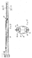
- the sheath 13 projects from the second arm segment 10 through the end portion 18 comprising a control system for controlling the position and movement of said sheath, said control system comprising two potentiometers 23 and 24, each of which is provided with small rollers 25, arranged in respective orthogonal planes, thereby to transmit an electric signal to the control central unit controlling the servomotors 26 and 27 which respectively drive the first and second articulated joints.
- said potentiometers can detect or sense the operator moving speed, so as to properly control the servomotors of the articulated arm to properly track or follow the moving operator.
- a spotlight element having a halogen lamp, mounted on the end portion 18 of the second arm segment 10, will allow the sweeper to also operate in a night period, by diffusely illuminating from the top the working region.
- the two arm segments are compasses-like closed, and are bracketed on the sweeper 3 by an automatic safety locking system.
- the sweeping aiding device will be held inside the sweeper perimeter thereby meeting the maximum height values provided by the Street Code.
- the sweeping aiding device is adapted to indifferently operate on both sides of the sweeper.
- a selector or switch element, arranged on the cab button panel of the sweeper will allow to select the working side and then, the system controlling softer will prevent any further movements on the other side of the sweeper.
- the rotary movements of the two arm segments are motor driven.
- Torque limiting elements together with damping rubber section elements, arranged on the sides of the arms, will protect the equipment from accidental impacts.
- the device bearing construction 15 is coupled, by a removable coupling means, to a fixing or attachment plate 16, rigid with the sweeper casing or box 4.
- said sweeping aiding device anchoring plate 16 is removably coupled, by a coupling bracket, to the front portion of the casing 4 of the sweeper 3.
- the bearing construction can be subjected to the following loads:
- the handle 17 of the lance has integrated therein an on/off joystick electric control to allow the operator to adjust, through a knob control valve, the flow rate of the water being sprayed from the lance 5.
- the device further comprises an independent electric panel, meeting the related CE standards, provided for driving and controlling the sweeper; it comprises: a PLC for controlling the operating and safety logic circuits; I/O cards for managing the transmitted signals; and the electric motor drives.
- the device comprises moreover an independent pushbutton panel, mounted on the sweeper cab, and including the following control pushbuttons: on/off selector; emergency pushbutton; arm extending and withdrawing selector or switch; a selector for operating either at the right or at the left of the truck; a small panel for necessary alarms; an alarm reset pushbutton; and a lighting system on/off selector or switch.
- the driver and walking operator can continuously communicate through a radio-wave interphone system, with an earphone for the walking operator and in a voiced manner for the driver, thereby providing a highly synchronous cooperating of the driver and operator.
- the sweeper can also comprise, onboard, the following provisions, as necessary for operating the sweeping aiding device: electricity 24 V; voltage 24+/-15% Vcc; and useful power 0.85 kW, as necessary for power supplying the arm motors, lighting system and electronic cabinet.
- Pressurized water is advantageously filtered and free of suspensions and has a rated pressure from 60 to 100 bars (adjustable), a maximum pressure of 110 bars and a maximum flowrate of 900 dm 3 /h, for water supplying the water spraying lance.
- the sweeping aiding device can also perform, by small modifications, even a cleaning function, by using an air blower, having a 24 Vcc electric motor, to be coupled to the sheath in place of the sweeping lance, and can also be electrically supplied by the sheath.
- the device can also be applied on a tank truck and can be used for washing streets and sidewalks, since it would have available great amounts of water.
- the device according to the invention can also be applied to a salt delivery truck, thereby delivering salt on the sidewalks and under the parked vehicles, under snow and ice condition.
- the invention provides a sweeping aiding device allowing to sweep and wash streets and sidewalks even in regions occupied by parked vehicles, aiding the operator through the use of a safe, efficient, noiseless and easily manoeuvrable system.
- the used materials, as well as the contingent size and shapes can be any, depending on requirements.
Landscapes
- Engineering & Computer Science (AREA)
- Architecture (AREA)
- Civil Engineering (AREA)
- Structural Engineering (AREA)
- Cleaning In General (AREA)
- Cleaning Of Streets, Tracks, Or Beaches (AREA)
- Machines For Laying And Maintaining Railways (AREA)
- Automatic Cycles, And Cycles In General (AREA)
- Harvester Elements (AREA)
- Brushes (AREA)
Abstract
Description
(in any directions through 360° about the axle)
Claims (27)
- A sweeping aiding device, to be applied to municipal street sweepers, characterized in that said device comprises a servo-controlled articulated arm, which can be coupled to a street sweeper and comprises a windable sheath bearing, at one end portion thereof, a sweeping lance adapted to provide pressurized water and to be gripped by an operator.
- A device, according to claim 1, characterized in that said device comprises a semiautomatic two articulated joint arm, including a first arm segment fixed at the middle of the sweeper, above a front portion of the tilting casing or box thereof, through a first articulated joint.
- A device, according to claim 1 or 2, characterized in that said articulated arm is self-movable in a plane parallel to the ground, arranged at a level greater than the maximum height of the sweeper.
- A device, according to one or more of the preceding claims, characterized in that said articulated arm comprises a second arm segment, coupled to the first arm by a second articulated joint.
- A device, according to one or more of the preceding claims, characterized in that said two arm segments, in a maximum extension condition thereof, have a length greater than six meters, an automatic winding and recovering system being moreover provided for winding the sheath to allow the operator to move away from the sweeper by additional three meters.
- A device, according to one or more of the preceding claims, characterized in that the lance supporting sheath, at an end portion of the arm, slides in a joystick supporting element automatically driving the arm segments, thereby providing a reserve length for allowing the operator to easily follow the sweeper according to any directions.
- A device, according to one or more of the preceding claims, characterized in that said sheath ends with an electric connector and a water quick fitting thereby allowing, with said device in a rest condition on the sweeper, to disconnect said lance and store it at any other desired locations, said supporting sheath being automatically wound in said arm segment and being then bracketed on a sidewall of the sweeper casing.
- A device, according to one or more of the preceding claims, characterized in that said sheath is wound by a winding system inside the second arm segment, on a cable holder chain associated with slidable shoes which can slide on the top in a polyethylene guiding element.
- A device, according to one or more of the preceding claims, characterized in that at the bottom of said second arm segment are provided, inside said segment, having an oval cross-section, electric cable ducts.
- A device, according to one or more of the preceding claims, characterized in that said sheath projects from said second arm segment through the end portion comprising a control system for controlling the position and movement of said sheath, said control system comprising two potentiometers, each including rollers arranged in respective orthogonal planes, to transmit an electric signal to a control central unit controlling the operation of the servomotors respectively driving the first articulated joint and second articulated joint, thereby, as the operator moves according to any direction, he will drive said sheath in an univocally defined direction, which is precisely defined by the rotary movements of said two potentiometers.
- A device, according to one or more of the preceding claims, characterized in that said potentiometers are adapted to detect the operator moving speed, so as to operate the servomotors of the articulated arm to follow the operator movement.
- A device, according to one or more of the preceding claims, characterized in that said device further comprises a spotlight element including a halogen lamp, mounted on the end portion of the second segment, and allowing the sweeper to also be used in night time, said spotlight diffusely illuminating the working region from the top.
- A device, according to one or more of the preceding claims, characterized in that, at a rest or idle position thereof, said two articulated arm segments are compasses-like closed and bracketed on the sweeper by an automatic safety locking system, so that, in this arrangement, the size of said device will be held inside the sweeper perimeter, thereby meeting the maximum height values provided by the Street Code.
- A device, according to one or more of the preceding claims, characterized in that said device is designed for indifferently working on both sides of the sweeper.
- A device, according to one or more of the preceding claims, characterized in that said device further comprises a selector, arranged on a drive cab pushbutton panel, allowing to select the working side, to allow the system controlling software to prevent any movements on the other side of the sweeper.
- A device, according to one or more of the preceding claims, characterized in that said arm segments are automatically rotatively driven, an that said device further comprises torque limiting elements which, together with damping rubber section elements, arranged on the sides of the arms, protect the device from accidental impacts.
- A device, according to one or more of the preceding claims, characterized in that the device bearing structure is removably coupled to an attachment plate rigid with the sweeper casing.
- A device, according to one or more of the preceding claims, characterized in that said plate is removably coupled, through a coupling bracket, to the front portion of the sweeper casing.
- A device, according to one or more of the preceding claims, characterized in that said lance has a lance gripper in which is integrated an on/off joystick electric control allowing the operator to adjust, through a knob controlling valve, the water flowrate from said lance.
- A device, according to one or more of the preceding claims, characterized in that said device further comprises an independent electric panel, meeting the CE's standards, adapted to drive and control the sweeper; said panel comprising a PLC for controlling the operating and safety logic circuits; I/O cards for managing the signals, and the electric motor drives.
- A device, according to one or more of the preceding claims, characterized in that said device further comprises an independent push button panel, arranged in the sweeper drive cab, and including the following controls: on/off selector switch; emergency pushbutton; arm extending and withdrawing selector; a selector for allowing the device to operate either on the right or on the left of the sweeper truck; an alarm panel; an alarm reset pushbutton; a lighting on/off selector.
- A device, according to one or more of the preceding claims, characterized in that said device further comprises, onboard of said sweeper, the following services for operating the sweeping aiding device: electricity 24 V; voltage 24+/-15% Vcc; and useful power 0.85 kW for power supplying the arm motors, the lighting system and electric cabinet.
- A device, according to one or more of the preceding claims, characterized in that pressurized water is filtered and free of suspensions and has a rated pressure from 60 to 100 bars (adjustable), a maximum pressure of 110 bars and a maximum flowrate of 900 dm3/h, for supplying said spraying lance.
- A device, according to one or more of the preceding claims, characterized in that said device is also designed for providing a washing function, by using an air blower, including a 24 Vcc electric motor, to be coupled to said sheath in place of said sweeping lance and which is electrically power supplied by said sheath.
- A device, according to one or more of the preceding claims, characterized in that said device is adapted to be applied on a tank truck and used for washing streets and sidewalks, having available large amounts of water.
- A device, according to one or more of the preceding claims, characterized in that said device is adapted to be applied on a salt spreading truck, to spread salt on sidewalls and under parked vehicles, in snow and ice conditions.
- A device, according to one or more of the preceding claims, characterized in that said device comprises one or more of the disclosed and/or illustrated characteristics.
Applications Claiming Priority (2)
| Application Number | Priority Date | Filing Date | Title |
|---|---|---|---|
| IT001459A ITMI20031459A1 (en) | 2003-07-16 | 2003-07-16 | BRUSHING AGEVOLATORE DEVICE, APPLICABLE IN PARTICULAR TO MOTOR-SHOOTERS USED IN THE URBAN NETTEZZA SERVICES |
| ITMI20031459 | 2003-07-16 |
Publications (3)
| Publication Number | Publication Date |
|---|---|
| EP1500748A2 true EP1500748A2 (en) | 2005-01-26 |
| EP1500748A3 EP1500748A3 (en) | 2005-08-24 |
| EP1500748B1 EP1500748B1 (en) | 2008-02-13 |
Family
ID=33485509
Family Applications (1)
| Application Number | Title | Priority Date | Filing Date |
|---|---|---|---|
| EP03029360A Expired - Lifetime EP1500748B1 (en) | 2003-07-16 | 2003-12-19 | Sweeping aiding device for municipal street cleaning sweepers |
Country Status (5)
| Country | Link |
|---|---|
| EP (1) | EP1500748B1 (en) |
| AT (1) | ATE386168T1 (en) |
| DE (1) | DE60319077T2 (en) |
| ES (1) | ES2301751T3 (en) |
| IT (1) | ITMI20031459A1 (en) |
Cited By (2)
| Publication number | Priority date | Publication date | Assignee | Title |
|---|---|---|---|---|
| ITMI20120079A1 (en) * | 2012-01-25 | 2013-07-26 | Amsa S P A Societa Per Azioni Con Socio Unico | BRUSHING AGEVOLATORE DEVICE WITH FOLLI ARMS, PARTICULARLY FOR MOTOR-SANDWIDERS USED IN THE URBAN NETTEZZA SERVICES. |
| EP4647554A1 (en) | 2024-05-07 | 2025-11-12 | Ingegneri Associati Production S.r.l. | Device for facilitating sweeping for street sweepers or street washers |
Families Citing this family (1)
| Publication number | Priority date | Publication date | Assignee | Title |
|---|---|---|---|---|
| DE102018008269A1 (en) | 2018-04-13 | 2019-10-17 | Hako Gmbh | street sweeper |
Family Cites Families (4)
| Publication number | Priority date | Publication date | Assignee | Title |
|---|---|---|---|---|
| DE2916012A1 (en) * | 1979-04-20 | 1980-10-30 | Porsche Ag | Servo suction road cleaning machine - has air duct with end suction and blower nozzles cleaning under parked vehicles |
| FR2626023B1 (en) * | 1988-01-20 | 1994-05-06 | Euronov | MULTIFUNCTIONAL DEVICE FOR REMOTE CLEANING AND TREATMENT OF SURFACES, ARTICLES AND OBJECTS LOCATED AT THE EDGE OF TRAFFIC LANES |
| DE4417126C2 (en) * | 1994-05-16 | 1998-07-09 | Karl Wiedemann | Sewer cleaning vehicle |
| ITMI20011832A1 (en) * | 2001-08-30 | 2003-03-02 | Amsa S P A Azienda Milanese Se | SWEEPER FACING DEVICE, PARTICULARLY FOR MOTOR SWEEPERS USED IN URBAN NETWORK SERVICES |
-
2003
- 2003-07-16 IT IT001459A patent/ITMI20031459A1/en unknown
- 2003-12-19 DE DE60319077T patent/DE60319077T2/en not_active Expired - Lifetime
- 2003-12-19 EP EP03029360A patent/EP1500748B1/en not_active Expired - Lifetime
- 2003-12-19 AT AT03029360T patent/ATE386168T1/en active
- 2003-12-19 ES ES03029360T patent/ES2301751T3/en not_active Expired - Lifetime
Cited By (2)
| Publication number | Priority date | Publication date | Assignee | Title |
|---|---|---|---|---|
| ITMI20120079A1 (en) * | 2012-01-25 | 2013-07-26 | Amsa S P A Societa Per Azioni Con Socio Unico | BRUSHING AGEVOLATORE DEVICE WITH FOLLI ARMS, PARTICULARLY FOR MOTOR-SANDWIDERS USED IN THE URBAN NETTEZZA SERVICES. |
| EP4647554A1 (en) | 2024-05-07 | 2025-11-12 | Ingegneri Associati Production S.r.l. | Device for facilitating sweeping for street sweepers or street washers |
Also Published As
| Publication number | Publication date |
|---|---|
| DE60319077D1 (en) | 2008-03-27 |
| EP1500748B1 (en) | 2008-02-13 |
| DE60319077T2 (en) | 2009-02-05 |
| EP1500748A3 (en) | 2005-08-24 |
| ATE386168T1 (en) | 2008-03-15 |
| ITMI20031459A1 (en) | 2005-01-17 |
| ES2301751T3 (en) | 2008-07-01 |
Similar Documents
| Publication | Publication Date | Title |
|---|---|---|
| JP7381022B2 (en) | Automatic road sweeper and road cleaning method using the above road sweeper | |
| KR101084309B1 (en) | Roadway Separator Sweepers | |
| US20050102778A1 (en) | Rotary broom attachment for traction vehicles | |
| US20100136890A1 (en) | Riding Apparatus For Treating Floor Surfaces With A Power Cord Handling Swing Arm | |
| EP1500748B1 (en) | Sweeping aiding device for municipal street cleaning sweepers | |
| CN112627092B (en) | Washing vehicle | |
| CA2794892A1 (en) | Snow removing system | |
| CA3015581C (en) | Barn floor cleaner | |
| CN106760627A (en) | A kind of intelligent robot road garbage cleaning car | |
| CN112900333B (en) | Automatic running cleaning machine | |
| US20170056938A1 (en) | Device for clearing an area around elevated objects | |
| KR100766315B1 (en) | Sidewalk Water Cleaning Equipment | |
| US4135270A (en) | Portable carwash apparatus | |
| EP1970270B1 (en) | Mobile cleaning device | |
| KR102099219B1 (en) | Sagway based boarding type cleaner | |
| EP1288374B1 (en) | Sweeping aiding device for sweepers | |
| CN110258421A (en) | A kind of municipal works road ponding processing vehicle | |
| US7578885B2 (en) | Concrete/asphalt wet washing system | |
| CN206299151U (en) | Intelligent robot road garbage cleaning car | |
| KR200243436Y1 (en) | A garbage wagon for guide rail | |
| US10709104B2 (en) | Barn floor cleaner | |
| CN221422481U (en) | Snow-removing and ice-removing operation device | |
| CN222663296U (en) | Cleaning system | |
| CN220767876U (en) | Cleaning device and cleaning vehicle | |
| CN210975677U (en) | Dual-purpose cleaning device for highway pavement and milestone |
Legal Events
| Date | Code | Title | Description |
|---|---|---|---|
| PUAI | Public reference made under article 153(3) epc to a published international application that has entered the european phase |
Free format text: ORIGINAL CODE: 0009012 |
|
| AK | Designated contracting states |
Kind code of ref document: A2 Designated state(s): AT BE BG CH CY CZ DE DK EE ES FI FR GB GR HU IE IT LI LU MC NL PT RO SE SI SK TR |
|
| AX | Request for extension of the european patent |
Extension state: AL LT LV MK |
|
| PUAL | Search report despatched |
Free format text: ORIGINAL CODE: 0009013 |
|
| AK | Designated contracting states |
Kind code of ref document: A3 Designated state(s): AT BE BG CH CY CZ DE DK EE ES FI FR GB GR HU IE IT LI LU MC NL PT RO SE SI SK TR |
|
| AX | Request for extension of the european patent |
Extension state: AL LT LV MK |
|
| 17P | Request for examination filed |
Effective date: 20051014 |
|
| AKX | Designation fees paid |
Designated state(s): AT BE BG CH CY CZ DE DK EE ES FI FR GB GR HU IE IT LI LU MC NL PT RO SE SI SK TR |
|
| 17Q | First examination report despatched |
Effective date: 20060810 |
|
| 17Q | First examination report despatched |
Effective date: 20060810 |
|
| GRAP | Despatch of communication of intention to grant a patent |
Free format text: ORIGINAL CODE: EPIDOSNIGR1 |
|
| GRAS | Grant fee paid |
Free format text: ORIGINAL CODE: EPIDOSNIGR3 |
|
| GRAA | (expected) grant |
Free format text: ORIGINAL CODE: 0009210 |
|
| AK | Designated contracting states |
Kind code of ref document: B1 Designated state(s): AT BE BG CH CY CZ DE DK EE ES FI FR GB GR HU IE IT LI LU MC NL PT RO SE SI SK TR |
|
| REG | Reference to a national code |
Ref country code: GB Ref legal event code: FG4D |
|
| REG | Reference to a national code |
Ref country code: CH Ref legal event code: EP |
|
| REG | Reference to a national code |
Ref country code: IE Ref legal event code: FG4D |
|
| REF | Corresponds to: |
Ref document number: 60319077 Country of ref document: DE Date of ref document: 20080327 Kind code of ref document: P |
|
| REG | Reference to a national code |
Ref country code: CH Ref legal event code: NV Representative=s name: BOVARD AG PATENTANWAELTE |
|
| REG | Reference to a national code |
Ref country code: ES Ref legal event code: FG2A Ref document number: 2301751 Country of ref document: ES Kind code of ref document: T3 |
|
| PG25 | Lapsed in a contracting state [announced via postgrant information from national office to epo] |
Ref country code: FI Free format text: LAPSE BECAUSE OF FAILURE TO SUBMIT A TRANSLATION OF THE DESCRIPTION OR TO PAY THE FEE WITHIN THE PRESCRIBED TIME-LIMIT Effective date: 20080213 |
|
| PG25 | Lapsed in a contracting state [announced via postgrant information from national office to epo] |
Ref country code: SI Free format text: LAPSE BECAUSE OF FAILURE TO SUBMIT A TRANSLATION OF THE DESCRIPTION OR TO PAY THE FEE WITHIN THE PRESCRIBED TIME-LIMIT Effective date: 20080213 |
|
| ET | Fr: translation filed | ||
| PG25 | Lapsed in a contracting state [announced via postgrant information from national office to epo] |
Ref country code: SE Free format text: LAPSE BECAUSE OF FAILURE TO SUBMIT A TRANSLATION OF THE DESCRIPTION OR TO PAY THE FEE WITHIN THE PRESCRIBED TIME-LIMIT Effective date: 20080513 Ref country code: CZ Free format text: LAPSE BECAUSE OF FAILURE TO SUBMIT A TRANSLATION OF THE DESCRIPTION OR TO PAY THE FEE WITHIN THE PRESCRIBED TIME-LIMIT Effective date: 20080213 Ref country code: PT Free format text: LAPSE BECAUSE OF FAILURE TO SUBMIT A TRANSLATION OF THE DESCRIPTION OR TO PAY THE FEE WITHIN THE PRESCRIBED TIME-LIMIT Effective date: 20080714 Ref country code: DK Free format text: LAPSE BECAUSE OF FAILURE TO SUBMIT A TRANSLATION OF THE DESCRIPTION OR TO PAY THE FEE WITHIN THE PRESCRIBED TIME-LIMIT Effective date: 20080213 Ref country code: SK Free format text: LAPSE BECAUSE OF FAILURE TO SUBMIT A TRANSLATION OF THE DESCRIPTION OR TO PAY THE FEE WITHIN THE PRESCRIBED TIME-LIMIT Effective date: 20080213 |
|
| PG25 | Lapsed in a contracting state [announced via postgrant information from national office to epo] |
Ref country code: RO Free format text: LAPSE BECAUSE OF FAILURE TO SUBMIT A TRANSLATION OF THE DESCRIPTION OR TO PAY THE FEE WITHIN THE PRESCRIBED TIME-LIMIT Effective date: 20080213 |
|
| PLBE | No opposition filed within time limit |
Free format text: ORIGINAL CODE: 0009261 |
|
| STAA | Information on the status of an ep patent application or granted ep patent |
Free format text: STATUS: NO OPPOSITION FILED WITHIN TIME LIMIT |
|
| 26N | No opposition filed |
Effective date: 20081114 |
|
| PG25 | Lapsed in a contracting state [announced via postgrant information from national office to epo] |
Ref country code: EE Free format text: LAPSE BECAUSE OF FAILURE TO SUBMIT A TRANSLATION OF THE DESCRIPTION OR TO PAY THE FEE WITHIN THE PRESCRIBED TIME-LIMIT Effective date: 20080213 Ref country code: BG Free format text: LAPSE BECAUSE OF FAILURE TO SUBMIT A TRANSLATION OF THE DESCRIPTION OR TO PAY THE FEE WITHIN THE PRESCRIBED TIME-LIMIT Effective date: 20080513 |
|
| PG25 | Lapsed in a contracting state [announced via postgrant information from national office to epo] |
Ref country code: MC Free format text: LAPSE BECAUSE OF NON-PAYMENT OF DUE FEES Effective date: 20081231 Ref country code: CY Free format text: LAPSE BECAUSE OF FAILURE TO SUBMIT A TRANSLATION OF THE DESCRIPTION OR TO PAY THE FEE WITHIN THE PRESCRIBED TIME-LIMIT Effective date: 20080213 |
|
| PG25 | Lapsed in a contracting state [announced via postgrant information from national office to epo] |
Ref country code: IE Free format text: LAPSE BECAUSE OF NON-PAYMENT OF DUE FEES Effective date: 20081219 |
|
| PG25 | Lapsed in a contracting state [announced via postgrant information from national office to epo] |
Ref country code: LU Free format text: LAPSE BECAUSE OF NON-PAYMENT OF DUE FEES Effective date: 20081219 Ref country code: HU Free format text: LAPSE BECAUSE OF FAILURE TO SUBMIT A TRANSLATION OF THE DESCRIPTION OR TO PAY THE FEE WITHIN THE PRESCRIBED TIME-LIMIT Effective date: 20080814 |
|
| PG25 | Lapsed in a contracting state [announced via postgrant information from national office to epo] |
Ref country code: TR Free format text: LAPSE BECAUSE OF FAILURE TO SUBMIT A TRANSLATION OF THE DESCRIPTION OR TO PAY THE FEE WITHIN THE PRESCRIBED TIME-LIMIT Effective date: 20080213 |
|
| PG25 | Lapsed in a contracting state [announced via postgrant information from national office to epo] |
Ref country code: GR Free format text: LAPSE BECAUSE OF FAILURE TO SUBMIT A TRANSLATION OF THE DESCRIPTION OR TO PAY THE FEE WITHIN THE PRESCRIBED TIME-LIMIT Effective date: 20080514 |
|
| REG | Reference to a national code |
Ref country code: CH Ref legal event code: PFA Owner name: AMSA S.P.A. AZIENDA MILANESE SERVIZI AMBIENTALI Free format text: AMSA S.P.A. AZIENDA MILANESE SERVIZI AMBIENTALI#VIA OLGETTINA, 25#20132 MILANO (IT) -TRANSFER TO- AMSA S.P.A. AZIENDA MILANESE SERVIZI AMBIENTALI#VIA OLGETTINA, 25#20132 MILANO (IT) |
|
| PGFP | Annual fee paid to national office [announced via postgrant information from national office to epo] |
Ref country code: CH Payment date: 20121228 Year of fee payment: 10 |
|
| PGFP | Annual fee paid to national office [announced via postgrant information from national office to epo] |
Ref country code: AT Payment date: 20121219 Year of fee payment: 10 |
|
| PGFP | Annual fee paid to national office [announced via postgrant information from national office to epo] |
Ref country code: BE Payment date: 20121228 Year of fee payment: 10 |
|
| PGFP | Annual fee paid to national office [announced via postgrant information from national office to epo] |
Ref country code: NL Payment date: 20121219 Year of fee payment: 10 |
|
| BERE | Be: lapsed |
Owner name: AMSA S.P.A. AZIENDA MILANESE SERVIZI AMBIENTALI Effective date: 20131231 |
|
| REG | Reference to a national code |
Ref country code: NL Ref legal event code: V1 Effective date: 20140701 |
|
| REG | Reference to a national code |
Ref country code: CH Ref legal event code: PL |
|
| REG | Reference to a national code |
Ref country code: AT Ref legal event code: MM01 Ref document number: 386168 Country of ref document: AT Kind code of ref document: T Effective date: 20131219 |
|
| PG25 | Lapsed in a contracting state [announced via postgrant information from national office to epo] |
Ref country code: LI Free format text: LAPSE BECAUSE OF NON-PAYMENT OF DUE FEES Effective date: 20131231 Ref country code: CH Free format text: LAPSE BECAUSE OF NON-PAYMENT OF DUE FEES Effective date: 20131231 Ref country code: NL Free format text: LAPSE BECAUSE OF NON-PAYMENT OF DUE FEES Effective date: 20140701 Ref country code: BE Free format text: LAPSE BECAUSE OF NON-PAYMENT OF DUE FEES Effective date: 20131231 |
|
| PG25 | Lapsed in a contracting state [announced via postgrant information from national office to epo] |
Ref country code: AT Free format text: LAPSE BECAUSE OF NON-PAYMENT OF DUE FEES Effective date: 20131219 |
|
| REG | Reference to a national code |
Ref country code: FR Ref legal event code: PLFP Year of fee payment: 13 |
|
| REG | Reference to a national code |
Ref country code: FR Ref legal event code: PLFP Year of fee payment: 14 |
|
| REG | Reference to a national code |
Ref country code: FR Ref legal event code: PLFP Year of fee payment: 15 |
|
| PGFP | Annual fee paid to national office [announced via postgrant information from national office to epo] |
Ref country code: GB Payment date: 20221214 Year of fee payment: 20 Ref country code: FR Payment date: 20221214 Year of fee payment: 20 |
|
| PGFP | Annual fee paid to national office [announced via postgrant information from national office to epo] |
Ref country code: ES Payment date: 20230125 Year of fee payment: 20 |
|
| PGFP | Annual fee paid to national office [announced via postgrant information from national office to epo] |
Ref country code: IT Payment date: 20221223 Year of fee payment: 20 Ref country code: DE Payment date: 20230102 Year of fee payment: 20 |
|
| P01 | Opt-out of the competence of the unified patent court (upc) registered |
Effective date: 20230309 |
|
| P02 | Opt-out of the competence of the unified patent court (upc) changed |
Effective date: 20230414 |
|
| REG | Reference to a national code |
Ref country code: DE Ref legal event code: R071 Ref document number: 60319077 Country of ref document: DE |
|
| REG | Reference to a national code |
Ref country code: ES Ref legal event code: FD2A Effective date: 20231227 |
|
| REG | Reference to a national code |
Ref country code: GB Ref legal event code: PE20 Expiry date: 20231218 |
|
| PG25 | Lapsed in a contracting state [announced via postgrant information from national office to epo] |
Ref country code: GB Free format text: LAPSE BECAUSE OF EXPIRATION OF PROTECTION Effective date: 20231218 |
|
| PG25 | Lapsed in a contracting state [announced via postgrant information from national office to epo] |
Ref country code: ES Free format text: LAPSE BECAUSE OF EXPIRATION OF PROTECTION Effective date: 20231220 |
|
| PG25 | Lapsed in a contracting state [announced via postgrant information from national office to epo] |
Ref country code: GB Free format text: LAPSE BECAUSE OF EXPIRATION OF PROTECTION Effective date: 20231218 Ref country code: ES Free format text: LAPSE BECAUSE OF EXPIRATION OF PROTECTION Effective date: 20231220 |