EP1500754A2 - Améliorations d'une ou concernant une plate-forme d'accès - Google Patents
Améliorations d'une ou concernant une plate-forme d'accès Download PDFInfo
- Publication number
- EP1500754A2 EP1500754A2 EP04017655A EP04017655A EP1500754A2 EP 1500754 A2 EP1500754 A2 EP 1500754A2 EP 04017655 A EP04017655 A EP 04017655A EP 04017655 A EP04017655 A EP 04017655A EP 1500754 A2 EP1500754 A2 EP 1500754A2
- Authority
- EP
- European Patent Office
- Prior art keywords
- frame
- platform
- platform according
- posts
- unit
- Prior art date
- Legal status (The legal status is an assumption and is not a legal conclusion. Google has not performed a legal analysis and makes no representation as to the accuracy of the status listed.)
- Withdrawn
Links
Images




Classifications
-
- E—FIXED CONSTRUCTIONS
- E06—DOORS, WINDOWS, SHUTTERS, OR ROLLER BLINDS IN GENERAL; LADDERS
- E06C—LADDERS
- E06C1/00—Ladders in general
- E06C1/02—Ladders in general with rigid longitudinal member or members
- E06C1/38—Special constructions of ladders, e.g. ladders with more or less than two longitudinal members, ladders with movable rungs or other treads, longitudinally-foldable ladders
- E06C1/39—Ladders having platforms; Ladders changeable into platforms
-
- E—FIXED CONSTRUCTIONS
- E04—BUILDING
- E04G—SCAFFOLDING; FORMS; SHUTTERING; BUILDING IMPLEMENTS OR AIDS, OR THEIR USE; HANDLING BUILDING MATERIALS ON THE SITE; REPAIRING, BREAKING-UP OR OTHER WORK ON EXISTING BUILDINGS
- E04G1/00—Scaffolds primarily resting on the ground
- E04G1/28—Scaffolds primarily resting on the ground designed to provide support only at a low height
-
- E—FIXED CONSTRUCTIONS
- E04—BUILDING
- E04G—SCAFFOLDING; FORMS; SHUTTERING; BUILDING IMPLEMENTS OR AIDS, OR THEIR USE; HANDLING BUILDING MATERIALS ON THE SITE; REPAIRING, BREAKING-UP OR OTHER WORK ON EXISTING BUILDINGS
- E04G1/00—Scaffolds primarily resting on the ground
- E04G1/34—Scaffold constructions able to be folded in prismatic or flat parts or able to be turned down
-
- E—FIXED CONSTRUCTIONS
- E04—BUILDING
- E04G—SCAFFOLDING; FORMS; SHUTTERING; BUILDING IMPLEMENTS OR AIDS, OR THEIR USE; HANDLING BUILDING MATERIALS ON THE SITE; REPAIRING, BREAKING-UP OR OTHER WORK ON EXISTING BUILDINGS
- E04G5/00—Component parts or accessories for scaffolds
- E04G5/10—Steps or ladders specially adapted for scaffolds
-
- E—FIXED CONSTRUCTIONS
- E06—DOORS, WINDOWS, SHUTTERS, OR ROLLER BLINDS IN GENERAL; LADDERS
- E06C—LADDERS
- E06C1/00—Ladders in general
- E06C1/02—Ladders in general with rigid longitudinal member or members
- E06C1/38—Special constructions of ladders, e.g. ladders with more or less than two longitudinal members, ladders with movable rungs or other treads, longitudinally-foldable ladders
- E06C1/397—Special constructions of ladders, e.g. ladders with more or less than two longitudinal members, ladders with movable rungs or other treads, longitudinally-foldable ladders characterised by having wheels, rollers, or runners
-
- E—FIXED CONSTRUCTIONS
- E04—BUILDING
- E04G—SCAFFOLDING; FORMS; SHUTTERING; BUILDING IMPLEMENTS OR AIDS, OR THEIR USE; HANDLING BUILDING MATERIALS ON THE SITE; REPAIRING, BREAKING-UP OR OTHER WORK ON EXISTING BUILDINGS
- E04G1/00—Scaffolds primarily resting on the ground
- E04G1/24—Scaffolds primarily resting on the ground comprising essentially special base constructions; comprising essentially special ground-engaging parts, e.g. inclined struts, wheels
- E04G2001/242—Scaffolds movable on wheels or tracks
Definitions
- THE PRESENT INVENTION relates to an access platform, and more particularly relates to an access platform to provide low level access.
- the present invention seeks to provide an improved low level access platform.
- an access platform comprising a support, a pivotable frame pivotally mounted to the support and moveable between a substantially horizontal storage position and a substantially vertical operational position, at least one retaining element being provided to retain the frame in said operational position, a platform unit being provided, the platform unit being configured to engage the frame when the frame is in said operational position so as to adopt an elevated position relative to said support, wherein, the or each said retaining element comprises a hinged strut pivotally connected at one end to the frame and pivotally connected at its other end to the support.
- said frame comprises a pair of substantially parallel stiles and at least one cross-member extending between the stiles.
- said frame is a ladder frame comprising a plurality of said cross-members in the form of rungs.
- the or each said strut is connected to the frame at a point intermediate the ends of the stiles.
- a single said retaining element is provided, the retaining element being pivotally connected to one of the or each said cross-members of the frame.
- the platform unit is provided with posts at its four corners.
- said post are fixed to the platform unit.
- supplementary posts are provided which are engageable with the fixed posts to form a guard on the platform.
- the posts are removable from the platform unit.
- the platform unit is provided with releasable fastening elements configured to engage releasably rungs of the ladder frame to mount the platform unit to the ladder frame in a substantially horizontal position.
- one side edge of the platform unit is provided with a plurality of clamping hooks to engage a selective rung of the ladder frame, and struts are provided connected to the underside of the platform unit which are provided with engagement elements to engage another rung of the ladder frame.
- the struts are pivotally mounted to the underside of the platform and are provided with clamping hooks to engage the said rung of the ladder frame.
- the platform has a second frame in addition to said pivotable frame, the second frame being a ladder frame comprising a pair of substantially parallel stiles and a plurality of rungs, wherein both of said frames are pivotally mounted to said support.
- said platform unit is pivotally connected to both of said frames.
- said frames are configured such that said platform remains substantially horizontal as said frame is moved between its storage position and its operational position.
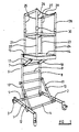
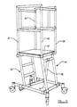
- the access platform of the first embodiment comprises two spaced-apart base rails 1, 2, each end of each base rail being provided with a respective castor 3. Intermediate their ends the base rails are interconnected by a transverse element 4 which is pivotally connected to the base rails 1, 2. Adjacent one end the base rails 1, 2 are interconnected by a further transverse element 5, the further transverse element 5 again being pivotally connected to the base rails 1, 2.
- the further transverse element 5 effectively forms the lower-most rung of a ladder frame 6, the ladder frame 6 having two stiles 7, 8 interconnected by transverse cross members, such as the rung 9.
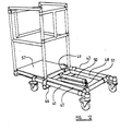
- the ladder frame 6 is pivotally mounted, by virtue of the pivotal mounting of the further transverse member 5 and may be moved, as will become clear from the following description, from the vertical or substantially vertical operational position illustrated in Figure 1 to a horizontal or substantially horizontal storage position as illustrated in Figure 2.
- each hinged strut having a hinge 12, 13 at a centrally located position.
- One end of each hinged strut is connected to the first transverse member 4, and the other end of each hinged strut is pivotally connected to a respective stile 7, 8 of the ladder frame 6 at a point intermediate the ends of the stile.
- the hinged struts are of such a length that they may be locked in a linear position when the ladder frame 6 is vertical.
- the struts may be unlocked and folded about their hinges to permit the ladder frame 6 to move to a horizontal position as shown in Figure 2.
- the hinges may pass over-dead-centre, or may be provided with locking sleeves.
- the hinges may be provided with a sprung locking catch.
- the struts act as retaining elements to retain the frame in the vertical operational position.
- a square platform unit 14 is provided. One edge of the platform unit is provided with two clamping hooks, 15, 16 which can clampingly engage a rung of the ladder frame.
- the platform is provided with two locating struts 17, 18 which are pivotally connected to the under-surface of the platform and which terminate with clamping hooks 19, 20 which again can engage a rung of the ladder frame 6.
- the platform may be mounted in position on the ladder frame with the clamping hooks 15, 16 provided on the platform engaged in the upper-most rung, and the clamping hooks 19, 20 provided on the strut 17, 18 engaging the next adjacent rung. The platform is thus maintained in a horizontal position.
- a fixed upstanding post 21, 22, 23, 24 At each corner of the platform unit there is a fixed upstanding post 21, 22, 23, 24.
- Four supplementary posts 25, 26, 27, 28 are provided which may be mounted in the upper-most ends of the fixed posts.
- the four supplementary posts are provided as two pairs of posts, each pair of posts being interconnected by a cross-piece.
- the ends of the posts which are not interconnected by the cross-piece are each pivotally connected by an appropriate hinge to one end of a fixed upstanding post.
- the two posts, with the cross-piece are thus of "n" form and may hinge from a lower retracted position to an upper extended position.
- the pairs of supplementary posts are interconnected by two chains 29.
- the platform may be mounted at alternate positions on the ladder frame, being positioned somewhat lower than the position illustrated in Figure 1.
- Figures 3 and 4 illustrate by way of example, such alternate positions.
- the platform 14 extends over the area surrounded by the four castors 3 and thus the platform is stable.
- the castors may be provided with brakes to lock the castors firmly in position to prevent the platform from moving inadvertently.
- the entire platform 14 and the associated fixed posts 21-24 is removed from the ladder frame 6.
- the hinged struts 10, 11 are released so that the hinges 12, 13 may be hinged and the ladder frame 6 is then lowered to a horizontal position.
- the supplementary posts 25, 26, 27, 28 are hinged down relative to the fixed posts 21, 22, 23, 24 by the hinges 30.
- the platform may then be re-mounted on appropriate rungs of the ladder frame, using the clamping hooks so that the entire unit is compact and may be easily transported, as illustrated in Figure 8.
- the platform is releasably connected to the ladder frame
- the platform may be securely fixed to the frame which, in this embodiment, need not be a ladder frame.
- a range of platforms may be provided, each with a frame of a different size, but with the platform permanently mounted to the frame.
- the platform may be pivotally mounted to the frame, so as to be able to swing relative to the frame as the frame itself is moved from the vertical or upright position to the lower or horizontal position.
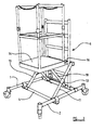
- an access platform of the second embodiment of the present invention again comprises two spaced-apart base rails 41, 42, each end of each base rail being provided with a respective castor 43.
- the base rails 41, 42 are interconnected by a transverse element 44 which is pivotally connected to the base rails 41, 42 so as to extend therebetween at a level below the plane in which the base rails 41, 42 themselves are located.
- Adjacent one end, the base rails 41, 42 are also interconnected by a further transverse element 45 which may again be pivotally connected to the base rails 41, 42 but which in the particular arrangement illustrated in Figure 9 is rigidly connected to the base rails 41, 42.
- a pivotal support frame 46 is connected to and extends upwardly from the transverse element 45.
- the frame 46 comprises a pair of substantially parallel stiles 47, 48 which are interconnected near their upper ends by a transverse cross member 49.
- the lowermost end of each stile 47, 48 is, in the embodiment illustrated in Figure 9, pivotally mounted to the transverse element 45 such that the frame 46 is pivotally mounted to the support defined by the base rails 41, 42 and may be moved, as will become clear from the following description, from the substantially vertical operational position illustrated in Figure 9 to a substantially horizontal storage position illustrated in Figure 12.
- the stiles 47, 48 can simply be rigidly connected to the transverse element 45.
- a hinged strut 50 is provided which has a hinge 51 at a centrally-located position. One end of the hinged strut 50 is connected to the first transverse member 44, and the other end of the hinged strut 50 is pivotally connected to the cross member 40 of the frame 46 at a point between the two stiles 47, 48.
- the hinged strut 50 is of such a length that it may be locked in a linear or substantially linear position when the frame 46 is substantially vertical.
- the strut 50 may be locked and folded about its hinge 51 to permit the frame 6 to move to a horizontal position as shown in Figures 11 and 12.
- the hinge 51 may pass over-dead-centre or may be provided with a locking sleeve.
- the hinge 51 may be provided with a sprung locking patch. It should therefore be apparent that the strut 50 acts as a retaining element to retain the frame 6 in the substantially vertical operational position illustrated in Figure 9.
- a further frame 52 which takes the form of a ladder frame comprising a pair of parallel stiles 53, 54 which are interconnected by a plurality of transverse cross members such as rungs 55, 56.
- the two stiles 53, 54 of the further frame 52 are connected to the first transverse element 44 and hence the leather frame 52 is also pivotally mounted and so can be moved, as will become clear, from the substantially vertical operational position illustrated in Figure 1 to a substantially horizontal storage position as illustrated in Figure 12.
- first frame 46 and the ladder frame 52 are configured so that when they each adopt their respective vertical positions illustrated in Figure 9, the upper ends of the stiles are all spaced above the plane of the base rails 41, 42 by substantially the same distance. Because the first transverse member 44 extends below the base rails 41, 42, whereas the further transverse member 45 extends between the base rails 41, 42, this means that the stiles 53, 54 of the ladder frame 52 are slightly longer than the stiles 47, 48 of the first frame 46.
- a square platform unit 57 is provided which is pivotally connected along one edge to the uppermost ends of the stiles 47, 48 of the first frame 46.
- the platform unit 57 is pivotally connected, along the opposite edge, to the uppermost ends of the stiles 53, 54 of the ladder frame 52.
- each sleeve or socket 58 slidably and releasably receives the lowermost end of a respective upstanding post 59, 60, 61, 62.
- the four upstanding posts 59, 60, 61, 62 are provided as two pairs of posts, each pair of posts being interconnected by an upper cross-piece 63, 64 and a lower cross-piece 65, 66.
- the posts 59, 62, which are not interconnected by the aforementioned cross-pieces are interconnected by a guard frame 67 which comprises a pair of horizontal members and a substantially vertical bracing member therebetween.
- the other two upstanding posts, 60, 61 which are not interconnected by cross-members 63,64,65 or 66 can be selectively interconnected via an openable gate 68 which takes the form of a frame which is pivotally connected to one of the upstanding posts 60 and which is releasably connectable (via an open sleeve or bracket 69) to the other upstanding posts 61.
- the openable gate 68 is provided to selectively interconnect the two upstanding posts which are located on either side of the ladder frame 52. This means that the ladder frame 52 can provide a convenient access ladder to the raised platform 57. A person can simply access the platform 57 by climbing up the ladder frame 52 and then, when the person is standing on the platform 57, the gate 68 can be closed.
- the platform 57 of this embodiment again extends over the area surrounded by the four castors 43 thus ensuring that the complete access platform is stable.
- the castors 43 may be provided with brakes to lock the castors into position to prevent the platform from moving inadvertently.
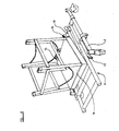
- the hinged strut 50 is initially released so that the hinge 51 may be hinged and the first frame 46 and the ladder frame 52 are then both lowered towards respective substantially horizontal storage positions.
- Figure 11 illustrates the hinge strut 50 being hinged in this manner and it will see that as the frames 46, 52 move towards their substantially horizontal positions, the platform unit 57 remains substantially horizontal.
- FIGURE 12 illustrates the access platform in a position in which the strut 50 has been folded completely in two about its hinge 51. In this position, it will be seen that the stiles 47, 48 of the first support frame 46 lie within the base rails 41, 42 and the cross member 49 lies substantially adjacent the first transverse element 44.
- the platform 57 lies on top of the substantially horizontal ladder frame 52. It will therefore be appreciated that the platform unit 57 has been lowered from its raised position illustrated in Figures 9 and 10 to a position in which it is spaced only a few inches above the ground.
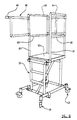
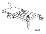
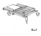
- the two pairs of upstanding posts 59, 60 and 61, 62 can then be lifted upwardly so that their lower ends become disengaged from the respective sleeves or sockets 58. In this way, the two pairs of posts become completely disengaged from the platform unit 57 (as illustrated in Figure 13) and can then simply be placed on top of the folded structure as illustrated in Figure 14 so that all components of the access platform adopt a very low profile configuration which is suitable for storage or easy transport of the arrangement.
- the platform is slidably connected to the frame and is thus permanently attached to the frame, thus minimising the risk of the frame and the platform inadvertently becoming separated.
- the frame may thus be slid between predetermined positions, the frame being held in a predetermined position by means of a securing element such as a bolt or pin which may pass through co-aligned apertures formed in the platform and in the frame.
Landscapes
- Engineering & Computer Science (AREA)
- Architecture (AREA)
- Mechanical Engineering (AREA)
- Civil Engineering (AREA)
- Structural Engineering (AREA)
- Ladders (AREA)
Applications Claiming Priority (4)
| Application Number | Priority Date | Filing Date | Title |
|---|---|---|---|
| GBGB0317398.6A GB0317398D0 (en) | 2003-07-24 | 2003-07-24 | Improvements in or relating to an access platform |
| GB0317398 | 2003-07-24 | ||
| GB0322993A GB2404217A (en) | 2003-07-24 | 2003-10-01 | Foldable access platform |
| GB0322993 | 2003-10-01 |
Publications (2)
| Publication Number | Publication Date |
|---|---|
| EP1500754A2 true EP1500754A2 (fr) | 2005-01-26 |
| EP1500754A3 EP1500754A3 (fr) | 2005-09-07 |
Family
ID=33492265
Family Applications (1)
| Application Number | Title | Priority Date | Filing Date |
|---|---|---|---|
| EP04017655A Withdrawn EP1500754A3 (fr) | 2003-07-24 | 2004-07-26 | Améliorations d'une ou concernant une plate-forme d'accès |
Country Status (1)
| Country | Link |
|---|---|
| EP (1) | EP1500754A3 (fr) |
Cited By (6)
| Publication number | Priority date | Publication date | Assignee | Title |
|---|---|---|---|---|
| GB2443487A (en) * | 2006-11-03 | 2008-05-07 | Birchwood Products Ltd | Collapsible work stand |
| AU2007200652B2 (en) * | 2006-02-22 | 2013-01-17 | Custom Ladder Company Pty Ltd | Safety barrier |
| US20160138338A1 (en) * | 2014-11-19 | 2016-05-19 | Garlock Safety Systems Inc. | Bi-Level Work Platform for ISO Tanks |
| US20160319600A1 (en) * | 2015-04-30 | 2016-11-03 | Romp Enterprise Co., Ltd. | Foldable picking ladder cart |
| JP2018080512A (ja) * | 2016-11-17 | 2018-05-24 | 株式会社大林組 | 作業設備 |
| CN109057692A (zh) * | 2018-08-22 | 2018-12-21 | 国网山东省电力公司安丘市供电公司 | 电力专用绝缘快装检修架 |
Family Cites Families (5)
| Publication number | Priority date | Publication date | Assignee | Title |
|---|---|---|---|---|
| US2354906A (en) * | 1942-10-06 | 1944-08-01 | Russell L Bailey | Airplane scaffold |
| US3007540A (en) * | 1959-10-16 | 1961-11-07 | John P Reinhardt | Personnel work structure convertible to extension ladder and scaffolding means |
| US3463265A (en) * | 1968-07-08 | 1969-08-26 | Fairfield Ind Inc | Telescoping collapsible platform support |
| SU1399427A1 (ru) * | 1986-07-07 | 1988-05-30 | Предприятие П/Я А-7731 | Складна вышка |
| DE8804545U1 (de) * | 1988-04-06 | 1988-09-15 | Leichtmetallbau Mauderer GmbH, 8998 Lindenberg | Konsolgerüst auf Anlegeleitern |
-
2004
- 2004-07-26 EP EP04017655A patent/EP1500754A3/fr not_active Withdrawn
Cited By (8)
| Publication number | Priority date | Publication date | Assignee | Title |
|---|---|---|---|---|
| AU2007200652B2 (en) * | 2006-02-22 | 2013-01-17 | Custom Ladder Company Pty Ltd | Safety barrier |
| GB2443487A (en) * | 2006-11-03 | 2008-05-07 | Birchwood Products Ltd | Collapsible work stand |
| US20160138338A1 (en) * | 2014-11-19 | 2016-05-19 | Garlock Safety Systems Inc. | Bi-Level Work Platform for ISO Tanks |
| US20160319600A1 (en) * | 2015-04-30 | 2016-11-03 | Romp Enterprise Co., Ltd. | Foldable picking ladder cart |
| US9834987B2 (en) * | 2015-04-30 | 2017-12-05 | Romp Enterprise Co., Ltd. | Foldable picking ladder cart |
| JP2018080512A (ja) * | 2016-11-17 | 2018-05-24 | 株式会社大林組 | 作業設備 |
| CN109057692A (zh) * | 2018-08-22 | 2018-12-21 | 国网山东省电力公司安丘市供电公司 | 电力专用绝缘快装检修架 |
| CN109057692B (zh) * | 2018-08-22 | 2019-11-01 | 国网山东省电力公司安丘市供电公司 | 电力专用绝缘快装检修架 |
Also Published As
| Publication number | Publication date |
|---|---|
| EP1500754A3 (fr) | 2005-09-07 |
Similar Documents
| Publication | Publication Date | Title |
|---|---|---|
| CA2932305C (fr) | Escabeau adapte pour etre utilise comme echelle ou comme rallonge d'echelle | |
| US20170328131A1 (en) | Hybrid Stepladder and Method | |
| US5481988A (en) | Telescoping work platform | |
| WO2016131839A1 (fr) | Plates-formes surélevées pliables | |
| EP1392940B1 (fr) | Echafaudage repliable | |
| CA2594804A1 (fr) | Echelle transformable pliante | |
| US5685391A (en) | Triladder | |
| CA3135153A1 (fr) | Echaffaudage de travail et methode | |
| US7255198B1 (en) | Tripod extension stepladder | |
| AU2002311439A1 (en) | Collapsible scaffolding tower | |
| EP1500754A2 (fr) | Améliorations d'une ou concernant une plate-forme d'accès | |
| GB2419373A (en) | Foldable access platform | |
| GB2404217A (en) | Foldable access platform | |
| JP2007532809A (ja) | 屋根裏梯子アッセンブリー | |
| GB2431427A (en) | Scaffolding guard rail | |
| GB2538349A (en) | Mobile scaffolding | |
| EP0598049A1 (fr) | Estrade repliable a plusieurs niveaux | |
| GB2211237A (en) | Support platform | |
| CA1263881A (fr) | Plate-forme de travail adaptable pour mecanicien sur vehicule | |
| US20080164097A1 (en) | Collapsible Combination Ladder | |
| GB2443487A (en) | Collapsible work stand | |
| CN220769345U (zh) | 可伸缩及折叠护栏梯 | |
| KR100905091B1 (ko) | 접철식 발판 | |
| WO2001012920A1 (fr) | Plate-forme d'acces | |
| HK1113184A (en) | Collapsible combination ladder |
Legal Events
| Date | Code | Title | Description |
|---|---|---|---|
| PUAI | Public reference made under article 153(3) epc to a published international application that has entered the european phase |
Free format text: ORIGINAL CODE: 0009012 |
|
| AK | Designated contracting states |
Kind code of ref document: A2 Designated state(s): AT BE BG CH CY CZ DE DK EE ES FI FR GB GR HU IE IT LI LU MC NL PL PT RO SE SI SK TR |
|
| AX | Request for extension of the european patent |
Extension state: AL HR LT LV MK |
|
| PUAL | Search report despatched |
Free format text: ORIGINAL CODE: 0009013 |
|
| AK | Designated contracting states |
Kind code of ref document: A3 Designated state(s): AT BE BG CH CY CZ DE DK EE ES FI FR GB GR HU IE IT LI LU MC NL PL PT RO SE SI SK TR |
|
| AX | Request for extension of the european patent |
Extension state: AL HR LT LV MK |
|
| AKX | Designation fees paid |
Designated state(s): AT BE BG CH CY CZ DE DK EE ES FI FR GB GR HU IE IT LI LU MC NL PL PT RO SE SI SK TR |
|
| STAA | Information on the status of an ep patent application or granted ep patent |
Free format text: STATUS: THE APPLICATION IS DEEMED TO BE WITHDRAWN |
|
| 18D | Application deemed to be withdrawn |
Effective date: 20060308 |