EP1500917A2 - Procédé et dispositif d'essai de pneus - Google Patents
Procédé et dispositif d'essai de pneus Download PDFInfo
- Publication number
- EP1500917A2 EP1500917A2 EP04008466A EP04008466A EP1500917A2 EP 1500917 A2 EP1500917 A2 EP 1500917A2 EP 04008466 A EP04008466 A EP 04008466A EP 04008466 A EP04008466 A EP 04008466A EP 1500917 A2 EP1500917 A2 EP 1500917A2
- Authority
- EP
- European Patent Office
- Prior art keywords
- tire
- sensor
- geometric data
- measuring
- testing
- Prior art date
- Legal status (The legal status is an assumption and is not a legal conclusion. Google has not performed a legal analysis and makes no representation as to the accuracy of the status listed.)
- Granted
Links
Images


Classifications
-
- G—PHYSICS
- G01—MEASURING; TESTING
- G01M—TESTING STATIC OR DYNAMIC BALANCE OF MACHINES OR STRUCTURES; TESTING OF STRUCTURES OR APPARATUS, NOT OTHERWISE PROVIDED FOR
- G01M17/00—Testing of vehicles
- G01M17/007—Wheeled or endless-tracked vehicles
- G01M17/02—Tyres
- G01M17/027—Tyres using light, e.g. infrared, ultraviolet or holographic techniques
Definitions
- the invention relates to a method for testing tires and a device for Implementation of such a method.
- Testers for tires are already known. This can be the surface of the tire be examined for defects. This can be done in particular by the irradiation with coherent light, in particular laser light.
- the object of the invention is to provide a method and a device of the type specified Kind of improving.
- the method for testing tires is using a test system, the test system having a memory in which Geometry data of the tire are stored, and at least one measuring head for Examination of the surface of the tire includes.
- the measuring head can be a sensor include.
- the or the measuring heads are taking into account the geometry data the tire is positioned to test the surface of the tire. If the Geometry data of the tire are known, ie in the memory of the test system It is possible to use the measuring head (s) used to test the surface of the tire serve to automatically position. This allows the process be automated to test tires.
- the geometric data of the tire may be the outer diameter of the tire and / or the inner diameter of the tire and / or the width of the tire.
- the geometric data of the tire includes the outer diameter and the inner diameter and the width of the tire.
- the geometric data of the tire may be the inside diameter the tread of the tire and / or the mouth width of the tire and / or the contour of the sidewall of the tire.
- the geometry data of the tire can be entered into the memory, which especially manually. Instead or in addition, the Geometry data of the tire are read into the memory, for example from a database, which can happen especially over the Internet.
- the geometry data of the tire instead or additionally be measured.
- the geometric data of the tire becomes automatic or measured automatically.
- the geometry data of the tire can be measured by a sensor.
- a sensor In particular, it is an outgoing sensor.
- triangulation sensors laser triangulation sensors or ultrasound sensors, but also other sensors or sensors giving away.
- a further advantageous development is characterized in that the sensor is moved or moved relative to the tire.
- a horizontal profile of the tire is measured.
- a vertical profile of the tire can also be measured.
- the surface of the tire is preferably tested interferometrically. Therefor An interferometric measuring head can be used.
- the surface of the tire may be formed by projecting structured light being checked.
- the surface of the tire can also be checked by photogrammetry.
- the surface of the tire is checked by the same sensor is measured by the geometry data of the tire or before have been measured.
- the method can then be carried out particularly advantageously be, in particular by the fact that the same sensor first one or measures several or all geometric data of the tire and then the surface of the tire checks.
- the object underlying the invention is in a device for testing of tires, in particular for carrying out the method according to the invention, achieved in that the device comprises a test system which a memory for storing geometric data of the tire and at least one measuring head for testing the surface of the tire.
- the measuring head can a Sensor for testing the surface of the tire may be present.
- the device comprises a measuring device for measuring the geometry data of the tire.
- the measuring device may include a sensor.
- the measuring device and / or the sensor relative to the tire is movable.
- the measuring device or the sensor is so relative movable to a tire that a horizontal profile of the tire and / or a vertical Profile of the tire are measurable or determinable.
- the test system may include an interferometric probe.
- the senor of the measuring head is the same sensor as the sensor of Measuring device.
- the device includes for testing tires a sensor for measuring the geometry data of the tire and preferably subsequent testing of the surface of the tire is used.
- test objects namely Tires
- the method for testing tires by means of a Test system performed which a memory (not shown in the drawing), are stored in the geometry data of the tire 7, and a measuring head 8 for testing the surface of the tire 7 includes.
- the measuring head 8 is taken into consideration the geometric data of the tire 7 for testing the surface of the Tire 7 positioned.
- the geometric data of the tire 7 can be seen from FIG. In the memory are the Outer diameter 1 of the tire, the inner diameter 2 of the tire and the Width 3 of the tire 3 stored. As a result, a model B of the tire 7 can be created which, however, is inadequate in most applications.
- the measuring head 8 comprises a camera C with an optical axis 9 and a Image angle 10.
- the actual field of view of the camera C that is the area of the camera Surface of the tire 7, which at a certain position and orientation of the Camera C in the examination of the surface of the tire 7 can be detected (field of view a single measurement).
- To get out of the position and the angle of view of the camera C is the actual field of view of a single measurement and the number of required ones Measuring positions of the camera used to check the entire surface of the tire required to be able to determine is in many applications
- the knowledge of the inner diameter 4 of the tread of the tire required. The knowledge of the inner diameter 4 of the tread of the tire allows the determination of the object distance, ie the distance of the surface to be tested of the tire to the camera C.
- the jaw width 5 of the tire is of considerable importance, because they the accessibility of the inside to be tested surface or tread of the tire significantly influenced.
- the contour is 6 of the side wall of the tire 7 of considerable importance, in particular for the collision, so to a collision of the measuring head C with the tire 7 to prevent, and the measuring field determination (field of view) in the test the sidewall of the tire 7.
- the mentioned geometry data so the outer diameter 1, the inner diameter 2, the tire width 3, the tread inside diameter 4, the jaw width 5 and / or the sidewall contour 6, can be manually entered and / or read in particular from a database and / or with the help of a barcode.
- this is only possible if the geometry data of the tire is complete are known, but this is not guaranteed in every case.
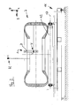
- Fig. 2 shows a device for testing tires with a tire to be tested 7 in a cross section.
- the device comprises a base 11 with a plurality of rollers 12 which are rotatable about horizontal axes 13 extending in the y-direction are stored, so that the flat tire lying on it 7 in the horizontal x-direction is mobile.
- the device comprises a vertically oriented triangulation sensor H and a horizontally oriented triangulation sensor V. While the tire 7 is moved in the horizontal x-direction, the vertical takes oriented triangulation sensor H has a horizontal profile. A second, vertical Profile is obtained by using the horizontally oriented triangulation sensor V moved by a positioning device A in the vertical direction z becomes.
- the triangulation sensor H can additionally be moved in the horizontal y-direction be (not shown in the drawing).
- the measuring direction of the triangulation sensor H runs in the vertical direction opposite to the z-direction.
- the measuring direction of the triangulation sensor V runs in the horizontal direction opposite to y-direction.
- the triangulation sensors H and V allow all geometry data 1 - 6 are measured.
- the device can be designed in such a way that these measurements are automatic.
- Fig. 2 shows a laser triangulation system.
- the geometry data 1 - 6 also by ultrasonic sensors or other weg sacrificede Sensors, with the help of any existing positioning of the device are moved relative to the tire 7 are measured.
- the surface of the tire 7 can by an interferometric tester being checked.
- the test device can be equipped with any additional hardware required be extended as well as evaluation algorithms for coordinate determination with the same or additional cameras.
- a way to test the surface of the tire 7 is in projecting structured light this surface. By projecting, for example, one or more stripes on the surface of the tire by means of a projection device (e.g. Laser diode with line optics, etc.), whose optical axis to the observation direction assuming a known angle, a pattern can be generated in the image, which are evaluated for distance determination via triangulation calculation can.
- a projection device e.g. Laser diode with line optics, etc.
- Fig. 3 the principle of operation of a light section sensor is shown. Through a Projector 14 is thrown structured light on the projection plane 15, in the the tire 7 is located. The reflected light from there is from a camera 16 recorded and displayed on a monitor 17. There is the curved one See profile 18 of the Tire 7.
- any recognizable pattern e.g. Grids, circles, discs, possibly in different colors and / or intensities
- the evaluation software for lines is the easiest.
- the measuring setup shown in FIG. 3 can be used both for testing the surface of the Tire as well as for the measurement of the geometric data of the tire.
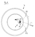
- Fig. 4 shows a tire to be tested 7 in a view from above.
- a laser diode 19 with line optics will be one or more lines 20 on the surface of the tire 7 projected with the shearing camera 21 at a viewing angle 22 to be watched.
- a partial beam be hidden. But this is not absolutely necessary.
- the illumination by the laser diode 19 and the observation by the shearing camera 21 include an angle that allows triangulation through the To determine line coordinates.
- FIG. 5 on the left side, the measuring head positions for measuring the Tire 7 shown.
- the positions to the interferometric Testing the surface of the tire 7 shown where not the overview important, but the high detail resolution.
- the positions according to FIG. 5a and 5b thus serve to measure the geometric data of the tire, the positions in Fig. 5c, d, e and f are for testing the surface of the tire.
- the invention provides a fully automatic tester for tires.
Landscapes
- Physics & Mathematics (AREA)
- General Physics & Mathematics (AREA)
- Length Measuring Devices By Optical Means (AREA)
- Tires In General (AREA)
- Testing Of Balance (AREA)
Applications Claiming Priority (2)
| Application Number | Priority Date | Filing Date | Title |
|---|---|---|---|
| DE10333802A DE10333802B4 (de) | 2003-07-24 | 2003-07-24 | Verfahren und Vorrichtung zum Prüfen von Reifen |
| DE10333802 | 2003-07-24 |
Publications (3)
| Publication Number | Publication Date |
|---|---|
| EP1500917A2 true EP1500917A2 (fr) | 2005-01-26 |
| EP1500917A3 EP1500917A3 (fr) | 2006-05-10 |
| EP1500917B1 EP1500917B1 (fr) | 2010-02-24 |
Family
ID=33483054
Family Applications (1)
| Application Number | Title | Priority Date | Filing Date |
|---|---|---|---|
| EP04008466A Expired - Lifetime EP1500917B1 (fr) | 2003-07-24 | 2004-04-07 | Procédé et dispositif d'essai de pneus |
Country Status (3)
| Country | Link |
|---|---|
| US (1) | US7360410B2 (fr) |
| EP (1) | EP1500917B1 (fr) |
| DE (2) | DE10333802B4 (fr) |
Cited By (8)
| Publication number | Priority date | Publication date | Assignee | Title |
|---|---|---|---|---|
| WO2007110412A1 (fr) * | 2006-03-27 | 2007-10-04 | Maehner Bernward | Dispositif et procédé de contrôle d'un pneu |
| WO2007110414A1 (fr) * | 2006-03-27 | 2007-10-04 | Maehner Bernward | Dispositif et procédé pour vérifier un pneumatique, notamment au moyen d'un procédé de mesure interférométrie |
| WO2007113231A1 (fr) * | 2006-03-31 | 2007-10-11 | Maehner Bernhard | Dispositif et procédé de contrôle d'un pneumatique, en particulier au moyen d'une mesure interférométrique |
| EP2026056A2 (fr) | 2007-08-13 | 2009-02-18 | Steinbichler Optotechnik Gmbh | Dispositif d'essai de pneu |
| EP2105701A1 (fr) * | 2008-03-25 | 2009-09-30 | Steinbichler Optotechnik Gmbh | Procédé et dispositif destinés à la détermination des coordonnées 3D d'un objet |
| CN101245987B (zh) * | 2007-02-16 | 2011-03-23 | 伯尼沃德·梅尼尔 | 尤其借助干涉测量法检测轮胎的装置和方法 |
| FR2981450A1 (fr) * | 2011-10-17 | 2013-04-19 | Eads Europ Aeronautic Defence | Systeme et procede de controle de la qualite d'un objet |
| EP2141476A3 (fr) * | 2008-07-03 | 2014-06-25 | Hankook Tire Co., Ltd | Système et procédé d'analyse de l'uniformité de pneu |
Families Citing this family (20)
| Publication number | Priority date | Publication date | Assignee | Title |
|---|---|---|---|---|
| WO1999034339A2 (fr) | 1997-12-29 | 1999-07-08 | Ameritech Corporation | Systeme de domotique et de telesecurite residentielle et procede associe |
| US8111904B2 (en) | 2005-10-07 | 2012-02-07 | Cognex Technology And Investment Corp. | Methods and apparatus for practical 3D vision system |
| DE102006061003B4 (de) | 2006-12-22 | 2009-03-26 | Mähner, Bernward | Vorrichtung zum Prüfen eines Prüfobjekts, insbesondere eines Reifens, mittels eines zerstörungsfreien Messverfahrens |
| US8126260B2 (en) * | 2007-05-29 | 2012-02-28 | Cognex Corporation | System and method for locating a three-dimensional object using machine vision |
| US9734419B1 (en) | 2008-12-30 | 2017-08-15 | Cognex Corporation | System and method for validating camera calibration in a vision system |
| ES2389916T3 (es) * | 2009-01-22 | 2012-11-05 | Snap-On Equipment Srl A Unico Socio | Sistema de diagnóstico de rueda |
| JP5318657B2 (ja) * | 2009-05-13 | 2013-10-16 | 株式会社ブリヂストン | タイヤの検査装置 |
| US9533418B2 (en) | 2009-05-29 | 2017-01-03 | Cognex Corporation | Methods and apparatus for practical 3D vision system |
| EP2353890A1 (fr) * | 2010-01-29 | 2011-08-10 | Snap-on Equipment Srl a unico socio | Procédé et appareil pour déterminer les dimensions géométriques d'une roue de véhicule avec des capteurs optiques |
| FR2957417B1 (fr) | 2010-03-15 | 2013-01-04 | Michelin Soc Tech | Dispositif de maintien destine a l'inspection visuelle d'un pneumatique |
| US9393694B2 (en) | 2010-05-14 | 2016-07-19 | Cognex Corporation | System and method for robust calibration between a machine vision system and a robot |
| US9124873B2 (en) | 2010-12-08 | 2015-09-01 | Cognex Corporation | System and method for finding correspondence between cameras in a three-dimensional vision system |
| DE102013010402A1 (de) * | 2013-06-21 | 2014-12-24 | Steinbichler Optotechnik Gmbh | Reifenprüfgerät, Reifenprüfanlage und Verfahren zur Reifenprüfung |
| CN106353341A (zh) * | 2016-10-22 | 2017-01-25 | 钟贵洪 | 一种轮胎探测仪 |
| JP6740093B2 (ja) * | 2016-11-11 | 2020-08-12 | Toyo Tire株式会社 | タイヤの検査装置及び検査方法 |
| DE102018001255A1 (de) | 2018-02-18 | 2019-08-22 | Bernward Mähner | Verfahren und Vorrichtung zur Untersuchung von rotationssymmetrischen Prüfobjekten |
| EP4416459B1 (fr) | 2021-10-12 | 2024-12-04 | Dengler, Stefan | Procédé de test de pneumatiques |
| DE102022126613A1 (de) | 2022-10-12 | 2024-04-18 | Stefan Dengler | Verfahren zum Prüfen von Reifen |
| WO2025024919A1 (fr) * | 2023-07-28 | 2025-02-06 | 3Dm Devices Inc. | Appareil d'analyse de pneu et ses procédés d'utilisation |
| WO2025188731A1 (fr) * | 2024-03-04 | 2025-09-12 | Compagnie Generale Des Etablissements Michelin | Inspection améliorée de shéarographie de pneu |
Citations (1)
| Publication number | Priority date | Publication date | Assignee | Title |
|---|---|---|---|---|
| EP1284409A1 (fr) | 2001-08-16 | 2003-02-19 | Bernward Mähner | Procédé et appareil pour l'inspection de la déformation d'objets |
Family Cites Families (17)
| Publication number | Priority date | Publication date | Assignee | Title |
|---|---|---|---|---|
| US3918816A (en) * | 1974-04-22 | 1975-11-11 | Autech Corp | Tire inspection apparatus |
| US4311044A (en) * | 1980-02-25 | 1982-01-19 | The B. F. Goodrich Company | Tire sidewall bump/depression detection system |
| US4526030A (en) * | 1983-05-18 | 1985-07-02 | Vecera Jr Guy L | Multi-functional tire testing tool |
| US4631831A (en) * | 1986-01-31 | 1986-12-30 | Bandag Licensing Corporation | Tread depth probe and computer |
| US5249460A (en) * | 1991-12-16 | 1993-10-05 | Bridgestone Corporation | Method and apparatus for measuring irregular tread wear |
| US5245867A (en) * | 1991-12-16 | 1993-09-21 | Bridgestone Corporation | Method and apparatus for measuring tire parameters |
| DE4232201A1 (de) * | 1992-09-25 | 1994-03-31 | Sp Reifenwerke Gmbh | Vorrichtung zur Querschnittsvermessung von Fahrzeugreifen |
| IT1273333B (it) | 1994-02-24 | 1997-07-08 | Pirelli | Metodo ed apparecchiatura per la tracciatura di un disegno d'impronta sulla fascia battistrada di un pneumatico |
| US6034676A (en) * | 1995-04-11 | 2000-03-07 | Data View, Inc. | System and method for measuring and processing tire depth data |
| JPH09251011A (ja) * | 1996-03-14 | 1997-09-22 | Kawasaki Steel Corp | 回転タイヤ型超音波探触子 |
| US5789668A (en) * | 1996-08-15 | 1998-08-04 | Bridgestone/Firestone, Inc. | Apparatus and related methods for obtaining tire profiles including the tread and both sidewalls |
| ATE221991T1 (de) * | 1997-06-10 | 2002-08-15 | Beissbarth Gmbh | Reifenprüfverfahren und -vorrichtung |
| DE19911913A1 (de) | 1999-03-17 | 2000-09-21 | Beissbarth Gmbh | Reifenprüfverfahren und -Vorrichtung |
| EP1043578B1 (fr) * | 1999-04-09 | 2004-10-13 | Steinbichler Optotechnik Gmbh | Appareil optique pour tester des roues |
| EP1099947A3 (fr) * | 1999-11-12 | 2003-01-29 | Laser Technology Inc. | Procédé et dispositif pour faire un essai optique d'un pneu |
| DE10036010A1 (de) * | 2000-07-25 | 2002-02-07 | Thyssenkrupp Ag | Verfahren zur Kontrolle der Verbindungsstellen |
| DE10319099B4 (de) * | 2003-04-28 | 2005-09-08 | Steinbichler Optotechnik Gmbh | Verfahren zur Interferenzmessung eines Objektes, insbesondere eines Reifens |
-
2003
- 2003-07-24 DE DE10333802A patent/DE10333802B4/de not_active Revoked
-
2004
- 2004-04-07 DE DE502004010797T patent/DE502004010797D1/de not_active Expired - Lifetime
- 2004-04-07 EP EP04008466A patent/EP1500917B1/fr not_active Expired - Lifetime
- 2004-07-26 US US10/899,415 patent/US7360410B2/en not_active Expired - Lifetime
Patent Citations (1)
| Publication number | Priority date | Publication date | Assignee | Title |
|---|---|---|---|---|
| EP1284409A1 (fr) | 2001-08-16 | 2003-02-19 | Bernward Mähner | Procédé et appareil pour l'inspection de la déformation d'objets |
Non-Patent Citations (1)
| Title |
|---|
| "Intact 1200 from Steinbichler", RETREADING BUSINESS, no. 13, February 2000 (2000-02-01), pages 16, XP003011471 |
Cited By (13)
| Publication number | Priority date | Publication date | Assignee | Title |
|---|---|---|---|---|
| WO2007110412A1 (fr) * | 2006-03-27 | 2007-10-04 | Maehner Bernward | Dispositif et procédé de contrôle d'un pneu |
| WO2007110414A1 (fr) * | 2006-03-27 | 2007-10-04 | Maehner Bernward | Dispositif et procédé pour vérifier un pneumatique, notamment au moyen d'un procédé de mesure interférométrie |
| US8074506B2 (en) | 2006-03-27 | 2011-12-13 | Bernward Maehner | Apparatus and method for testing a tire |
| WO2007113231A1 (fr) * | 2006-03-31 | 2007-10-11 | Maehner Bernhard | Dispositif et procédé de contrôle d'un pneumatique, en particulier au moyen d'une mesure interférométrique |
| CN101245987B (zh) * | 2007-02-16 | 2011-03-23 | 伯尼沃德·梅尼尔 | 尤其借助干涉测量法检测轮胎的装置和方法 |
| US7810388B2 (en) | 2007-08-13 | 2010-10-12 | Steinbichler Optotechnik Gmbh | Tire testing facility |
| DE102007038176A1 (de) * | 2007-08-13 | 2009-02-19 | Steinbichler Optotechnik Gmbh | Reifenprüfanlage |
| EP2026056A2 (fr) | 2007-08-13 | 2009-02-18 | Steinbichler Optotechnik Gmbh | Dispositif d'essai de pneu |
| EP2549258A1 (fr) | 2007-08-13 | 2013-01-23 | Steinbichler Optotechnik GmbH | Dispositif d'essai de pneu |
| EP2105701A1 (fr) * | 2008-03-25 | 2009-09-30 | Steinbichler Optotechnik Gmbh | Procédé et dispositif destinés à la détermination des coordonnées 3D d'un objet |
| EP2141476A3 (fr) * | 2008-07-03 | 2014-06-25 | Hankook Tire Co., Ltd | Système et procédé d'analyse de l'uniformité de pneu |
| FR2981450A1 (fr) * | 2011-10-17 | 2013-04-19 | Eads Europ Aeronautic Defence | Systeme et procede de controle de la qualite d'un objet |
| WO2013057115A1 (fr) * | 2011-10-17 | 2013-04-25 | European Aeronautic Defence And Space Company Eads France | Système et procédé de contrôle de la qualité d'un objet |
Also Published As
| Publication number | Publication date |
|---|---|
| DE10333802A1 (de) | 2005-02-24 |
| DE10333802B4 (de) | 2005-09-08 |
| EP1500917B1 (fr) | 2010-02-24 |
| DE502004010797D1 (de) | 2010-04-08 |
| EP1500917A3 (fr) | 2006-05-10 |
| US20050109091A1 (en) | 2005-05-26 |
| US7360410B2 (en) | 2008-04-22 |
Similar Documents
| Publication | Publication Date | Title |
|---|---|---|
| EP1500917B1 (fr) | Procédé et dispositif d'essai de pneus | |
| DE102007009040C5 (de) | Vorrichtung und Verfahren zum Prüfen eines Reifens, insbesondere mittels eines interferometrischen Messverfahrens | |
| EP2732236B1 (fr) | Dispositif et procédé optiques de contrôle de pneumatiques | |
| DE69330466T2 (de) | Verfahren und vorrichtung zur bestimmung der ausrichtung von kraftfahrzeugrädern | |
| DE69828673T2 (de) | Beurteilungsvorrichtung für die Reifenkonfiguration und Reifenklassierungsverfahren | |
| DE4231578C2 (de) | Verfahren zur Ermittlung von Verformungen an einem Prüfobjekt mit diffus streuender Oberfläche, insbesondere an Reifen, sowie Vorrichtung zur Durchführung des Verfahrens | |
| EP2002235B1 (fr) | Dispositif et procede de controle d'un pneumatique, en particulier au moyen d'une mesure interferometrique | |
| EP2574876B1 (fr) | Procédé et dispositif destinés à déterminer les coordonnées 3D d'un objet | |
| EP0995108A1 (fr) | Procede de detection automatique de defauts superficiels au niveau de carrosseries brutes et dispositif permettant de mettre ledit procede en oeuvre | |
| EP2263062B1 (fr) | Dispositif et procédé de mesure topographique de surfaces d'objets | |
| DE102017001750A1 (de) | Innenwandmessinstrument und Versatzbetragsberechnungsverfahren | |
| WO2007080014A1 (fr) | Procédé de mesure optique de châssis | |
| EP1837623B1 (fr) | Procédé et dispositif pour enregistrer la forme d'une surface partiellement réfléchissante | |
| EP2064518B1 (fr) | Procédé pour la détermination des distances en vue de la mesure du train de roulement d'un véhicule automobile | |
| DE112015002961T5 (de) | Verfahren zur Herstellung einer Komponente und Herstellungsvorrichtung, die ein solches Verfahren verwendet, und Volumenmessverfahren | |
| DE10127304A1 (de) | Verfahren und Vorrichtung zur Bestimmung der dreidimensionalen Kontur einer spiegelnden Oberfläche eines Objektes | |
| EP3545259B1 (fr) | Procédé et dispositif d'analyse d'objets de test à symétrie de révolution | |
| DE102004033526A1 (de) | Verfahren und Vorrichtung zur Analyse zumindest partiell reflektierender Oberflächen | |
| EP3803351A1 (fr) | Dispositif et procédé d'inspection de surface d'un véhicule automobile | |
| DE10019387C2 (de) | Verfahren und Vorrichtung zur Untersuchung von Reifen | |
| DE102012020719A1 (de) | System zur Vermessung von Kraftfahrzeugen vor und nach einem Aufprallversuch und Verfahren zur Vermessung von Kraftfahrzeugen | |
| DE102010029627A1 (de) | Vorrichtung und Verfahren zur Bestimmung der Struktur einer spiegelnden Oberfläche eines Objekts | |
| DE102006048726A1 (de) | Verfahren zum Vermessen der Rad- oder Achsgeometrie eines Fahrzeugs | |
| DE102005048134B3 (de) | Vorrichtung und Verfahren zur optischen Vermessung und/oder Überprüfung von Schweißbaugruppen | |
| DE10143812A1 (de) | Vorrichtung und Verfahren zur quantitativen Beurteilung der räumlichen Lage zweier Maschinenteile, Werkstücke oder anderer Gegenstände relativ zueinander |
Legal Events
| Date | Code | Title | Description |
|---|---|---|---|
| PUAI | Public reference made under article 153(3) epc to a published international application that has entered the european phase |
Free format text: ORIGINAL CODE: 0009012 |
|
| AK | Designated contracting states |
Kind code of ref document: A2 Designated state(s): AT BE BG CH CY CZ DE DK EE ES FI FR GB GR HU IE IT LI LU MC NL PL PT RO SE SI SK TR |
|
| AX | Request for extension of the european patent |
Extension state: AL HR LT LV MK |
|
| PUAL | Search report despatched |
Free format text: ORIGINAL CODE: 0009013 |
|
| AK | Designated contracting states |
Kind code of ref document: A3 Designated state(s): AT BE BG CH CY CZ DE DK EE ES FI FR GB GR HU IE IT LI LU MC NL PL PT RO SE SI SK TR |
|
| AX | Request for extension of the european patent |
Extension state: AL HR LT LV MK |
|
| RIC1 | Information provided on ipc code assigned before grant |
Ipc: G01B 11/25 20060101ALI20060322BHEP Ipc: G01B 11/08 20060101ALI20060322BHEP Ipc: G01B 11/24 20060101ALI20060322BHEP Ipc: G01M 17/02 20060101AFI20041102BHEP |
|
| 17P | Request for examination filed |
Effective date: 20060705 |
|
| 17Q | First examination report despatched |
Effective date: 20061030 |
|
| AKX | Designation fees paid |
Designated state(s): DE FR IT |
|
| TPAC | Observations filed by third parties |
Free format text: ORIGINAL CODE: EPIDOSNTIPA |
|
| GRAP | Despatch of communication of intention to grant a patent |
Free format text: ORIGINAL CODE: EPIDOSNIGR1 |
|
| GRAS | Grant fee paid |
Free format text: ORIGINAL CODE: EPIDOSNIGR3 |
|
| GRAA | (expected) grant |
Free format text: ORIGINAL CODE: 0009210 |
|
| AK | Designated contracting states |
Kind code of ref document: B1 Designated state(s): DE FR IT |
|
| REF | Corresponds to: |
Ref document number: 502004010797 Country of ref document: DE Date of ref document: 20100408 Kind code of ref document: P |
|
| PLBE | No opposition filed within time limit |
Free format text: ORIGINAL CODE: 0009261 |
|
| STAA | Information on the status of an ep patent application or granted ep patent |
Free format text: STATUS: NO OPPOSITION FILED WITHIN TIME LIMIT |
|
| 26N | No opposition filed |
Effective date: 20101125 |
|
| PGFP | Annual fee paid to national office [announced via postgrant information from national office to epo] |
Ref country code: DE Payment date: 20150429 Year of fee payment: 12 |
|
| REG | Reference to a national code |
Ref country code: DE Ref legal event code: R231 Ref document number: 502004010797 Country of ref document: DE |
|
| PG25 | Lapsed in a contracting state [announced via postgrant information from national office to epo] |
Ref country code: DE Free format text: LAPSE BECAUSE OF THE APPLICANT RENOUNCES Effective date: 20151123 |
|
| REG | Reference to a national code |
Ref country code: FR Ref legal event code: PLFP Year of fee payment: 13 |
|
| REG | Reference to a national code |
Ref country code: FR Ref legal event code: PLFP Year of fee payment: 14 |
|
| REG | Reference to a national code |
Ref country code: FR Ref legal event code: PLFP Year of fee payment: 15 |
|
| PGFP | Annual fee paid to national office [announced via postgrant information from national office to epo] |
Ref country code: IT Payment date: 20230426 Year of fee payment: 20 Ref country code: FR Payment date: 20230420 Year of fee payment: 20 |