EP1501042A2 - Unité de traitement de carte - Google Patents
Unité de traitement de carte Download PDFInfo
- Publication number
- EP1501042A2 EP1501042A2 EP04016176A EP04016176A EP1501042A2 EP 1501042 A2 EP1501042 A2 EP 1501042A2 EP 04016176 A EP04016176 A EP 04016176A EP 04016176 A EP04016176 A EP 04016176A EP 1501042 A2 EP1501042 A2 EP 1501042A2
- Authority
- EP
- European Patent Office
- Prior art keywords
- card
- joint
- fulcrum
- passage
- pawl
- Prior art date
- Legal status (The legal status is an assumption and is not a legal conclusion. Google has not performed a legal analysis and makes no representation as to the accuracy of the status listed.)
- Granted
Links
Images


Classifications
-
- G—PHYSICS
- G06—COMPUTING OR CALCULATING; COUNTING
- G06K—GRAPHICAL DATA READING; PRESENTATION OF DATA; RECORD CARRIERS; HANDLING RECORD CARRIERS
- G06K13/00—Conveying record carriers from one station to another, e.g. from stack to punching mechanism
- G06K13/02—Conveying record carriers from one station to another, e.g. from stack to punching mechanism the record carrier having longitudinal dimension comparable with transverse dimension, e.g. punched card
- G06K13/08—Feeding or discharging cards
- G06K13/0868—Feeding or discharging cards using an arrangement for keeping the feeding or insertion slot of the card station clean of dirt, or to avoid feeding of foreign or unwanted objects into the slot
- G06K13/0875—Feeding or discharging cards using an arrangement for keeping the feeding or insertion slot of the card station clean of dirt, or to avoid feeding of foreign or unwanted objects into the slot the arrangement comprising a shutter for blocking at least part of the card insertion slot
-
- G—PHYSICS
- G06—COMPUTING OR CALCULATING; COUNTING
- G06K—GRAPHICAL DATA READING; PRESENTATION OF DATA; RECORD CARRIERS; HANDLING RECORD CARRIERS
- G06K13/00—Conveying record carriers from one station to another, e.g. from stack to punching mechanism
- G06K13/02—Conveying record carriers from one station to another, e.g. from stack to punching mechanism the record carrier having longitudinal dimension comparable with transverse dimension, e.g. punched card
- G06K13/08—Feeding or discharging cards
- G06K13/085—Feeding or discharging cards using an arrangement for locking the inserted card
-
- G—PHYSICS
- G06—COMPUTING OR CALCULATING; COUNTING
- G06K—GRAPHICAL DATA READING; PRESENTATION OF DATA; RECORD CARRIERS; HANDLING RECORD CARRIERS
- G06K13/00—Conveying record carriers from one station to another, e.g. from stack to punching mechanism
- G06K13/02—Conveying record carriers from one station to another, e.g. from stack to punching mechanism the record carrier having longitudinal dimension comparable with transverse dimension, e.g. punched card
- G06K13/08—Feeding or discharging cards
Definitions
- the present invention relates to a card processing unit such as a card reader writer used in an information processing equipment, and more particular, to a mechanism that locks a card in a manner to prevent pulling-out of the card while the card is subjected to data processing and releases locking when the processing is finished
- a card reader writer used in an information processing equipment such as automatic cash transaction apparatuses and electronic money transaction processing apparatuses performs reading or writing of data on a card when a card, such as an IC card or a magnetic card, that stores predetermined data is inserted by a user.
- a card such as an IC card or a magnetic card
- the card reader writer is provided with a mechanism that performs locking to block the passage of a card to prevent pulling-out of the card when the card is fully inserted inside and clears the passageway of the card and releases locking when the processing of the card is finished.
- Patent Documents 1 and 2 describe card reader writers provided with a lock mechanism that meets this need.
- the push rod When the locking is released, the push rod is moved in the direction of card pulling-out by a spring, and together with that movement, the card lock hook is turned rearward to release locking of the card.
- the push rod since the push rod is locked by the lock lever, the push rod is not moved in the direction of card pulling-out if the user tries to pull the locked card out, and the card lock hook is not turned rearward, so that locking of the card is not released.
- the actuator turns the second beam about the second fulcrum in a direction opposed to the above predetermined direction after the data processing on a card which was inserted is finished
- the third beam is moved, and the third beam turns the first beam about the first fulcrum in a direction opposed to the predetermined direction.
- the pawl provided on the first beam retreats from the passage of a card to clear the passage. That is, a state results in which locking of a card is released, so that it becomes possible to pull out the card from within the unit.
- the actuator turns the second beam in a direction opposed to the above predetermined direction, and thus an angular moment about the second fulcrum acts on the second beam.
- the angular moment turns the second beam, and a force in a direction perpendicular to a straight line that connects the first joint, the second joint, and the second fulcrum acts on the second joint, so that the third beam is moved.
- the elastic force of the spring turns the second beam in the direction opposite to its predetermined direction, whereby the third beam is moved, and the third beam turns the first beam in the direction opposite to the predetermined direction, so that the pawl retreats from the passage of a card to clear the passage.
- introduction of an electric current to the card reader writer is cut off and the solenoid is not energized, so that even when a card is inserted, the respective beams are not moved and the pawl will not spring into the passage of a card to block the passage.
- the card as inserted is not locked and can be pulled out from within the unit. Further, in the case where electric current to the card reader writer is cut off while a card is subj ected to data processing, driving of the solenoid is stopped, so that the respective beams are moved by the elastic force of the spring and the pawl retreats from the passage of a card to clear the passage. That is, the same state results as when locking of the card is released, and it becomes possible to pull out the card from within the unit.
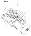
- the reference numeral 10 denotes a lock mechanism that locks the card 2 inserted into the card reader writer 1 so as to prevent pulling-out.
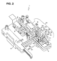
- the reference numeral 11 denotes a first beam, and the beam 11 is rotatably fixed to the housing 3 by inserting a shaft 21 through a hole 11a shown in Fig. 2 and a hole 3b formed in a projection 3a of the housing 3.
- the shaft 21, about which the first beam 11 turns, is referred below to as first fulcrum 21.
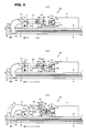
- the reference numeral 11c denotes a pawl formed on a tip end of the first beam 11. When the first beam 11 turns about the first fulcrum 21 as described later, the pawl 11c springs into a passage 20 (shown in, for example, Fig. 3(a)) of the card 2 to block the passage 20, or retreats from the passage 20 of the card 2 to clear the passage 20.
- the reference numeral 7 shown in Fig. 1 denotes a solenoid fixed to the housing 3, and 8 a plunger provided in the solenoid 7.
- the solenoid 7 attracts the plunger 8 to move the same in the direction A in which the card 2 is inserted. Then, when driving is stopped, the solenoid 7 ceases attracting the plunger 8.
- the reference numeral 9 denotes a spring having an elastic force (here, expanding force) smaller than the attractive force of the solenoid 7 and biasing the plunger 8 in the direction B in which the card 2 is pulled out.
- the fourth beam 14 By providing the fourth beam 14 as described above, when the solenoid 7 attracts the plunger 8 in the direction A, the fourth beam 14 is moved in the direction A as described later to cause the second beam 12 to turn about the second fulcrum 22. That is, the solenoid 7 turns the second beam 12 via the plunger 8 and the fourth beam 14. Also, when the solenoid 7 releases attraction of the plunger 8, the spring 9 biases the plunger 8 in the direction B whereby the fourth beam 14 is moved in the direction B as described later to cause the second beam 12 to turn about the second fulcrum 22 in a direction opposed to that when the plunger 8 is attracted. That is, the spring 9 turns the second beam 12 via the plunger 8 and the fourth beam 14 in a direction opposed to that when the solenoid 7 is driven.
- the first beam 11 constitutes an embodiment of a first beam in the invention
- the second beam 12 constitutes an embodiment of a second beam in the invention
- the third beam 13 constitutes an embodiment of a third beam in the invention.
- the first fulcrum 21 constitutes an embodiment of a first fulcrum in the invention
- the second fulcrum 22 constitutes an embodiment of a second fulcrum in the invention
- the first joint 31 constitutes an embodiment of a first joint in the invention
- the second joint 32 constitutes an embodiment of a second joint in the invention.
- the solenoid 7, the spring 9, and the fourth beam 14 constitute an embodiment of an actuator in the invention.
- the stopper 16 constitutes an embodiment of a stopper in the invention.
- the solenoid 7 is supplied with an electric current to be magnetized and attract the plunger 8 with a force F2 in the direction A.
- the fourth beam 14 is pulled by the plunger 8 in the direction A, an angular moment M2 acts on the second beam 12 via the third joint 14b, and the second beam 12 is turned about the second fulcrum 22 in direction L.
- the third beam 13 is pushed via the second joint 32 by the second beam 12 with a force F4, and the movement of the third beam 13 turns the first beam 11 with an angular moment M4 about the first fulcrum 21 via the first joint 31 in direction Q. Therefore, the pawl 11c springs into the passage 20 as shown in Fig. 3(c). Then, when the solenoid 7 fully attracts the plunger 8 in the direction A, movements of the respective beams 11 to 14 cause the pawl 11c to spring further into the passage 20 to completely block the passage 20 as shown in Fig. 4(d). This state is one in which the card 2 is locked so that it cannot be pulled out from within the card reader writer 1.
- the card reader writer 1 When in the locked state, the card reader writer 1 brings the IC contacts 5a (Fig. 1) into contact with the IC contact 2a (Fig. 1) of the card 2 to perform the data processing on the card 2.
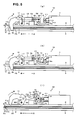
- a processing termination signal is fed to the card reader writer 1 from the information processing equipment, and the card reader writer 1 that receives the processing termination signal stops introduction of an electric current to the solenoid 7.
- the driving of the solenoid 7 is ended, releasing pull on the plunger 8 so that the plunger 8 is biased by the elastic force F1 of the spring 9 in the direction B as shown in fig. 4(e).
- the joints 31, 32, and the second fulcrum 22, which are aligned on the straight line X can be prevented from getting out of alignment on the straight line X, and the third beam 13 is not moved further.
- the third beam 13 is not moved as described above, the first beam 11 is not turned about the first fulcrum 21 in the direction P, and the pawl 11c blocking the passage 20 will not be cleared from the passage 20. That is, by virtue of the above, locking will not be released even when the card 2 is pulled while the data processing is performed on the card 2.
- frictional forces on the respective fulcrums 21, 22, 14a and the respective joints 31, 32, 14b serve as forces to obstruct turning of the second beam 12 and movements of the third beam 13 but all the shafts and the shaft portions which constitute such parts are small in radius of rotation, and so the frictional forces are minute and have little influence.
- the lock mechanism 10 can be made small in height to make the card reader writer 1 small in size.
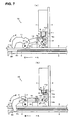
- the elastic force F1 of the spring 9 causes the second beam 12 to turn via the fourth beam 14 about the second fulcrum 22 in the direction L to move the third beam 13 downward. Therefore, the first beam 11 turns about the first fulcrum 21 in the direction P, so that the pawl 11c is cleared from the passage 20 as shown in Fig. 6(a) to put the card 2 in a released state.
- a lock mechanism 70 shown in Fig. 7 may be used, in which a solenoid 7 is mounted so that the direction of movements of a plunger 8 is perpendicular to the passage 20.
- the same parts in Fig. 7 as the respective parts shown in Figs. 3 to 5 are denoted by the same reference numerals.
- a second beam may be mounted at a tip end of the plunger so that the attractive force of the solenoid is imparted directly to the second beam from the plunger.
- one end of the spring may be mounted to the second beam and the other end of the spring may be mounted to the housing so that the elastic force of the spring be imparted directly to the second beam to bias the second beam in a predetermined turning direction.
Landscapes
- Physics & Mathematics (AREA)
- General Physics & Mathematics (AREA)
- Engineering & Computer Science (AREA)
- Theoretical Computer Science (AREA)
- Conveying Record Carriers (AREA)
- Details Of Connecting Devices For Male And Female Coupling (AREA)
Applications Claiming Priority (2)
| Application Number | Priority Date | Filing Date | Title |
|---|---|---|---|
| JP2003201570A JP4079843B2 (ja) | 2003-07-25 | 2003-07-25 | カード処理装置 |
| JP2003201570 | 2003-07-25 |
Publications (3)
| Publication Number | Publication Date |
|---|---|
| EP1501042A2 true EP1501042A2 (fr) | 2005-01-26 |
| EP1501042A3 EP1501042A3 (fr) | 2006-04-05 |
| EP1501042B1 EP1501042B1 (fr) | 2012-06-13 |
Family
ID=33487662
Family Applications (1)
| Application Number | Title | Priority Date | Filing Date |
|---|---|---|---|
| EP04016176A Expired - Lifetime EP1501042B1 (fr) | 2003-07-25 | 2004-07-09 | Unité de traitement de carte |
Country Status (4)
| Country | Link |
|---|---|
| EP (1) | EP1501042B1 (fr) |
| JP (1) | JP4079843B2 (fr) |
| BR (1) | BRPI0402991B1 (fr) |
| ES (1) | ES2385979T3 (fr) |
Cited By (2)
| Publication number | Priority date | Publication date | Assignee | Title |
|---|---|---|---|---|
| WO2007110100A1 (fr) * | 2006-03-29 | 2007-10-04 | Fci | Lecteur de carte dote d'un mecanisme d'ejection de carte |
| WO2015059719A1 (fr) * | 2013-10-25 | 2015-04-30 | Te Connectivity India Private Limited | Lecteur de carte |
Families Citing this family (3)
| Publication number | Priority date | Publication date | Assignee | Title |
|---|---|---|---|---|
| WO2008149529A1 (fr) | 2007-06-01 | 2008-12-11 | Nidec Sankyo Corporation | Dispositif de traitement de carte |
| JP2016122376A (ja) * | 2014-12-25 | 2016-07-07 | 日本電産サンキョー株式会社 | カードリーダ |
| KR102724176B1 (ko) * | 2024-03-05 | 2024-10-31 | 주식회사 부민더블유엔피(W&P) | 무선통신성능을 향상시킨 결제처리유닛을 구비한 음식물 쓰레기 종량제 수거장치 |
Family Cites Families (4)
| Publication number | Priority date | Publication date | Assignee | Title |
|---|---|---|---|---|
| EP0363992B1 (fr) * | 1988-10-14 | 1996-04-03 | Omron Corporation | Lecteur de carte pourvu d'un mécanisme de verrouillage |
| JP2539678B2 (ja) * | 1989-02-15 | 1996-10-02 | 松下電器産業株式会社 | Icカ―ドリ―ダ・ライタ |
| JP3490285B2 (ja) * | 1998-03-11 | 2004-01-26 | 株式会社三協精機製作所 | カードリーダ |
| JP3362691B2 (ja) * | 1999-03-08 | 2003-01-07 | 松下電器産業株式会社 | Icカードリーダ |
-
2003
- 2003-07-25 JP JP2003201570A patent/JP4079843B2/ja not_active Expired - Fee Related
-
2004
- 2004-07-09 ES ES04016176T patent/ES2385979T3/es not_active Expired - Lifetime
- 2004-07-09 EP EP04016176A patent/EP1501042B1/fr not_active Expired - Lifetime
- 2004-07-23 BR BRPI0402991A patent/BRPI0402991B1/pt not_active IP Right Cessation
Non-Patent Citations (1)
| Title |
|---|
| None |
Cited By (2)
| Publication number | Priority date | Publication date | Assignee | Title |
|---|---|---|---|---|
| WO2007110100A1 (fr) * | 2006-03-29 | 2007-10-04 | Fci | Lecteur de carte dote d'un mecanisme d'ejection de carte |
| WO2015059719A1 (fr) * | 2013-10-25 | 2015-04-30 | Te Connectivity India Private Limited | Lecteur de carte |
Also Published As
| Publication number | Publication date |
|---|---|
| BRPI0402991A (pt) | 2005-03-22 |
| JP4079843B2 (ja) | 2008-04-23 |
| JP2005044063A (ja) | 2005-02-17 |
| EP1501042A3 (fr) | 2006-04-05 |
| EP1501042B1 (fr) | 2012-06-13 |
| ES2385979T3 (es) | 2012-08-06 |
| BRPI0402991B1 (pt) | 2016-07-12 |
Similar Documents
| Publication | Publication Date | Title |
|---|---|---|
| US6270365B1 (en) | IC card connector having IC card ejection mechanism | |
| JP4246208B2 (ja) | ロック装置及びそれを備えたコネクタ装置 | |
| US6338636B2 (en) | IC card connector having IC card ejection mechanism | |
| EP1324256A1 (fr) | Connecteur de carte | |
| EP1501042B1 (fr) | Unité de traitement de carte | |
| JP3362691B2 (ja) | Icカードリーダ | |
| CN107085735B (zh) | 读卡器 | |
| US10402705B2 (en) | Card reader | |
| US7556195B2 (en) | Card reader and writer | |
| US20110121078A1 (en) | Card reader | |
| US6295180B1 (en) | Disk drive capable of preventing ejection of magnetic recording medium even upon erroneous depression of eject button during work | |
| JP3204646B2 (ja) | Icカードリーダライタおよびicカードリーダライタのインターロック方法 | |
| US7827570B2 (en) | Cartridge locking mechanism and tray locking mechanism for cartridge drive apparatus | |
| US12180020B2 (en) | Image processing apparatus | |
| JPS63282989A (ja) | メモリ−カ−トリツジのドライブ装置 | |
| JP3505647B2 (ja) | カード用コネクタのイジェクトロック機構 | |
| JP3109494B2 (ja) | Icカードリーダライタのインターロック機構 | |
| US20190164023A1 (en) | Card Reader | |
| JPH01219973A (ja) | Icカードの取り出し防止装置 | |
| JP3466496B2 (ja) | カード用コネクタ | |
| JP4473194B2 (ja) | 記録メディア駆動装置 | |
| JPH0650540B2 (ja) | Icカードリーダライタ | |
| JPH03290778A (ja) | Icカードリーダライタのカード排出機構 | |
| JPH04112286A (ja) | Icカードリーダライタのイジェクト機構 | |
| JPH01219979A (ja) | Icカード排出時の保護装置 |
Legal Events
| Date | Code | Title | Description |
|---|---|---|---|
| PUAI | Public reference made under article 153(3) epc to a published international application that has entered the european phase |
Free format text: ORIGINAL CODE: 0009012 |
|
| AK | Designated contracting states |
Kind code of ref document: A2 Designated state(s): AT BE BG CH CY CZ DE DK EE ES FI FR GB GR HU IE IT LI LU MC NL PL PT RO SE SI SK TR |
|
| AX | Request for extension of the european patent |
Extension state: AL HR LT LV MK |
|
| PUAL | Search report despatched |
Free format text: ORIGINAL CODE: 0009013 |
|
| AK | Designated contracting states |
Kind code of ref document: A3 Designated state(s): AT BE BG CH CY CZ DE DK EE ES FI FR GB GR HU IE IT LI LU MC NL PL PT RO SE SI SK TR |
|
| AX | Request for extension of the european patent |
Extension state: AL HR LT LV MK |
|
| RAP1 | Party data changed (applicant data changed or rights of an application transferred) |
Owner name: HITACHI-OMRON TERMINAL SOLUTIONS, CORP. |
|
| 17P | Request for examination filed |
Effective date: 20060929 |
|
| AKX | Designation fees paid |
Designated state(s): DE ES FR GB |
|
| 17Q | First examination report despatched |
Effective date: 20070126 |
|
| GRAP | Despatch of communication of intention to grant a patent |
Free format text: ORIGINAL CODE: EPIDOSNIGR1 |
|
| RIN1 | Information on inventor provided before grant (corrected) |
Inventor name: NAKABO, AKINOBUC/O OMRON CORP. |
|
| GRAS | Grant fee paid |
Free format text: ORIGINAL CODE: EPIDOSNIGR3 |
|
| GRAA | (expected) grant |
Free format text: ORIGINAL CODE: 0009210 |
|
| AK | Designated contracting states |
Kind code of ref document: B1 Designated state(s): DE ES FR GB |
|
| REG | Reference to a national code |
Ref country code: GB Ref legal event code: FG4D |
|
| REG | Reference to a national code |
Ref country code: ES Ref legal event code: FG2A Ref document number: 2385979 Country of ref document: ES Kind code of ref document: T3 Effective date: 20120806 |
|
| REG | Reference to a national code |
Ref country code: DE Ref legal event code: R096 Ref document number: 602004038149 Country of ref document: DE Effective date: 20120809 |
|
| PLBE | No opposition filed within time limit |
Free format text: ORIGINAL CODE: 0009261 |
|
| STAA | Information on the status of an ep patent application or granted ep patent |
Free format text: STATUS: NO OPPOSITION FILED WITHIN TIME LIMIT |
|
| 26N | No opposition filed |
Effective date: 20130314 |
|
| REG | Reference to a national code |
Ref country code: DE Ref legal event code: R097 Ref document number: 602004038149 Country of ref document: DE Effective date: 20130314 |
|
| REG | Reference to a national code |
Ref country code: FR Ref legal event code: PLFP Year of fee payment: 13 |
|
| PGFP | Annual fee paid to national office [announced via postgrant information from national office to epo] |
Ref country code: ES Payment date: 20160613 Year of fee payment: 13 |
|
| PGFP | Annual fee paid to national office [announced via postgrant information from national office to epo] |
Ref country code: FR Payment date: 20160613 Year of fee payment: 13 |
|
| PGFP | Annual fee paid to national office [announced via postgrant information from national office to epo] |
Ref country code: DE Payment date: 20160705 Year of fee payment: 13 Ref country code: GB Payment date: 20160706 Year of fee payment: 13 |
|
| REG | Reference to a national code |
Ref country code: DE Ref legal event code: R119 Ref document number: 602004038149 Country of ref document: DE |
|
| GBPC | Gb: european patent ceased through non-payment of renewal fee |
Effective date: 20170709 |
|
| REG | Reference to a national code |
Ref country code: FR Ref legal event code: ST Effective date: 20180330 |
|
| PG25 | Lapsed in a contracting state [announced via postgrant information from national office to epo] |
Ref country code: GB Free format text: LAPSE BECAUSE OF NON-PAYMENT OF DUE FEES Effective date: 20170709 Ref country code: DE Free format text: LAPSE BECAUSE OF NON-PAYMENT OF DUE FEES Effective date: 20180201 |
|
| PG25 | Lapsed in a contracting state [announced via postgrant information from national office to epo] |
Ref country code: FR Free format text: LAPSE BECAUSE OF NON-PAYMENT OF DUE FEES Effective date: 20170731 |
|
| REG | Reference to a national code |
Ref country code: ES Ref legal event code: FD2A Effective date: 20181106 |
|
| PG25 | Lapsed in a contracting state [announced via postgrant information from national office to epo] |
Ref country code: ES Free format text: LAPSE BECAUSE OF NON-PAYMENT OF DUE FEES Effective date: 20170710 |