EP1501051A2 - Gerät und Verfahren zur Erfassung der Lage und der Orientierung - Google Patents
Gerät und Verfahren zur Erfassung der Lage und der Orientierung Download PDFInfo
- Publication number
- EP1501051A2 EP1501051A2 EP04254058A EP04254058A EP1501051A2 EP 1501051 A2 EP1501051 A2 EP 1501051A2 EP 04254058 A EP04254058 A EP 04254058A EP 04254058 A EP04254058 A EP 04254058A EP 1501051 A2 EP1501051 A2 EP 1501051A2
- Authority
- EP
- European Patent Office
- Prior art keywords
- orientation
- image
- sensing apparatus
- coordinates
- image sensing
- Prior art date
- Legal status (The legal status is an assumption and is not a legal conclusion. Google has not performed a legal analysis and makes no representation as to the accuracy of the status listed.)
- Withdrawn
Links
Images

Classifications
-
- G—PHYSICS
- G06—COMPUTING OR CALCULATING; COUNTING
- G06T—IMAGE DATA PROCESSING OR GENERATION, IN GENERAL
- G06T7/00—Image analysis
- G06T7/70—Determining position or orientation of objects or cameras
- G06T7/73—Determining position or orientation of objects or cameras using feature-based methods
-
- G—PHYSICS
- G06—COMPUTING OR CALCULATING; COUNTING
- G06T—IMAGE DATA PROCESSING OR GENERATION, IN GENERAL
- G06T7/00—Image analysis
- G06T7/80—Analysis of captured images to determine intrinsic or extrinsic camera parameters, i.e. camera calibration
-
- G—PHYSICS
- G06—COMPUTING OR CALCULATING; COUNTING
- G06T—IMAGE DATA PROCESSING OR GENERATION, IN GENERAL
- G06T2207/00—Indexing scheme for image analysis or image enhancement
- G06T2207/30—Subject of image; Context of image processing
- G06T2207/30244—Camera pose
Definitions
- the present invention relates to position and orientation detection technique for detecting a position and orientation of an image sensing apparatus equipped with an image sensor for sensing images in real space and an orientation change detector for detecting the extent of a change in orientation.
- Detection of the position and orientation of an image sensing unit such as a camera that senses images in real space is necessary to a mixed reality system that combines real space and virtual space and displays combined space (hereinafter “mixed reality space”).
- method 3 many different methods of obtaining the position and orientation of the camera from just the information obtained by the camera sensing indicators that exist in real space (scene) with the camera are being implemented. These methods, which do not use sensors other than the camera, are hereinafter collectively referred to as method 3.
- Method 3 is a method that detects the position and orientation of the camera solely by image processing, and thus suffers from an inability to track in cases that the position of the indicators change dramatically from one frame to the next, due, for example, to rapid movement of the head.
- the method takes inertial sensor detection values and the position of coordinates detected from the image as the source of data input, directly applies such data to the extended Kalman filter, and predictively estimates the present position and orientation of the camera (since the position of the indicator obtained from the inertial sensors and the image is data obtained previously using the present camera position and orientation as the reference standard, an estimate of the present position and orientation can be obtained predictively).
- This method by using sensor detection data obtained continuously without a break over a continuous period of time at precisely determined intervals as well as indicator data detected from the image to predict the continuous movement of the camera, estimates the position and orientation of the camera.
- Method 1 as has been made problematic already in method 2, using only a 6-DOF sensor gives rise to the problem that the accuracy of the position and orientation obtained is inadequate.
- a 6-DOF sensor generally requires a separate apparatus mounted in real space (excluding the camera) for outputting signals for detection by the sensor unit mounted on the camera.
- a separate apparatus mounted in real space (excluding the camera) for outputting signals for detection by the sensor unit mounted on the camera.
- an apparatus that generates a magnetic field for detection by a sensor mounted on the detection target corresponds to this separate apparatus
- a photoreceptor or photo-generator unit corresponds to this separate apparatus. That such a separate apparatus is required means that the detection range of the sensor is restricted to a limited range.
- Method 2 is a method proposed in light of the drawbacks of method 1, in particular the inability to obtain adequate detection accuracy, and solves the problem of poor detection accuracy.
- the method uses a 6-DOF sensor, the problems of detection range, installation and cost remain unresolved.
- each indicator when detecting the indicators from the image, in some instances there might be a problem with the detectional stability of the indicators.
- each indicator in order to stabilize the detection of the indicators, each indicator must be large enough to enable that particular indictor to be identified and defined on its own, and moreover, that indicator must occupy a sufficiently large surface area within the image acquired by the camera.
- a large indicator cannot always be installed in real space.
- Method 4 was conceived in light of the indicator detection stability problem of method 3. However, with method 4, prior to indicator detection from the image a gyro sensor is used solely for the purpose of predicting the position of the indicator, and with respect to everything else besides increasing indicator detection stability, method 4 retains the same problems that plague method 3. It should be noted that, in method 4, data obtained by the gyro sensor is not used in the computations used to estimate the position and orientation of the camera, and thus method 4 is the same as method 3 with respect to the computations performed to estimate the position and orientation of the camera. An inertial sensor such as a gyro sensor does not required a separate apparatus that must be disposed within real space, and therefore method 4 escapes the problems of detection range and installation that affect methods 1 and 2. In addition, because of its low cost in general, method 4 also solves the problem of cost associated with method 1 and method 2.
- Method 5 unlike methods 1 through 4 described above, estimates the position and orientation of the camera continuously, without interruption, at precise intervals over a continuous period of time. With method 5, it is necessary to acquire data continuously at a certain interval, and moreover, it is necessary to estimate continuously at a certain interval.
- a process of uncertain required time i.e., virtual space rendering is included in the processing
- the position and orientation of the camera at the time a rendering is completed cannot be predicted when computations are performed using the extended Kalman filter, and thus does not always function effectively.
- the present invention is conceived in consideration of the above-described conventional art, and has as its object to obtain high-accuracy detection results using a simplified configuration in position and orientation detection.
- position and orientation detection method of detecting a position and orientation of an image sensing apparatus that senses real space comprising: an orientation change detection step of detecting an extent of change in orientation of the image sensing apparatus; a first image coordinates computation step of obtaining coordinates in an image of indicators included in a real space image sensed by the image sensing apparatus; a position and orientation estimation step of estimating a present position and orientation of the image sensing apparatus based on position and orientation of the image sensing apparatus obtained previously and the extent of change in orientation of the image sensing apparatus obtained in the orientation change detection step; a second image coordinates computation step of obtaining coordinates of indicators in a sensed image display screen of the image sensing apparatus at the position and orientation obtained in the position and orientation estimation step; and a position and orientation correction step of correcting the position and orientation estimated in the position and orientation estimation step using a correction method adapted to the amount of data obtained from the coordinates of the indicators obtained in the first image coordinates computation step and the coordinates
- a position and orientation detection apparatus for detecting a position and orientation of an image sensing apparatus that senses real space
- the apparatus comprising: an orientation change detection unit adapted to detect an extent of change in orientation of the image sensing apparatus; a first image coordinates computation unit adapted to obtain coordinates in an image of indicators includes in a real space image sensed by the image sensing apparatus; a position and orientation estimation unit adapted to estimate a present position and orientation of the image sensing apparatus based on position and orientation of the image sensing apparatus obtained previously and the extent of change in orientation of the image sensing apparatus obtained by the orientation change detection unit; a second image coordinates computation unit adapted to obtain coordinates of indicators in a sensed image display screen of the image sensing apparatus at the position and orientation obtained by the position and orientation estimation unit; and a position and orientation correction unit adapted to correct the position and orientation estimated by the position and orientation estimation unit using a correction method adapted to the amount of data obtained from the coordinates of the indicators obtained by the first image coordinates computation unit and
- a position and orientation detection method of detecting a position and orientation of an image sensing apparatus that senses real space comprising: an orientation change detection step of detecting an extent of change in orientation of the image sensing apparatus; a first image coordinates computation step of obtaining coordinates in an image of indicators included in a real space image sensed by the image sensing apparatus; a position and orientation estimation step of estimating a present position and orientation of the image sensing apparatus based on position and orientation of the image sensing apparatus obtained previously and the extent of change in orientation of the image sensing apparatus obtained in the orientation change detection step; a second image coordinates computation step of obtaining coordinates of indicators in a sensed image display screen of the image sensing apparatus at the position and orientation obtained in the position and orientation estimation step; and a position and orientation computation step of computing a present position and orientation from the coordinates of the indicators obtained in the first image coordinates computation step and the coordinates of the indicators obtained in the second image coordinates computation step.
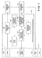
- Fig. 1 shows the functional configuration of a case in which a position and orientation detection apparatus 100 according to the present embodiment is adapted to a Head Mounted Display (HMD) 101.
- the HMD 101 has a camera 102, an angular speed sensor 103 and a display unit 104, and can be moved through real space.
- the camera 102 senses the real space and outputs signals expressing a sensed image to a sensed image acquisition unit 105.
- the angular speed sensor 103 based on vibration gyro and other principles, detects the angular speed of movement of the HMD 101.
- the display unit 104 is a display unit capable of displaying an image, and is typically constructed of two display units, one for the right eye and one for the left eye.
- the present embodiment employs a HMD 101 of which the positions of each of the camera 102, the angular speed sensor 103 and the display unit 104 are fixed, provided that the positions of the camera 102 and the angular speed sensor 103 are fixed in relation to each other and can move through real space, the display unit 104 need not be fixed in relation to the camera 102 and the angular speed sensor 103, and need not be built into the HMD 101.
- the sensed image acquisition unit 105 which receives signals transmitted from the camera 102 and generates image data.
- the image data thus obtained is sent to a characteristic feature detection unit 106 as well as to a sensed image rendering unit 111.
- the characteristic feature detection unit 106 is adapted to detect indicators (which may be previously arranged markers, or characteristic features such as buildings or some other distinctive topographical feature) in real space that are included in the image data input from the sensed image acquisition unit 105. At this time, the position of the indicator in the image (that is, the 2-dimensional coordinates of the indicator within the image)is also detected.
- a position and orientation update processor 107 updates (information expressing) position and orientation by computing the extent of a change in orientation from angular speed signals from the angular speed sensor 103 and an elapsed time obtained, for example, by time processing using a clock signal inside the apparatus and simply adding this extent of change to a camera position and orientation initial value 108 or to a past value stored in a position and orientation buffer 110.
- a camera position and orientation estimation calculator 109 projects a 3-dimensional position of the indicator in real space onto the image display and estimates the position and orientation of the camera based on the superimposed points of the indicator on the image thus obtained and the position of detection on the image display of the indictor as obtained by the characteristic feature detection unit 106. A detailed description of the estimation process is given later.
- the position and orientation of the camera obtained by the camera position and orientation estimation calculator 109 is held in the position and orientation buffer 110 and also sent to a virtual space superimposing unit 112.
- the position and orientation buffer 110 is the buffer that stores the position and orientation of the camera obtained by the camera position and orientation estimation calculator 109, and the position and orientation so stored is used by the position and orientation update processor 107 as described above.
- the sensed image rendering unit 111 and the virtual space mixed rendering unit 112 are examples of apparatuses that use the position and orientation of the camera output by the position and orientation detection apparatus 100 according to the present embodiment, and are compositional elements unrelated to position and orientation detection.
- the sensed image rendering unit 111 like the characteristic feature detection unit 106, takes image data obtained by the sensed image acquisition unit 105 and renders this image data, which is the result of sensing real space, to a display buffer (not shown) of the display unit 104.
- the virtual space superimposing unit 112 carries out mixed rendering of virtual space by rewrite rendering of virtual space (a virtual object image) to the buffer rendered by the sensed image rendering unit 111 and the same display buffer. More specifically, the virtual space superimposing unit 112 combines real space (a real space image) sensed by the camera 102 and virtual space (a virtual object image) generated by rendering a predetermined virtual space model based on the camera position and orientation obtained by the camera position and orientation estimation calculator 109.
- the virtual space superimposing unit 112 transmits the contents of the display buffer to the display unit 104 built into the HMD 101, so that the mixed rendering results are displayed on the display unit 104.
- the position and orientation detection apparatus 100 having the above-described configuration can be placed in any location without regard to the range through which the HMD 101 moves, and thus is very different from the separate apparatus required when using a 6-DOF sensor.
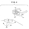
- Fig. 2 is a schematic diagram showing a use environment of the HMD 101 according to the present embodiment shown in Fig. 1.
- the camera 102 is built into the HMD 101
- the angular speed sensor 103 is mounted on the HMD 101
- the display unit 104 is built into the HMD 101.
- This HMD 101 can move freely through real space, and markers 204 that serve as indicators are arranged in the real space that is the target of observation.
- the indicators are points whose positioning in three dimensions (3-dimensional positions) in real space are known, and further, are distinctive enough to be detectable by the characteristic feature detection unit 106 from an image in which the indicators are sensed.
- the shape and color of the markers 204, or their surface area can be set so as to be detectable by the characteristic feature detection unit 106 from an image in which the indicators are sensed.
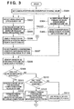
- Figs. 3 and 4 are flow charts of the main processing of the present embodiment. These two diagrams are divided into two sheets of paper simply for the sake of convenience, and are really a single flow chart as shown connected by the flow chart connector.
- an initial position and orientation of the camera is set.
- the initial position and orientation of the camera is an initial value of the position and orientation of the camera used in succeeding steps in the process, and expresses the approximate position and orientation of the camera at the time of implementation of the present embodiment.
- step S301 As an initial position and orientation that can be used in step S301, for example, on the assumption that the position and orientation of the camera when the apparatus is first engaged will not change greatly, it is possible to use a value stored as a predetermined constant.
- the initial value for the position and orientation of the camera which is the camera position and orientation initial value 108, is set as the position and orientation of the camera.
- a position and orientation of the camera estimated using the features of an image sensed by a camera (the camera 102), the camera being the position and orientation detection target.
- a marker that makes it possible to estimate the 6-DOF of the position and orientation of the camera can be used in addition to and separate from the markers 204 in Fig. 2 but placed near the markers 204. Then, processing begins in a state in which the camera is set so that the marker for setting the initial position and orientation is sensed, and the position and orientation of the camera is estimated from the marker for setting the initial position and orientation sensed by the camera and used as the initial position and orientation and in step S301.
- Step S302 is a step that is continuously executed in tandem with a step S303 to be described later
- step S304 is a step continuously executed by this step alone.
- a process of acquiring video from the camera 102 is executed using the sensed image acquisition unit 105.
- the camera 102 continues to sense images of continuous frames over a continuous period of time.
- the acquisition step involves acquiring a signal of a single page of an image at a particular moment in time within the continuous frames.
- a trigger is generated that indicates that acquisition of an image to be used in the step S303 to be described below is finished.
- the acquired image data is used in the process carried out in a step S305.
- the processing of step S304 is repeated in order to acquire the next frame immediately after finishing acquisition of a single display screen's worth of an image.
- step S304 continuously acquires image data from the camera and generates a trigger when a page of image data has been acquired.
- step S302 detection of angular speed is carried out using the angular speed sensor 103.
- step S303 the angular speed detected in step S302 is added to the elapsed time.
- the elapsed time is the interval at which the adding process in step S303 is carried out, and is a tiny time period that adds together the detection of step S302 and the computation time of step S303.
- steps S302 and S303 are executed repeatedly (recursively), and the angular speed calculated in step S302 is from time to time added up in step S303.
- step S303 does not simply continue adding but, using the trigger generated at step S304 after acquiring a page of an image, transfers the sum of the addition at the time that trigger is received to a step S306, and the sum value is reset to 0.
- step S306 when the data transferred from step S303 is received, that is, when the trigger of step S304 is received as input at step S303 and a sum value is output, the sum value of the angular speed obtained in step S303 is added to the position and orientation of the camera stored at that time to calculate a new camera position and orientation.
- the camera position and orientation used when commencing operation and executing step S306 for the first time is the initial value of the position and orientation of the camera set in step S301. As is described later, after completing the following steps, this step S306 is executed once again, at which stage the position and orientation of the camera is calculated by steps to be described below.
- step S307 using the camera position and orientation obtained in step S306, the 3-dimensional positions of the markers 204 disposed within a scene (real space) sensed at that position and orientation are projected onto the 2-dimensional positions on the image display screen obtained by the camera.
- This superimposition can be calculated from two processes, or steps: A viewing transformation step that converts the coordinates of the markers disposed within the scene within a global coordinate system into a camera coordinate system, that is, to coordinate values in a 3-dimensional coordinate system that takes the position of the camera as the origin and whose axes change orientation depending on the orientation of the camera; and a see-through projection conversion step that superimposes the coordinates of the camera coordinate system onto the image display screen.
- a viewing transformation step that converts the coordinates of the markers disposed within the scene within a global coordinate system into a camera coordinate system, that is, to coordinate values in a 3-dimensional coordinate system that takes the position of the camera as the origin and whose axes change orientation depending on the orientation of the camera
- a see-through projection conversion step that
- a viewing transformation is a transformation that corresponds to the inverse transformation of the coordinate transformation expressed by equation (1).
- this R and t are not the camera position and orientation detection values themselves (they are the inverse transformation of the rotation component and the translational movement component).
- the camera coordinate system coordinates can be calculated from the markers' global coordinate system coordinates using the positions of the markers.
- f x and f y are the focal lengths of the camera in the direction of the x-axis and in the direction of the y-axis, respectively.
- the focal length is expressed as two values.
- the focal length is a value unique to the camera, and is considered to have been obtained previously.
- the computations for superimposing the 3-dimensional positions of the markers onto the image display screen carried out in step S307 involve a process of treating the coordinates of the markers on the global coordinate system as X W and computing a position U on the image display screen using equation (7).
- a step S308 the superimposed positions of the markers on the image display screen obtained in step S307 and the positions of the markers in the image being obtained in step S305 are compared, and those pairs of markers that are sufficiently close to each other on the image display screen are identified as the same marker.
- step S309 as one example of determining whether there is enough correctible data for all 6 DOF of the position and orientation of the camera obtained in step S306, it is determined whether or not there are three or more markers (three pairs) that have been identified in step S308 as being the same. In the event that there are three or more such points, then processing proceeds to a step S311. By contrast, if there are two or fewer such points then processing proceeds to a step S310. That is, in step S310 a determination is made as to whether or not any more identified markers exist. If more identified markers do exist, then processing proceeds to a step S313. If not, then processing proceeds to a step S314.
- step S311 and S312 camera position and orientation are estimated using three or more identified markers (initial value correction).
- step S306 If the camera position and orientation obtained in step S306 were to express real values, then ⁇ S would be 0, and U i and V i would be the same point. However, since the camera position and orientation obtained in step S306 do not represent real values, U i and V i are not the same point.
- Obtaining the position and orientation of the camera involves estimating ⁇ S or S + ⁇ S based on the error between U i and V i .
- the Jacobi matrix from vector a of element j to vector b of element k is the matrix consisting of elements jxk, and is expressed as J ba .
- the elements of the three columns on the right side of the matrix in equation (12) become and can be obtained from the focal length and the positions of the indicators in the camera coordinate system.
- equation (14) in other words, the elements of the three columns on the left side of the matrix in equation (12), can be obtained from the positions of the indicators in the global coordinate system and the rotation axis rotation angle.
- Equation (15) means that tiny changes in U for tiny changes in S can be calculated using the J us obtained from the value for S at that time. From this it follows that, when ⁇ S is small, the actual extent of error ⁇ U and ⁇ S is:
- Equation (16) applies for each and every point, so using a vector that vertically aligns the vectors of n points yields:
- it can be applied as a computation of one part of a process of optimization carried out by repeating Newton's Method. That is, when there is a certain initial value S 0 , from the invariant positions x 1 , x 2 ... x n of the indicators within the global coordinate system and from the error vectors ⁇ U 1 ⁇ U 2 ... ⁇ U n , equation (19) can be used to obtained ⁇ S.
- step S311 a process of setting the camera position and orientation obtained in step S306 is carried out in order to provide the initial value necessary for the above-described recursive computation.
- the process of carrying out the recursive computation described above based on this value constitutes step S312.
- any recursive computation may be used as the method of obtaining the S at which the error (err) of equation (11) is smallest, and thus there is no requirement that only Newton's Method be used.
- the Levenberg-Marquardt(LM) Method or the Simplex Method can be used.
- the position and orientation of the camera at which all 6 DOF are optimal that is, the camera position and orientation is optimal, cannot be estimated.
- a process of correcting only either camera position 3 DOF (degree of freedom in the direction of rotation about the coordinate axes) or the camera position (degree of freedom in the translational direction of advance along the coordinate axes) is executed.
- a method is used that corrects the orientation or position so that that point matches perfectly. If there are two usable markers, then a method is used that uses an average correction extent so that both points match perfectly.
- step S314 because it is not possible to estimate and correct the position and orientation of the camera using markers, the camera position and orientation obtained in step S306 is taken directly as the present camera position and orientation.
- step S401 the image acquired by the sensed image acquisition unit 105 in step S304 is rendered using the sensed image rendering unit 111.
- step S402 using the camera position and orientation obtained by any of the methods of either step S312, step S313 or step S314, the virtual space superimposing unit 112 superimposes (renders by writing over) the virtual space (that is, the image of the virtual object) onto the sensed image rendering results to obtain a mixed rendering of real space and virtual space.
- step S403 the mixed rendering results thus obtained are displayed on the display unit 104, thus enabling an observer to observe a mixed image combining real space and virtual space. Thereafter, in a step S404, it is determined whether or not to end all processing.
- step S302 the processes of steps S302 and S303, as well as the process of step S304, are ended, ending all steps. If processing is not ended, that is, if the camera position and orientation are to continue to be detected and a mixed image displayed, then processing proceeds to step S306.
- step S306 the camera position and orientation obtained by any of the methods of steps S312, S313 and S314 are used to carry out processing based on the camera position and orientation obtained at the time that process is carried out.
- the position and orientation detection apparatus according to the present invention is adapted to the detection of the position and orientation of a camera mounted on a HMD.
- the position and orientation detection apparatus of the present invention can also be adapted to the detection of the position and orientation of any other image sensing apparatus.
- the present invention is not limited to the use of angular speed sensors. Provided that data that enables an estimate to be made of the present position and orientation to be made from a previously obtained position and orientation can be obtained, the signals of any sensor other than a 6 DOF sensor may be used instead.
- the invention can be implemented by supplying a software program, which implements the functions of the foregoing embodiments, directly or indirectly to a system or apparatus, reading the supplied program code with a computer of the system or apparatus, and then executing the program code.
- a software program which implements the functions of the foregoing embodiments
- reading the supplied program code with a computer of the system or apparatus, and then executing the program code.
- the mode of implementation need not rely upon a program.
- the program code installed in the computer also implements the present invention.
- the claims of the present invention also cover a computer program for the purpose of implementing the functions of the present invention.
- the program may be executed in any form, such as an object code, a program executed by an interpreter, or scrip data supplied to an operating system.
- Example of storage media that can be used for supplying the program are a floppy disk, a hard disk, an optical disk, a magneto-optical disk, a CD-ROM, a CD-R, a CD-RW, a magnetic tape, a non-volatile type memory card, a ROM, and a DVD (DVD-ROM and a DVD-R).
- a client computer can be connected to a website on the Internet using a browser of the client computer, and the computer program of the present invention or an automatically-installable compressed file of the program can be downloaded to a recording medium such as a hard disk.
- the program of the present invention can be supplied by dividing the program code constituting the program into a plurality of files and downloading the files from different websites.
- a WWW World Wide Web
- a storage medium such as a CD-ROM
- an operating system or the like running on the computer may perform all or a part of the actual processing so that the functions of the foregoing embodiments can be implemented by this processing.
- a CPU or the like mounted on the function expansion board or function expansion unit performs all or a part of the actual processing so that the functions of the foregoing embodiments can be implemented by this processing.
- the detection range, installation and cost problems associated with the 6-DOF sensor can be solved.
- the present invention detects the extent of change in the orientation of the camera, the indicator detection instability associated with methods that estimate position and orientation solely from the image obtained by the camera does not arise. Further, the camera position and orientation detection results do not stop at just indicator detection position prediction but can also be used directly in detecting the position and orientation of the camera. Moreover, there is no need to carry out predictive computations of the position and orientation at precise intervals as with methods that use an extended Kalman filter, making it possible to detect the position and orientation of the camera.
Landscapes
- Engineering & Computer Science (AREA)
- Computer Vision & Pattern Recognition (AREA)
- Physics & Mathematics (AREA)
- General Physics & Mathematics (AREA)
- Theoretical Computer Science (AREA)
- Length Measuring Devices By Optical Means (AREA)
- Studio Devices (AREA)
- Image Processing (AREA)
Applications Claiming Priority (2)
| Application Number | Priority Date | Filing Date | Title |
|---|---|---|---|
| JP2003193633A JP4532856B2 (ja) | 2003-07-08 | 2003-07-08 | 位置姿勢計測方法及び装置 |
| JP2003193633 | 2003-07-08 |
Publications (2)
| Publication Number | Publication Date |
|---|---|
| EP1501051A2 true EP1501051A2 (de) | 2005-01-26 |
| EP1501051A3 EP1501051A3 (de) | 2008-06-18 |
Family
ID=33487620
Family Applications (1)
| Application Number | Title | Priority Date | Filing Date |
|---|---|---|---|
| EP04254058A Withdrawn EP1501051A3 (de) | 2003-07-08 | 2004-07-07 | Gerät und Verfahren zur Erfassung der Lage und der Orientierung |
Country Status (4)
| Country | Link |
|---|---|
| US (1) | US7613356B2 (de) |
| EP (1) | EP1501051A3 (de) |
| JP (1) | JP4532856B2 (de) |
| CN (1) | CN100417197C (de) |
Cited By (4)
| Publication number | Priority date | Publication date | Assignee | Title |
|---|---|---|---|---|
| EP1596331A3 (de) * | 2004-05-14 | 2008-02-13 | Canon Kabushiki Kaisha | Verfahren und Vorrichtung zur Bestimmung der Position und Orientierung |
| DE102008023439A1 (de) * | 2008-05-14 | 2009-11-26 | Christian-Albrechts-Universität Zu Kiel | Augmented Reality Fernglas zur Navigationsunterstützung |
| WO2014099410A1 (en) * | 2012-12-21 | 2014-06-26 | Qualcomm Incorporated | Display of separate computer vision based pose and inertial sensor based pose |
| ES2543038A1 (es) * | 2014-12-23 | 2015-08-13 | Universidad De Cantabria | Método y sistema de localización espacial mediante marcadores luminosos para cualquier ambiente |
Families Citing this family (102)
| Publication number | Priority date | Publication date | Assignee | Title |
|---|---|---|---|---|
| US7046214B2 (en) * | 2003-12-17 | 2006-05-16 | Information Decision Technologies, Llc | Method and system for accomplishing a scalable, multi-user, extended range, distributed, augmented reality environment |
| EP1521213A3 (de) * | 2003-09-30 | 2006-08-30 | Canon Kabushiki Kaisha | Verfahren und Gerät zur Indexidentifizierung |
| DE102004047519B4 (de) * | 2004-09-28 | 2021-08-12 | Leica Microsystems Cms Gmbh | Verfahren zur Überlagerung optischer Informationen bei einem Scan-Mikroskop |
| JP5127128B2 (ja) * | 2004-12-21 | 2013-01-23 | 韓國電子通信研究院 | カメラの位置及び姿勢情報補正方法及びその装置 |
| JP4859205B2 (ja) * | 2005-02-04 | 2012-01-25 | キヤノン株式会社 | 情報処理装置、情報処理方法、及びプログラム |
| JP4914019B2 (ja) * | 2005-04-06 | 2012-04-11 | キヤノン株式会社 | 位置姿勢計測方法及び装置 |
| CN1855273A (zh) * | 2005-04-06 | 2006-11-01 | 索尼株式会社 | 再现装置、设定改变方法和设定改变装置 |
| EP1739622B1 (de) * | 2005-06-28 | 2013-08-14 | Canon Kabushiki Kaisha | Erkennung eines Bildmerkmals mit Hilfe zweier Kameras |
| JP4574473B2 (ja) | 2005-07-11 | 2010-11-04 | キヤノン株式会社 | 情報処理装置および方法 |
| IL169934A (en) * | 2005-07-27 | 2013-02-28 | Rafael Advanced Defense Sys | Real-time geographic information system and method |
| FR2889761A1 (fr) * | 2005-08-09 | 2007-02-16 | Total Immersion Sa | Systeme permettant a un utilisateur de localiser une camera afin de pouvoir inserer, rapidement de maniere ajustee, des images d'elements virtuels dans des images video d'elements reels captees par la camera |
| JP5084167B2 (ja) * | 2006-03-31 | 2012-11-28 | キヤノン株式会社 | 位置姿勢計測方法及び装置 |
| JP5403861B2 (ja) | 2006-11-06 | 2014-01-29 | キヤノン株式会社 | 情報処理装置、情報処理方法 |
| JP5132138B2 (ja) | 2006-11-28 | 2013-01-30 | キヤノン株式会社 | 位置姿勢計測方法、位置姿勢計測装置 |
| JP4960754B2 (ja) * | 2007-04-25 | 2012-06-27 | キヤノン株式会社 | 情報処理装置、情報処理方法 |
| JP5013961B2 (ja) * | 2007-05-21 | 2012-08-29 | キヤノン株式会社 | 位置姿勢計測装置及びその制御方法 |
| CA2717745A1 (en) * | 2008-03-07 | 2009-09-11 | Intelligent Spatial Technologies, Inc. | Mobile device and geographic information system background and summary of the related art |
| JP5195041B2 (ja) * | 2008-05-30 | 2013-05-08 | 富士ゼロックス株式会社 | 指示装置、対象物認識装置およびプログラム |
| JP5047090B2 (ja) | 2008-07-31 | 2012-10-10 | キヤノン株式会社 | システム |
| US9600067B2 (en) * | 2008-10-27 | 2017-03-21 | Sri International | System and method for generating a mixed reality environment |
| KR101199492B1 (ko) | 2008-12-22 | 2012-11-09 | 한국전자통신연구원 | 광역 이동을 고려한 실시간 카메라 트래킹 장치 및 방법 |
| US9024972B1 (en) * | 2009-04-01 | 2015-05-05 | Microsoft Technology Licensing, Llc | Augmented reality computing with inertial sensors |
| JP5457546B2 (ja) * | 2009-04-29 | 2014-04-02 | コーニンクレッカ フィリップス エヌ ヴェ | カメラの最適視角位置を選択する方法 |
| JP5393318B2 (ja) * | 2009-07-28 | 2014-01-22 | キヤノン株式会社 | 位置姿勢計測方法及び装置 |
| US20110039573A1 (en) * | 2009-08-13 | 2011-02-17 | Qualcomm Incorporated | Accessing positional information for a mobile station using a data code label |
| DE102009037835B4 (de) | 2009-08-18 | 2012-12-06 | Metaio Gmbh | Verfahren zur Darstellung von virtueller Information in einer realen Umgebung |
| DE102009058802B4 (de) * | 2009-12-18 | 2018-03-29 | Airbus Operations Gmbh | Anordnung zur kombinierten Darstellung eines realen und eines virtuellen Modells |
| EP2354893B1 (de) * | 2009-12-31 | 2018-10-24 | Sony Interactive Entertainment Europe Limited | Reduzierung von Abdrift in der inertialen Bewegungsschätzung eines Spielkontrollers mittels bildbasierter Bewegungsschätzung |
| JP5434608B2 (ja) * | 2010-01-08 | 2014-03-05 | トヨタ自動車株式会社 | 測位装置及び測位方法 |
| US8855929B2 (en) * | 2010-01-18 | 2014-10-07 | Qualcomm Incorporated | Using object to align and calibrate inertial navigation system |
| FR2960082B1 (fr) * | 2010-05-17 | 2012-08-10 | Commissariat Energie Atomique | Procede et systeme pour fusionner des donnees issues de capteurs d'images et de capteurs de mouvement ou de position |
| US9229089B2 (en) | 2010-06-10 | 2016-01-05 | Qualcomm Incorporated | Acquisition of navigation assistance information for a mobile station |
| US9031809B1 (en) * | 2010-07-14 | 2015-05-12 | Sri International | Method and apparatus for generating three-dimensional pose using multi-modal sensor fusion |
| US8625200B2 (en) | 2010-10-21 | 2014-01-07 | Lockheed Martin Corporation | Head-mounted display apparatus employing one or more reflective optical surfaces |
| US8781794B2 (en) | 2010-10-21 | 2014-07-15 | Lockheed Martin Corporation | Methods and systems for creating free space reflective optical surfaces |
| US10359545B2 (en) | 2010-10-21 | 2019-07-23 | Lockheed Martin Corporation | Fresnel lens with reduced draft facet visibility |
| US9632315B2 (en) | 2010-10-21 | 2017-04-25 | Lockheed Martin Corporation | Head-mounted display apparatus employing one or more fresnel lenses |
| BR112013014975A2 (pt) | 2010-12-16 | 2020-08-11 | Lockheed Martin Corporation | exibição de colimação com lentes de pixel |
| US9179139B2 (en) * | 2011-01-10 | 2015-11-03 | Kodak Alaris Inc. | Alignment of stereo images pairs for viewing |
| US20120176474A1 (en) * | 2011-01-10 | 2012-07-12 | John Norvold Border | Rotational adjustment for stereo viewing |
| US10363453B2 (en) | 2011-02-07 | 2019-07-30 | New Balance Athletics, Inc. | Systems and methods for monitoring athletic and physiological performance |
| KR102009711B1 (ko) | 2011-02-07 | 2019-08-12 | 뉴우바란스아스레틱스인코포레이팃드 | 운동 동작 모니터링 시스템 및 그 방법 |
| JP5734700B2 (ja) * | 2011-02-24 | 2015-06-17 | 京セラ株式会社 | 携帯情報機器および仮想情報表示プログラム |
| JP5724543B2 (ja) * | 2011-03-31 | 2015-05-27 | ソニー株式会社 | 端末装置、オブジェクト制御方法及びプログラム |
| US8686851B2 (en) | 2011-06-08 | 2014-04-01 | General Electric Company | System and method for rapid location of an alarm condition |
| US9437005B2 (en) * | 2011-07-08 | 2016-09-06 | Canon Kabushiki Kaisha | Information processing apparatus and information processing method |
| WO2013021458A1 (ja) * | 2011-08-09 | 2013-02-14 | パイオニア株式会社 | 複合現実感装置 |
| US10209771B2 (en) | 2016-09-30 | 2019-02-19 | Sony Interactive Entertainment Inc. | Predictive RF beamforming for head mounted display |
| US10585472B2 (en) | 2011-08-12 | 2020-03-10 | Sony Interactive Entertainment Inc. | Wireless head mounted display with differential rendering and sound localization |
| KR101874895B1 (ko) * | 2012-01-12 | 2018-07-06 | 삼성전자 주식회사 | 증강 현실 제공 방법 및 이를 지원하는 단말기 |
| US9529426B2 (en) * | 2012-02-08 | 2016-12-27 | Microsoft Technology Licensing, Llc | Head pose tracking using a depth camera |
| JP5863034B2 (ja) * | 2012-02-17 | 2016-02-16 | Kddi株式会社 | 情報端末装置 |
| JP2012145598A (ja) * | 2012-05-07 | 2012-08-02 | Canon Inc | 情報処理方法及び情報処理装置 |
| US9123135B2 (en) * | 2012-06-14 | 2015-09-01 | Qualcomm Incorporated | Adaptive switching between vision aided INS and vision only pose |
| CN102840825B (zh) * | 2012-08-21 | 2015-01-07 | 华北电力大学 | 一种质点定位系统及方法 |
| US9589000B2 (en) | 2012-08-30 | 2017-03-07 | Atheer, Inc. | Method and apparatus for content association and history tracking in virtual and augmented reality |
| US9210384B2 (en) | 2012-09-20 | 2015-12-08 | NAE Systems Information and Electronic Systems Integration Inc. | System and method for real time registration of images |
| JP5465299B2 (ja) * | 2012-09-21 | 2014-04-09 | キヤノン株式会社 | 情報処理装置、情報処理方法 |
| US9990726B2 (en) * | 2012-09-27 | 2018-06-05 | Apple Inc. | Method of determining a position and orientation of a device associated with a capturing device for capturing at least one image |
| WO2014178047A1 (en) | 2013-04-30 | 2014-11-06 | Inuitive Ltd. | System and method for video conferencing |
| DE102013106345A1 (de) * | 2013-06-18 | 2014-12-18 | Ergoneers Gmbh | Objekterfassungssystem und Untersuchungsanordnung für Sehstörungen |
| KR20150026201A (ko) * | 2013-09-02 | 2015-03-11 | 엘지전자 주식회사 | 디지털 디바이스 및 제어 방법 |
| EP3050030B1 (de) | 2013-09-24 | 2020-06-24 | Apple Inc. | Verfahren zur darstellung von relevanten punkten in einer ansicht einer realen umgebung auf einer mobilen vorrichtung und mobile vorrichtung dafür |
| EP2869023B1 (de) | 2013-10-30 | 2018-06-13 | Canon Kabushiki Kaisha | Bildverarbeitungsvorrichtung, Bildverarbeitungsverfahren und entsprechendes Computerprogramm |
| JP2015115848A (ja) * | 2013-12-13 | 2015-06-22 | セイコーエプソン株式会社 | 頭部装着型表示装置および頭部装着型表示装置の制御方法 |
| US9303999B2 (en) | 2013-12-30 | 2016-04-05 | Google Technology Holdings LLC | Methods and systems for determining estimation of motion of a device |
| JP6346445B2 (ja) | 2014-01-10 | 2018-06-20 | キヤノン株式会社 | 処理装置、処理装置の制御方法、およびプログラム |
| KR20150101612A (ko) * | 2014-02-27 | 2015-09-04 | 엘지전자 주식회사 | 폐쇄형 시야(Closed-view)를 제공하는 헤드 마운티드 디스플레이 및 그 제어 방법 |
| JP6338421B2 (ja) | 2014-03-31 | 2018-06-06 | キヤノン株式会社 | 情報処理装置、情報処理装置の制御方法、把持システムおよびプログラム |
| CN110136200B (zh) * | 2014-04-25 | 2023-07-04 | 谷歌技术控股有限责任公司 | 基于影像的电子设备定位 |
| JP6372149B2 (ja) * | 2014-04-28 | 2018-08-15 | 富士通株式会社 | 表示制御装置、表示制御方法および表示制御プログラム |
| DE102014009699B4 (de) * | 2014-06-26 | 2022-05-19 | Audi Ag | Verfahren zum Betreiben einer Anzeigeeinrichtung und System mit einer Anzeigeeinrichtung |
| WO2016061447A1 (en) | 2014-10-17 | 2016-04-21 | Lockheed Martin Corporation | Head-wearable ultra-wide field of view display device |
| CN104333675B (zh) * | 2014-10-20 | 2017-09-05 | 长春理工大学 | 一种基于球面投影的全景电子稳像方法 |
| US9939650B2 (en) | 2015-03-02 | 2018-04-10 | Lockheed Martin Corporation | Wearable display system |
| JP6552256B2 (ja) * | 2015-04-30 | 2019-07-31 | キヤノン株式会社 | 画像処理装置及び画像処理装置の制御方法 |
| JP6464934B2 (ja) * | 2015-06-11 | 2019-02-06 | 富士通株式会社 | カメラ姿勢推定装置、カメラ姿勢推定方法およびカメラ姿勢推定プログラム |
| JP6464938B2 (ja) * | 2015-06-16 | 2019-02-06 | 富士通株式会社 | 画像処理装置、画像処理方法および画像処理プログラム |
| US10073531B2 (en) * | 2015-10-07 | 2018-09-11 | Google Llc | Electronic device pose identification based on imagery and non-image sensor data |
| US10754156B2 (en) | 2015-10-20 | 2020-08-25 | Lockheed Martin Corporation | Multiple-eye, single-display, ultrawide-field-of-view optical see-through augmented reality system |
| KR102462799B1 (ko) * | 2015-11-05 | 2022-11-03 | 삼성전자주식회사 | 자세 추정 방법 및 자세 추정 장치 |
| CN106899796A (zh) * | 2015-12-18 | 2017-06-27 | 富泰华工业(深圳)有限公司 | 拍照系统及方法 |
| WO2017115271A1 (en) * | 2015-12-30 | 2017-07-06 | Cimagine Media Ltd. | Method of plane tracking |
| CN105719299A (zh) * | 2016-01-22 | 2016-06-29 | 吉林大学 | 分离的计算机视觉位置及方向与惯性传感器位置及方向的显示 |
| GB201603207D0 (en) | 2016-02-24 | 2016-04-06 | Cooper Technologies Co | Electronic device configuration |
| US9995936B1 (en) | 2016-04-29 | 2018-06-12 | Lockheed Martin Corporation | Augmented reality systems having a virtual image overlaying an infrared portion of a live scene |
| CN106203257B (zh) * | 2016-06-27 | 2019-12-06 | 深圳市新国都支付技术有限公司 | 一种可识别标识的方法和系统 |
| US10445925B2 (en) * | 2016-09-30 | 2019-10-15 | Sony Interactive Entertainment Inc. | Using a portable device and a head-mounted display to view a shared virtual reality space |
| JP7037560B2 (ja) * | 2016-11-16 | 2022-03-16 | マジック リープ, インコーポレイテッド | 低電力レンダリングを伴う複合現実システム |
| EP3410353A1 (de) | 2017-06-01 | 2018-12-05 | eyecandylab Corp. | Verfahren zur schätzung eines zeitstempels in einem video-stream und verfahren zur vergrösserung eines video-streams mit informationen |
| US20190007672A1 (en) * | 2017-06-30 | 2019-01-03 | Bobby Gene Burrough | Method and Apparatus for Generating Dynamic Real-Time 3D Environment Projections |
| CN111295663B (zh) * | 2017-11-06 | 2024-08-13 | 索尼公司 | 信息处理装置、信息处理方法和程序 |
| JP7172030B2 (ja) * | 2017-12-06 | 2022-11-16 | 富士フイルムビジネスイノベーション株式会社 | 表示装置及びプログラム |
| CN109032348B (zh) * | 2018-06-26 | 2021-09-14 | 亮风台(上海)信息科技有限公司 | 基于增强现实的智能制造方法与设备 |
| US11288733B2 (en) * | 2018-11-14 | 2022-03-29 | Mastercard International Incorporated | Interactive 3D image projection systems and methods |
| CN109506617B (zh) * | 2018-12-28 | 2021-08-10 | 歌尔科技有限公司 | 传感器数据处理方法、存储介质、电子设备 |
| JP7356697B2 (ja) * | 2019-06-11 | 2023-10-05 | 国立大学法人静岡大学 | 画像観察システム |
| US12241960B1 (en) * | 2019-09-06 | 2025-03-04 | Apple Inc. | Determining relative electronic device positioning based on fusing ultra-wideband data and visual data |
| WO2021157136A1 (ja) * | 2020-02-07 | 2021-08-12 | パナソニックIpマネジメント株式会社 | 測位システム |
| US11435185B2 (en) * | 2020-02-21 | 2022-09-06 | Microsoft Technology Licensing, Llc | Systems and methods for deep learning-based pedestrian dead reckoning for exteroceptive sensor-enabled devices |
| FR3115120B1 (fr) * | 2020-10-08 | 2025-09-26 | Renault | Dispositif de réalité augmentée |
| US11082679B1 (en) | 2021-01-12 | 2021-08-03 | Iamchillpill Llc. | Synchronizing secondary audiovisual content based on frame transitions in streaming content |
Family Cites Families (21)
| Publication number | Priority date | Publication date | Assignee | Title |
|---|---|---|---|---|
| JPH10255081A (ja) | 1997-03-10 | 1998-09-25 | Canon Inc | 画像処理方法及び画像処理装置 |
| JPH10255069A (ja) | 1997-03-10 | 1998-09-25 | Canon Inc | 画像処理システム |
| EP0901105A1 (de) * | 1997-08-05 | 1999-03-10 | Canon Kabushiki Kaisha | Bildverarbeitungsvorrichtung |
| JPH1184307A (ja) * | 1997-09-01 | 1999-03-26 | M R Syst Kenkyusho:Kk | 頭部装着型の光学装置 |
| JP3976900B2 (ja) * | 1998-07-23 | 2007-09-19 | キヤノン株式会社 | 視点位置姿勢の決定方法及びカメラ装置 |
| JP2000121364A (ja) | 1998-10-15 | 2000-04-28 | Japan Aviation Electronics Industry Ltd | 方位計 |
| JP3372926B2 (ja) | 1999-03-26 | 2003-02-04 | キヤノン株式会社 | ヘッドマウントディスプレイ装置およびヘッドマウントディスプレイシステム |
| JP3521066B2 (ja) | 1999-06-11 | 2004-04-19 | 日本電気株式会社 | ビデオオンデマンドシステム及びそのためのカット切替後フレーム間符号化ピクチャ削除方法 |
| JP3467017B2 (ja) | 2000-11-30 | 2003-11-17 | キヤノン株式会社 | 位置姿勢の決定方法及び装置並びに記憶媒体 |
| JP3398796B2 (ja) * | 2001-01-31 | 2003-04-21 | 飛島建設株式会社 | 複合現実感を利用した3次元測量支援用画像システム |
| JP2002258944A (ja) | 2001-03-05 | 2002-09-13 | Yaskawa Electric Corp | 移動台車の遠隔操作装置および移動台車の操舵入力装置 |
| US6765569B2 (en) * | 2001-03-07 | 2004-07-20 | University Of Southern California | Augmented-reality tool employing scene-feature autocalibration during camera motion |
| JP4492909B2 (ja) | 2001-06-14 | 2010-06-30 | 独立行政法人鉄道建設・運輸施設整備支援機構 | 水平コントロールボーリング工法及びその装置 |
| US20030012410A1 (en) * | 2001-07-10 | 2003-01-16 | Nassir Navab | Tracking and pose estimation for augmented reality using real features |
| JP2003143381A (ja) * | 2001-08-22 | 2003-05-16 | Canon Inc | 画像処理装置 |
| JP3805231B2 (ja) | 2001-10-26 | 2006-08-02 | キヤノン株式会社 | 画像表示装置及びその方法並びに記憶媒体 |
| US7200270B2 (en) * | 2001-12-13 | 2007-04-03 | Kabushiki Kaisha Toshiba | Pattern recognition apparatus and method using distributed model representation of partial images |
| JP3796449B2 (ja) | 2002-01-31 | 2006-07-12 | キヤノン株式会社 | 位置姿勢決定方法および装置並びにコンピュータプログラム |
| EP1349114A3 (de) | 2002-03-19 | 2011-06-15 | Canon Kabushiki Kaisha | Sensorkalibrierungsgerät, Sensorkalibrierungsverfahren, Programm, Speichermedium, Informationsverarbeitungsverfahren und Informationsverarbeitungsgerät |
| JP2004151085A (ja) | 2002-09-27 | 2004-05-27 | Canon Inc | 情報処理方法及び情報処理装置 |
| JP4136859B2 (ja) | 2003-01-10 | 2008-08-20 | キヤノン株式会社 | 位置姿勢計測方法 |
-
2003
- 2003-07-08 JP JP2003193633A patent/JP4532856B2/ja not_active Expired - Fee Related
-
2004
- 2004-07-07 EP EP04254058A patent/EP1501051A3/de not_active Withdrawn
- 2004-07-08 US US10/885,664 patent/US7613356B2/en not_active Expired - Fee Related
- 2004-07-08 CN CNB2004100626666A patent/CN100417197C/zh not_active Expired - Fee Related
Non-Patent Citations (1)
| Title |
|---|
| None |
Cited By (8)
| Publication number | Priority date | Publication date | Assignee | Title |
|---|---|---|---|---|
| EP1596331A3 (de) * | 2004-05-14 | 2008-02-13 | Canon Kabushiki Kaisha | Verfahren und Vorrichtung zur Bestimmung der Position und Orientierung |
| US7752008B2 (en) | 2004-05-14 | 2010-07-06 | Canon Kabushiki Kaisha | Method and apparatus for determining position and orientation |
| DE102008023439A1 (de) * | 2008-05-14 | 2009-11-26 | Christian-Albrechts-Universität Zu Kiel | Augmented Reality Fernglas zur Navigationsunterstützung |
| DE102008023439B4 (de) * | 2008-05-14 | 2011-02-17 | Christian-Albrechts-Universität Zu Kiel | Augmented Reality Fernglas zur Navigationsunterstützung |
| WO2014099410A1 (en) * | 2012-12-21 | 2014-06-26 | Qualcomm Incorporated | Display of separate computer vision based pose and inertial sensor based pose |
| US10444845B2 (en) | 2012-12-21 | 2019-10-15 | Qualcomm Incorporated | Display of separate computer vision based pose and inertial sensor based pose |
| ES2543038A1 (es) * | 2014-12-23 | 2015-08-13 | Universidad De Cantabria | Método y sistema de localización espacial mediante marcadores luminosos para cualquier ambiente |
| WO2016102721A1 (es) * | 2014-12-23 | 2016-06-30 | Universidad De Cantabria | Método w sistema de localización espacial mediante marcadores luminosos para cualquier ambiente |
Also Published As
| Publication number | Publication date |
|---|---|
| US7613356B2 (en) | 2009-11-03 |
| EP1501051A3 (de) | 2008-06-18 |
| US20050008256A1 (en) | 2005-01-13 |
| CN1578414A (zh) | 2005-02-09 |
| JP2005033319A (ja) | 2005-02-03 |
| CN100417197C (zh) | 2008-09-03 |
| JP4532856B2 (ja) | 2010-08-25 |
Similar Documents
| Publication | Publication Date | Title |
|---|---|---|
| US7613356B2 (en) | Position and orientation detection method and apparatus | |
| EP2813082B1 (de) | Kopfhaltungsverfolgung mithilfe einer tiefenkamera | |
| KR102442780B1 (ko) | 장치의 자세 추정 방법 및 그 장치 | |
| CN109146965B (zh) | 信息处理装置、计算机可读介质和头戴式显示装置 | |
| JP6683127B2 (ja) | 情報処理装置、および情報処理方法、並びにプログラム | |
| US9071829B2 (en) | Method and system for fusing data arising from image sensors and from motion or position sensors | |
| US10852847B2 (en) | Controller tracking for multiple degrees of freedom | |
| JP6176541B2 (ja) | 情報表示装置、情報表示方法及びプログラム | |
| JP7782933B2 (ja) | 拡張現実提供装置のポーズ決定方法及び装置 | |
| KR20200037502A (ko) | 포즈 정보를 출력하는 방법 및 장치 | |
| JP2023020877A (ja) | ポーズを推定する方法及び装置 | |
| US12198283B2 (en) | Smooth object correction for augmented reality devices | |
| WO2023090213A1 (ja) | 情報処理装置、情報処理方法及びプログラム | |
| US11694409B1 (en) | Augmented reality using a split architecture | |
| WO2022250965A1 (en) | Mixed-reality device positioning based on shared location | |
| US20230127539A1 (en) | Information processing apparatus, information processing method, and information processing program | |
| KR20210051002A (ko) | 포즈 추정 방법 및 장치, 컴퓨터 판독 가능한 기록 매체 및 컴퓨터 프로그램 | |
| Xu et al. | Visual registration for unprepared augmented reality environments | |
| Aimone et al. | An eyetap video-based featureless projective motion estimation assisted by gyroscopic tracking for wearable computer mediated reality | |
| Calloway | Adaptive Three-Tier Sensor Fusion Model with Application to See-Through Augmented Reality in Urban Environments | |
| Gat et al. | Fusing image data with location and orientation sensor data streams for consumer video applications | |
| KR20250138618A (ko) | 컴퓨터 비전을 위한 전자 장치 및 방법 | |
| KR101802086B1 (ko) | 복수의 장비들을 이용한 증강/가상 현실 서비스 제공 방법 및 시스템 | |
| CN117994281A (zh) | 一种位姿跟踪方法和交互系统 | |
| Class et al. | Patent application title: ESTIMATING CAMERA MOTION THROUGH VISUAL TRACKING IN LOW CONTRAST HIGH MOTION SINGLE CAMERA SYSTEMS Inventors: John Davis Long, Ii (New York, NY, US) Assignees: Qwake Technologies, Inc. |
Legal Events
| Date | Code | Title | Description |
|---|---|---|---|
| PUAI | Public reference made under article 153(3) epc to a published international application that has entered the european phase |
Free format text: ORIGINAL CODE: 0009012 |
|
| AK | Designated contracting states |
Kind code of ref document: A2 Designated state(s): AT BE BG CH CY CZ DE DK EE ES FI FR GB GR HU IE IT LI LU MC NL PL PT RO SE SI SK TR |
|
| AX | Request for extension of the european patent |
Extension state: AL HR LT LV MK |
|
| RIN1 | Information on inventor provided before grant (corrected) |
Inventor name: SATOH, KIYOHIDECANON KABUSHIKI KAISHA Inventor name: UCHIYAMA, SHINJI,C/O CANON KABUSHIKI KAISHA |
|
| PUAL | Search report despatched |
Free format text: ORIGINAL CODE: 0009013 |
|
| AK | Designated contracting states |
Kind code of ref document: A3 Designated state(s): AT BE BG CH CY CZ DE DK EE ES FI FR GB GR HU IE IT LI LU MC NL PL PT RO SE SI SK TR |
|
| AX | Request for extension of the european patent |
Extension state: AL HR LT LV MK |
|
| 17P | Request for examination filed |
Effective date: 20081218 |
|
| AKX | Designation fees paid |
Designated state(s): DE FR GB IT NL |
|
| 17Q | First examination report despatched |
Effective date: 20090130 |
|
| STAA | Information on the status of an ep patent application or granted ep patent |
Free format text: STATUS: THE APPLICATION HAS BEEN WITHDRAWN |
|
| 18W | Application withdrawn |
Effective date: 20160212 |