EP1501112A1 - Sous-ensemble magnétique amélioré et disjoncteur comportant un tel sous-ensemble magnétique - Google Patents
Sous-ensemble magnétique amélioré et disjoncteur comportant un tel sous-ensemble magnétique Download PDFInfo
- Publication number
- EP1501112A1 EP1501112A1 EP04360055A EP04360055A EP1501112A1 EP 1501112 A1 EP1501112 A1 EP 1501112A1 EP 04360055 A EP04360055 A EP 04360055A EP 04360055 A EP04360055 A EP 04360055A EP 1501112 A1 EP1501112 A1 EP 1501112A1
- Authority
- EP
- European Patent Office
- Prior art keywords
- magnetic
- striker
- subassembly according
- core
- magnetic subassembly
- Prior art date
- Legal status (The legal status is an assumption and is not a legal conclusion. Google has not performed a legal analysis and makes no representation as to the accuracy of the status listed.)
- Granted
Links
- 230000006698 induction Effects 0.000 claims abstract description 24
- 238000010304 firing Methods 0.000 claims description 6
- 229920003023 plastic Polymers 0.000 claims description 6
- 239000004033 plastic Substances 0.000 claims description 6
- 230000000295 complement effect Effects 0.000 claims description 4
- 239000000696 magnetic material Substances 0.000 claims description 4
- 239000000463 material Substances 0.000 claims description 2
- 239000000470 constituent Substances 0.000 description 3
- 210000003298 dental enamel Anatomy 0.000 description 2
- 238000006073 displacement reaction Methods 0.000 description 2
- 238000000926 separation method Methods 0.000 description 2
- 241000446313 Lamella Species 0.000 description 1
- 229910000831 Steel Inorganic materials 0.000 description 1
- 230000002411 adverse Effects 0.000 description 1
- 239000011248 coating agent Substances 0.000 description 1
- 238000000576 coating method Methods 0.000 description 1
- 238000005553 drilling Methods 0.000 description 1
- 239000006260 foam Substances 0.000 description 1
- 238000010438 heat treatment Methods 0.000 description 1
- 238000002347 injection Methods 0.000 description 1
- 239000007924 injection Substances 0.000 description 1
- 239000011810 insulating material Substances 0.000 description 1
- 230000010354 integration Effects 0.000 description 1
- 230000003993 interaction Effects 0.000 description 1
- 238000004519 manufacturing process Methods 0.000 description 1
- 239000002184 metal Substances 0.000 description 1
- 235000010603 pastilles Nutrition 0.000 description 1
- 230000002093 peripheral effect Effects 0.000 description 1
- 230000000284 resting effect Effects 0.000 description 1
- 239000000243 solution Substances 0.000 description 1
- 239000010959 steel Substances 0.000 description 1
- 238000003466 welding Methods 0.000 description 1
Images




Classifications
-
- H—ELECTRICITY
- H01—ELECTRIC ELEMENTS
- H01H—ELECTRIC SWITCHES; RELAYS; SELECTORS; EMERGENCY PROTECTIVE DEVICES
- H01H71/00—Details of the protective switches or relays covered by groups H01H73/00 - H01H83/00
- H01H71/10—Operating or release mechanisms
- H01H71/12—Automatic release mechanisms with or without manual release
- H01H71/24—Electromagnetic mechanisms
- H01H71/2463—Electromagnetic mechanisms with plunger type armatures
-
- H—ELECTRICITY
- H01—ELECTRIC ELEMENTS
- H01H—ELECTRIC SWITCHES; RELAYS; SELECTORS; EMERGENCY PROTECTIVE DEVICES
- H01H71/00—Details of the protective switches or relays covered by groups H01H73/00 - H01H83/00
- H01H71/10—Operating or release mechanisms
- H01H71/12—Automatic release mechanisms with or without manual release
- H01H71/24—Electromagnetic mechanisms
- H01H71/32—Electromagnetic mechanisms having permanently magnetised part
- H01H71/321—Electromagnetic mechanisms having permanently magnetised part characterised by the magnetic circuit or active magnetic elements
- H01H71/322—Electromagnetic mechanisms having permanently magnetised part characterised by the magnetic circuit or active magnetic elements with plunger type armature
Definitions
- the present invention relates to a magnetic subassembly for modular electrical equipment of the breaker type, as well as that a circuit breaker incorporating such a subset.
- Line protection circuit breakers include generally, in a modular housing with a plastic shell, a circuit extending between two terminals and comprising a bimetallic strip thermal tripping for the protection of the line against overloads and, between a terminal and a fixed contact, an electromagnetic trip or magnetic trip often grouped with these two components to form a subset magnetic.
- the magnetic trigger essentially comprises a coil with a movable core, associated with a striker for ensure, in case of overcurrent, the disjunction by opening a mobile contact cooperating with a fixed contact.
- the trigger includes more precisely a longitudinally mounted induction coil in a magnetic yoke, and surrounding the moving core, which is associated with the firing pin and a fixed core, a return spring arranged between the cores completing the assembly.
- This spring allows in particular to recall the mobile core in position rest, striker in the inactive position, that is to say at a distance from a mechanical lock allowing the opening of the contacts by tilting mobile contact.
- the cylinder head consists of a sheet of magnetic material surrounding in general the coil to properly channel the lines of fields produced when the coil is traversed by a current. Subassemblies magnets mounted in one piece are then arranged in a part of the plastic shell of the housing, at the time of circuit breaker assembly.
- these subsets are essential elements of the circuit-breakers, and their design is therefore the subject of particular care, as well as numerous tests intended to test the validity of the recommended solutions.
- the main function being linked to the existence of sudden overcurrents, some of these tests are, of course, made in different short circuit configurations, or at least with currents equal to several times the value of the rated current, for which the Magnetic subassembly performance is measured.
- one of the parameters particularly and especially control is the pulling force of the contacts.
- the purpose of these checks, and resulting adjustments, is to refine the conditions of triggering the mechanical lock by better control of the electromagnetic trigger and force conveyed by the firing pin.
- the heating of the different parts of the magnetic subassembly is also a sensitive parameter, for which current tests nominal or slightly higher, in order to reduce it as much as possible.
- Magnetic subassemblies comprising a cylinder are known fixed guide in which the moving core associated with the striker, as well as a fixed magnetic core.
- An object of the present invention is therefore to reduce the number of constituent parts of the magnetic subassembly and to simplify them for facilitate their assembly, while maintaining the reliability of said subset magnetic.
- Another object of the present invention is to increase the performance of the magnetic subassembly without increasing its size, with a view to its integration in an apparatus modular electric.
- the mobile core is housed in a mobile support, driven by the mobile core, and secured to the striker.
- the mobile support and the striker are made in one piece, for example plastic.
- the mobile support is for example a cylindrical piece ending at one of its ends by a rod constituting the striker.
- the mobile core is furthermore devoid of any chamfering, drilling or countersink, thus increasing its polar surface. No step of solidarization of the striker on the mobile core is moreover necessary.
- the elastic return means is for example mounted between the support mobile and the magnetic yoke.
- This elastic return means is by example consisting of a flexible blade.
- the positioning of this means of elastic recall avoids any interaction with field lines magnetic generated in the gap.
- the performance of the subset magnetic and are improved and its mounting in the cylinder head is also simplified by its configuration.
- the magnetic subassembly comprises means for guiding the striker in translation.
- the guiding means comprises, for example, a closed opening in the breech, and crossed by the striker.
- the translation guide of the striker indirectly ensures the translational guidance of the mobile support and therefore of the subset mobile mechanics. No additional guidance means is necessary, thus contributing to the reduction of the number of constituent of the magnetic subassembly according to the invention.
- the guiding means comprises an opening in a fixed core and traversed by the striker.
- the fixed magnetic core is for example integral with the cylinder head.
- the cylinder head is made in one magnetic material constituting a complementary magnetic element fixed.
- a part of the breech, facing one side pole of the mobile magnetic core constitutes the magnetic element complementary fixed.
- the breech may also be non-magnetic and associated or not with a core magnetic fixed.
- the magnetic subassembly according to the invention also has the advantage of being adaptable to various constraints, both structurally that functional.
- the induction coil is a coil with disjointed turns.
- the number of turns can advantageously be reduced since the polar surface of the moving core is increased.
- the absence of contact between the adjacent turns also makes it possible to avoid to coat them with a layer of electrical insulating enamel, contributing to a reducing the cost price of such an induction coil without adversely affect the performance of the magnetic subassembly.
- the ends of the coil Inductors move tangentially from the turns of the coil. Such a configuration avoids folding operations of said ends and therefore reduce the cost price of such a coil induction.
- the present invention finds particular application in the electrical circuit breaker field, incorporating a subset magnetic as described above.
- the magnetic subassembly represented for example in FIG. comprises a magnetic yoke (1) made for example of a material magnet and an induction coil (2) to be mounted longitudinally in the cylinder head (1).
- the cylinder head (1) makes it possible to channel at least partially the lines of magnetic field generated by an electric current flowing through the coil induction (2).
- the cylinder head (1) can be nonmagnetic.
- the magnetic subassembly also has a core movable magnet (3) made of a magnetic material, for example steel.
- the core (3) has a substantially cylindrical shape and two polar faces (4) and (5).
- a striker (6), moving with the movable core (3), is also planned and allows to open an electrical contact when moving from one inactive position to an active position.
- An elastic return means is provided so as to be solicited by the movement of the striker (6). So when the flow of current electrical supply in the induction coil (2) is interrupted, the means of elastic return (7a, 7b) automatically returns the firing pin (6) in its inactive position and the electrical contact can be closed again.
- connection terminal (10) to the magnetic subassembly to which is connected the second end (2b) of the coil (2) is also provided.
- Part of the breech (1), facing the polar face (5) of the mobile magnetic core (3) then constitutes a fixed magnetic core.
- the air gap (11) is in this embodiment devoid of a core stationary magnet and is at least partially deported outside the the magnetic coil (2).
- the mobile core (3) is also simplified in its form, which is for example cylindrical.
- connection terminal (10) is advantageously extended by a magnetic portion (10a) extending along the coil (2) and allowing to partially channel the magnetic field lines generated by the induction coil (2).
- the cylinder head (1) as well as the magnetic part (10a) thus delimit a housing in which is inserted the coil magnetic (2).
- the subassembly magnetic comprises a fixed magnetic core (3a), integral of the breech (1) and crossed by the striker (6).
- the gap (11) is located between the polar faces facing each other, the mobile core (3) and fixed core (3a).
- the gap (11) then extends into the interior volume delimited by the magnetic coil (2).
- the fixed core (3a) is fixed on the cylinder head (1) by any known means, and in particular by mounting in force or by welding.
- the mobile core (3) is housed in a mobile support (13) driven by said movable core (3) and integral with the striker (6).
- a mobile mechanical subassembly displaced by the circulation of a overcurrent in the induction coil (2).
- the dimensions of the kernel mobile (3) and air gap (11) are chosen according to the force necessary to allow the striker (6) to open a contact electric.
- the movement of the firing pin (6) makes it possible to tear off a contact mobile device (8a) resting on the contact pad (9) and interrupting the circulation of an electric current in the induction coil (2).
- the way elastic return allows, as soon as the flow of current is interrupted electric in the induction coil (2), to bring back the subset movable mechanism, namely the movable core (3), the movable support (13) and the striker (6) in its inactive position.
- the mobile support (13) and the striker (6) are made in one piece, for example plastic or any other electrical insulating material.
- the mobile support (13) is a part cylindrical end at one of its ends by a rod constituting the striker (6).
- the manufacture of such a mobile support (13) by injection is therefore particularly simple and its dimensions are chosen so as to to secure it with the mobile core (3) by a simple operation fitting.
- Other known technical means of the collage type may also be provided to secure the mobile core (3) with the mobile support (13).
- the elastic return means is mounted between the movable support (13) and the magnetic yoke (1).
- This elastic return means is for example consisting of a flexible blade (7a) having openings to be traversed by positioning studs (1a) present in number more or less important on the cylinder head (1).
- the striker (6) passes through an opening (1b) arranged in the cylinder head (1).
- This opening (1b) constitutes a means of translational guidance of the striker (6) and indirectly a means of guiding the mobile mechanical subassembly, the latter not being connected to the cylinder head (1) via the elastic return means.
- the fixed core (3a) is engaged in the opening (1b), constitutes a guide piece for the striker (6).
- the induction coil (2) advantageously has turns disjoint. Given the fact that the polar face (5) is relatively important and that it does not include any recess, chamfer or counterbore likely to alter the magnetic field lines, the reduction of the number of turns surrounding the mobile core (3) can maintain or to improve the performance of the magnetic subassembly.
- the ends (2a) and (2b) of the induction coil (2) move apart tangentially turns of the coil (2). Any folding operation said ends (2a, 2b) are suppressed. We thus obtain in more than one way, a reduction in the cost price of such an induction coil (2).
- the elastic return means can also be constituted as the shows for example Figures 3 to 5, an elastic strip (7b) integral of the mobile support (13).
- This elastic strip (7b) extends for example to the outside of the constituent cylinder of the mobile support (13) in the form of Peripheral crown. The latter then takes support on one side side (1a) of the cylinder head (1).
- the elastic lamella (7b) is deformed and then resumes its initial shape as soon as the interruption of the electric current flowing in the induction coil (2), returning the striker (6) to its inactive position.
- the means of elastic return consists of a spring washer (7c) positioned in the gap (11).
- the spring washer (7c) is supported on the face (12) internal of the cylinder head (1) and on one of the ends of the mobile support (13).
- this spring washer (7c) is compressed.
- this spring washer (7c) made for example, made of plastic or metal, or foam, resumes its original shape and returns the movable support (13) to its corresponding rest position at the inactive position of the striker (6).
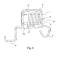
- the yoke (1) is non-magnetic and no fixed magnetic core is attached to said cylinder head (1).
- the displacement of the mobile core 3 is obtained by a location area given a maximum density of magnetic field lines, and to which he is trained. Such a displacement suffices to actuate the striker (6).
- Fig. 8 shows a partially cut-away view, for purposes of clarity, a circuit breaker (15) according to the invention.
- the circuit breaker (15) incorporating a magnetic subassembly according to the invention comprises a modular housing (16) provided with fixing means (17), by example on a support type mounting rail (not shown).
- the circuit breaker (15) has a lever-type actuator tilting device (18) for moving the movable contact (8a) between a opening and closing position (see figure 8) of the electrical connection with the fixed contact (8).
- the striker (6) acts on a mechanical lock (19) known as such, which moves the movable contact (8a) to open the electrical connection with the fixed contact (8).
- This opening leads to the interruption of the circulation of an electric current between the terminals of connection (10) of the circuit breaker and automatically returns the handle (18) in the position corresponding to the separation of the fixed contacts (8) and mobile (8a), thanks to the mechanical lock (19).
- the mechanical lock (19) can be actuated to interrupt the current flow either by the striker (6) or by a bimetallic strip thermal tripping incorporated in the circuit-breaker (15) (no represented in the figures).
Landscapes
- Physics & Mathematics (AREA)
- Electromagnetism (AREA)
- Breakers (AREA)
- Switches That Are Operated By Magnetic Or Electric Fields (AREA)
- Driving Mechanisms And Operating Circuits Of Arc-Extinguishing High-Tension Switches (AREA)
- Hard Magnetic Materials (AREA)
- Air Bags (AREA)
Abstract
Description
- une bobine d'induction
- un noyau magnétique mobile,
- un percuteur se déplaçant avec le noyau mobile,
- et un moyen de rappel élastique sollicité par le déplacement du percuteur.
- la figure 1 est une vue éclatée d'un exemple de réalisation d'un sous-ensemble magnétique conforme à l'invention,
- la figure 2 est une vue en coupe d'un exemple de réalisation d'un sous-ensemble magnétique conforme à l'invention,
- la figure 3 est une vue en éclaté d'un autre exemple de réalisation d'un sous-ensemble magnétique conforme à l'invention,
- la figure 4 est un détail de la figure 3,
- la figure 5 représente le sous-ensemble magnétique de la figure 3 une fois assemblé,
- la figure 6 est un autre exemple de réalisation d'un sous-ensemble magnétique conforme à l'invention,
- la figure 7 est une vue en coupe d'un autre exemple de réalisation, d'un sous-ensemble magnétique conforme à l'invention,
- la figure 8 représente un disjoncteur incorporant un sous-ensemble magnétique conforme à l'invention.
Claims (15)
- Sous-ensemble magnétique pour appareillage électrique modulaire du type disjoncteur, comportant :caractérisé en ce que le noyau mobile (3) est logé dans un support mobile (13), entraíné par le noyau mobile (3) et solidaire du percuteur (6).une bobine d'induction (2),un noyau magnétique mobile (3),un percuteur (6) se déplaçant avec le noyau mobile (3),un moyen de rappel élastique sollicité par le déplacement du percuteur (6),
- Sous-ensemble magnétique selon la revendication 1, caractérisé en ce que le support mobile (13) et le percuteur (6) sont réalisés en une seule pièce.
- Sous-ensemble magnétique selon la revendication 2, caractérisé en ce que le support mobile (13) est une pièce cylindrique se terminant à l'une de ses extrémités par une tige constituant le percuteur (6).
- Sous-ensemble magnétique selon la revendication 2 ou 3,caractérisé en ce que le support mobile (13) est en matière plastique.
- Sous-ensemble magnétique selon l'une des revendications 1 à 4, caractérisé en ce qu'il comporte un moyen de guidage en translation du percuteur (6).
- Sous-ensemble magnétique selon la revendication 5, caractérisé en ce que le moyen de guidage comporte une ouverture (1b) ménagée dans une culasse (1), et traversée par le percuteur (6).
- Sous-ensemble magnétique selon la revendication 5, caractérisé en ce que le moyen de guidage comporte une ouverture (1b), ménagée dans un noyau fixe (3 a) et traversée par le percuteur (6).
- Sous-ensemble magnétique selon les revendications 6 et 7, caractérisé en ce que le noyau fixe (3a) est solidaire de la culasse (1).
- Sous-ensemble magnétique selon la revendication 8 ou 6, caractérisé en ce que la culasse (1) est réalisée en un matériau magnétique, constituant un élément magnétique complémentaire fixe.
- Sous-ensemble magnétique selon la revendication 9, caractérisé en ce qu'une partie de la culasse (1), en regard d'une face polaire (5) du noyau magnétique mobile (3) constitue l'élément magnétique complémentaire fixe.
- Sous-ensemble magnétique selon l'une quelconque des revendications 1 à 10, caractérisé en ce que le moyen de rappel élastique (7a, 7b, 7c) est monté entre le support mobile (13) et la culasse magnétique (1).
- Sous-ensemble magnétique selon la revendication 11, caractérisé en ce que le moyen de rappel élastique est constitué d'une lame flexible (7a).
- Sous-ensemble magnétique selon l'une quelconque des revendications 1 à 12, caractérisé en ce que la bobine d'induction (2) est une bobine à spires disjointes.
- Sous-ensemble magnétique selon l'une quelconque des revendications 1 à 13, caractérisé en ce que les extrémités (2a, 2b) de la bobine (2) d'induction s'écartent tangentiellement des spires de la bobine d'induction (2).
- Disjoncteur électrique comportant :un contact fixe (8) auquel est relié la première extrémité (2 a) de la bobine (2),une borne de connexion (10) au sous-ensemble, à laquelle est reliée la seconde extrémité (2b) de la bobine (2),un sous-ensemble magnétique conforme à l'une quelconque des revendications 1 à 14.
Priority Applications (1)
| Application Number | Priority Date | Filing Date | Title |
|---|---|---|---|
| SI200430099T SI1501112T1 (sl) | 2003-07-22 | 2004-05-28 | Izboljsana magnetna podenota in odklopnik, ki obsega to podenoto |
Applications Claiming Priority (2)
| Application Number | Priority Date | Filing Date | Title |
|---|---|---|---|
| FR0308949A FR2858106B1 (fr) | 2003-07-22 | 2003-07-22 | Sous-ensemble magnetique ameliore et disjoncteur comportant un tel sous-ensemble magnetique |
| FR0308949 | 2003-07-22 |
Publications (2)
| Publication Number | Publication Date |
|---|---|
| EP1501112A1 true EP1501112A1 (fr) | 2005-01-26 |
| EP1501112B1 EP1501112B1 (fr) | 2006-08-09 |
Family
ID=33484684
Family Applications (1)
| Application Number | Title | Priority Date | Filing Date |
|---|---|---|---|
| EP04360055A Expired - Lifetime EP1501112B1 (fr) | 2003-07-22 | 2004-05-28 | Sous-ensemble magnétique amélioré et disjoncteur comportant un tel sous-ensemble magnétique |
Country Status (8)
| Country | Link |
|---|---|
| EP (1) | EP1501112B1 (fr) |
| CN (1) | CN1320580C (fr) |
| AT (1) | ATE336076T1 (fr) |
| BR (1) | BRPI0402801A (fr) |
| DE (1) | DE602004001817T2 (fr) |
| ES (1) | ES2271824T3 (fr) |
| FR (1) | FR2858106B1 (fr) |
| SI (1) | SI1501112T1 (fr) |
Families Citing this family (1)
| Publication number | Priority date | Publication date | Assignee | Title |
|---|---|---|---|---|
| DE102009021771A1 (de) | 2009-05-18 | 2010-11-25 | Abb Ag | Elektromagnetischer Auslöser und Schaltgerät |
Citations (3)
| Publication number | Priority date | Publication date | Assignee | Title |
|---|---|---|---|---|
| EP0515292A1 (fr) * | 1991-05-21 | 1992-11-25 | Schneider Electric Sa | Déclencheur électromagnétique pour un disjoncteur électrique à bas calibres |
| WO1999063564A1 (fr) * | 1998-06-03 | 1999-12-09 | Hager Electro | Sous-ensemble magnetique optimise |
| DE10126854A1 (de) * | 2001-06-01 | 2002-12-19 | Siemens Ag | Magnetjoch eines elektromagnetischen Auslösers |
Family Cites Families (2)
| Publication number | Priority date | Publication date | Assignee | Title |
|---|---|---|---|---|
| US5343178A (en) * | 1993-07-09 | 1994-08-30 | Circuit Breaker Industries Limited | Electric circuit breaker |
| DE19845476B4 (de) * | 1998-10-02 | 2004-08-12 | Aeg Niederspannungstechnik Gmbh & Co Kg | Magnetsystem für Leitungsschutzschalter |
-
2003
- 2003-07-22 FR FR0308949A patent/FR2858106B1/fr not_active Expired - Fee Related
-
2004
- 2004-05-28 ES ES04360055T patent/ES2271824T3/es not_active Expired - Lifetime
- 2004-05-28 AT AT04360055T patent/ATE336076T1/de active
- 2004-05-28 SI SI200430099T patent/SI1501112T1/sl unknown
- 2004-05-28 DE DE602004001817T patent/DE602004001817T2/de not_active Expired - Lifetime
- 2004-05-28 EP EP04360055A patent/EP1501112B1/fr not_active Expired - Lifetime
- 2004-07-20 BR BR0402801-5A patent/BRPI0402801A/pt not_active IP Right Cessation
- 2004-07-22 CN CNB2004100684905A patent/CN1320580C/zh not_active Expired - Fee Related
Patent Citations (3)
| Publication number | Priority date | Publication date | Assignee | Title |
|---|---|---|---|---|
| EP0515292A1 (fr) * | 1991-05-21 | 1992-11-25 | Schneider Electric Sa | Déclencheur électromagnétique pour un disjoncteur électrique à bas calibres |
| WO1999063564A1 (fr) * | 1998-06-03 | 1999-12-09 | Hager Electro | Sous-ensemble magnetique optimise |
| DE10126854A1 (de) * | 2001-06-01 | 2002-12-19 | Siemens Ag | Magnetjoch eines elektromagnetischen Auslösers |
Also Published As
| Publication number | Publication date |
|---|---|
| ATE336076T1 (de) | 2006-09-15 |
| FR2858106B1 (fr) | 2005-09-23 |
| BRPI0402801A (pt) | 2005-05-24 |
| EP1501112B1 (fr) | 2006-08-09 |
| SI1501112T1 (sl) | 2007-02-28 |
| CN1320580C (zh) | 2007-06-06 |
| CN1577687A (zh) | 2005-02-09 |
| DE602004001817D1 (de) | 2006-09-21 |
| FR2858106A1 (fr) | 2005-01-28 |
| ES2271824T3 (es) | 2007-04-16 |
| DE602004001817T2 (de) | 2007-08-16 |
Similar Documents
| Publication | Publication Date | Title |
|---|---|---|
| EP0619591B1 (fr) | Module déclencheur magnéto-thermique | |
| FR2638563A1 (fr) | Dispositif de securite pour appareil de commutation realise par l'assemblage de plusieurs elements modulaires amovibles | |
| FR2573570A1 (fr) | Relais electromagnetique polarise a accrochage magnetique pour un declencheur d'un disjoncteur electrique | |
| EP2678877B1 (fr) | Actionneur magnétothermique. | |
| EP0834895B1 (fr) | Déclencheur électromagnétique pour appareil électrique de protection | |
| EP0143022B1 (fr) | Déclencheur magnétothermique de disjoncteur | |
| EP1501112B1 (fr) | Sous-ensemble magnétique amélioré et disjoncteur comportant un tel sous-ensemble magnétique | |
| EP3699943B1 (fr) | Déclencheur magnétique pour appareil électrique de coupure | |
| WO2019122539A1 (fr) | Appareil électrique de commutation de type modulaire | |
| EP0310469B1 (fr) | Interrupteur de protection à écran de coupure d'arc | |
| EP0027404A1 (fr) | Disjoncteur électrique miniature à boîtier moulé | |
| EP1505619B1 (fr) | Mécanisme de serrure amélioré pour disjoncteur et disjoncteur incorporant un tel mécanisme de serrure | |
| FR2958447A1 (fr) | Declencheur electromagnetique pour appareil electrique interrupteur, appareil electrique interrupteur comportant un tel declencheur | |
| EP0004801B1 (fr) | Disjoncteur à dispositif électromagnétique d'ouverture rapide du contact mobile | |
| EP0926694B1 (fr) | Dispositif de déclenchement magnéto-thermique et disjoncteur équipé de ce dispositif | |
| EP1282146A1 (fr) | Dispositif pour l'extinction d'un arc électrique | |
| EP2973635A1 (fr) | Actionneur magnetothermique | |
| EP1134767B1 (fr) | Dispositif de déclenchement magnétique notamment pour disjoncteur, et appareil de protection électrique comportant un tel dispositif | |
| EP1168402B1 (fr) | Sous-ensemble magnétique pour appareil électrique modulaire d'épaisseur réduite. | |
| EP2750158B1 (fr) | Sous-ensemble magnétique et thermique pour disjoncteur sélectif | |
| FR2722609A1 (fr) | Disjoncteur electrique a actionneur electromagnetique pour calibres eleves | |
| EP0045672B1 (fr) | Disjoncteur miniature à coupure du neutre et de la phase | |
| FR2940515A1 (fr) | Dispositif de telecommande et disjoncteur telecommande equipe d'un tel dispositif | |
| EP3161850B1 (fr) | Déclencheur magnétothermique | |
| FR3020498A1 (fr) | Dispositif a contact mobile sans tresse conductrice. |
Legal Events
| Date | Code | Title | Description |
|---|---|---|---|
| PUAI | Public reference made under article 153(3) epc to a published international application that has entered the european phase |
Free format text: ORIGINAL CODE: 0009012 |
|
| AK | Designated contracting states |
Kind code of ref document: A1 Designated state(s): AT BE BG CH CY CZ DE DK EE ES FI FR GB GR HU IE IT LI LU MC NL PL PT RO SE SI SK TR |
|
| AX | Request for extension of the european patent |
Extension state: AL HR LT LV MK |
|
| 17P | Request for examination filed |
Effective date: 20050325 |
|
| AKX | Designation fees paid |
Designated state(s): AT BE BG CH CY CZ DE DK EE ES FI FR GB GR HU IE IT LI LU MC NL PL PT RO SE SI SK TR |
|
| GRAP | Despatch of communication of intention to grant a patent |
Free format text: ORIGINAL CODE: EPIDOSNIGR1 |
|
| GRAS | Grant fee paid |
Free format text: ORIGINAL CODE: EPIDOSNIGR3 |
|
| GRAA | (expected) grant |
Free format text: ORIGINAL CODE: 0009210 |
|
| AK | Designated contracting states |
Kind code of ref document: B1 Designated state(s): AT BE BG CH CY CZ DE DK EE ES FI FR GB GR HU IE IT LI LU MC NL PL PT RO SE SI SK TR |
|
| PG25 | Lapsed in a contracting state [announced via postgrant information from national office to epo] |
Ref country code: NL Free format text: LAPSE BECAUSE OF FAILURE TO SUBMIT A TRANSLATION OF THE DESCRIPTION OR TO PAY THE FEE WITHIN THE PRESCRIBED TIME-LIMIT Effective date: 20060809 Ref country code: IT Free format text: LAPSE BECAUSE OF FAILURE TO SUBMIT A TRANSLATION OF THE DESCRIPTION OR TO PAY THE FEE WITHIN THE PRESCRIBED TIME-LIMIT;WARNING: LAPSES OF ITALIAN PATENTS WITH EFFECTIVE DATE BEFORE 2007 MAY HAVE OCCURRED AT ANY TIME BEFORE 2007. THE CORRECT EFFECTIVE DATE MAY BE DIFFERENT FROM THE ONE RECORDED. Effective date: 20060809 Ref country code: CZ Free format text: LAPSE BECAUSE OF FAILURE TO SUBMIT A TRANSLATION OF THE DESCRIPTION OR TO PAY THE FEE WITHIN THE PRESCRIBED TIME-LIMIT Effective date: 20060809 Ref country code: SK Free format text: LAPSE BECAUSE OF FAILURE TO SUBMIT A TRANSLATION OF THE DESCRIPTION OR TO PAY THE FEE WITHIN THE PRESCRIBED TIME-LIMIT Effective date: 20060809 Ref country code: RO Free format text: LAPSE BECAUSE OF FAILURE TO SUBMIT A TRANSLATION OF THE DESCRIPTION OR TO PAY THE FEE WITHIN THE PRESCRIBED TIME-LIMIT Effective date: 20060809 Ref country code: IE Free format text: LAPSE BECAUSE OF FAILURE TO SUBMIT A TRANSLATION OF THE DESCRIPTION OR TO PAY THE FEE WITHIN THE PRESCRIBED TIME-LIMIT Effective date: 20060809 Ref country code: PL Free format text: LAPSE BECAUSE OF FAILURE TO SUBMIT A TRANSLATION OF THE DESCRIPTION OR TO PAY THE FEE WITHIN THE PRESCRIBED TIME-LIMIT Effective date: 20060809 Ref country code: FI Free format text: LAPSE BECAUSE OF FAILURE TO SUBMIT A TRANSLATION OF THE DESCRIPTION OR TO PAY THE FEE WITHIN THE PRESCRIBED TIME-LIMIT Effective date: 20060809 |
|
| REG | Reference to a national code |
Ref country code: GB Ref legal event code: FG4D Free format text: NOT ENGLISH |
|
| REG | Reference to a national code |
Ref country code: CH Ref legal event code: EP |
|
| REG | Reference to a national code |
Ref country code: IE Ref legal event code: FG4D Free format text: LANGUAGE OF EP DOCUMENT: FRENCH |
|
| REF | Corresponds to: |
Ref document number: 602004001817 Country of ref document: DE Date of ref document: 20060921 Kind code of ref document: P |
|
| PG25 | Lapsed in a contracting state [announced via postgrant information from national office to epo] |
Ref country code: BG Free format text: LAPSE BECAUSE OF FAILURE TO SUBMIT A TRANSLATION OF THE DESCRIPTION OR TO PAY THE FEE WITHIN THE PRESCRIBED TIME-LIMIT Effective date: 20061109 Ref country code: DK Free format text: LAPSE BECAUSE OF FAILURE TO SUBMIT A TRANSLATION OF THE DESCRIPTION OR TO PAY THE FEE WITHIN THE PRESCRIBED TIME-LIMIT Effective date: 20061109 Ref country code: SE Free format text: LAPSE BECAUSE OF FAILURE TO SUBMIT A TRANSLATION OF THE DESCRIPTION OR TO PAY THE FEE WITHIN THE PRESCRIBED TIME-LIMIT Effective date: 20061109 |
|
| GBT | Gb: translation of ep patent filed (gb section 77(6)(a)/1977) |
Effective date: 20061113 |
|
| PG25 | Lapsed in a contracting state [announced via postgrant information from national office to epo] |
Ref country code: PT Free format text: LAPSE BECAUSE OF FAILURE TO SUBMIT A TRANSLATION OF THE DESCRIPTION OR TO PAY THE FEE WITHIN THE PRESCRIBED TIME-LIMIT Effective date: 20070109 |
|
| NLV1 | Nl: lapsed or annulled due to failure to fulfill the requirements of art. 29p and 29m of the patents act | ||
| REG | Reference to a national code |
Ref country code: IE Ref legal event code: FD4D |
|
| REG | Reference to a national code |
Ref country code: ES Ref legal event code: FG2A Ref document number: 2271824 Country of ref document: ES Kind code of ref document: T3 |
|
| PLBE | No opposition filed within time limit |
Free format text: ORIGINAL CODE: 0009261 |
|
| STAA | Information on the status of an ep patent application or granted ep patent |
Free format text: STATUS: NO OPPOSITION FILED WITHIN TIME LIMIT |
|
| 26N | No opposition filed |
Effective date: 20070510 |
|
| BERE | Be: lapsed |
Owner name: HAGER ELECTRO S.A. Effective date: 20070531 |
|
| PG25 | Lapsed in a contracting state [announced via postgrant information from national office to epo] |
Ref country code: MC Free format text: LAPSE BECAUSE OF NON-PAYMENT OF DUE FEES Effective date: 20070531 |
|
| PG25 | Lapsed in a contracting state [announced via postgrant information from national office to epo] |
Ref country code: BE Free format text: LAPSE BECAUSE OF NON-PAYMENT OF DUE FEES Effective date: 20070531 |
|
| PG25 | Lapsed in a contracting state [announced via postgrant information from national office to epo] |
Ref country code: GR Free format text: LAPSE BECAUSE OF FAILURE TO SUBMIT A TRANSLATION OF THE DESCRIPTION OR TO PAY THE FEE WITHIN THE PRESCRIBED TIME-LIMIT Effective date: 20061110 |
|
| PG25 | Lapsed in a contracting state [announced via postgrant information from national office to epo] |
Ref country code: EE Free format text: LAPSE BECAUSE OF FAILURE TO SUBMIT A TRANSLATION OF THE DESCRIPTION OR TO PAY THE FEE WITHIN THE PRESCRIBED TIME-LIMIT Effective date: 20060809 |
|
| PGRI | Patent reinstated in contracting state [announced from national office to epo] |
Ref country code: IT Effective date: 20080601 |
|
| REG | Reference to a national code |
Ref country code: CH Ref legal event code: PL |
|
| PG25 | Lapsed in a contracting state [announced via postgrant information from national office to epo] |
Ref country code: CH Free format text: LAPSE BECAUSE OF NON-PAYMENT OF DUE FEES Effective date: 20080531 Ref country code: LI Free format text: LAPSE BECAUSE OF NON-PAYMENT OF DUE FEES Effective date: 20080531 |
|
| PG25 | Lapsed in a contracting state [announced via postgrant information from national office to epo] |
Ref country code: LU Free format text: LAPSE BECAUSE OF NON-PAYMENT OF DUE FEES Effective date: 20070528 Ref country code: CY Free format text: LAPSE BECAUSE OF FAILURE TO SUBMIT A TRANSLATION OF THE DESCRIPTION OR TO PAY THE FEE WITHIN THE PRESCRIBED TIME-LIMIT Effective date: 20060809 |
|
| PG25 | Lapsed in a contracting state [announced via postgrant information from national office to epo] |
Ref country code: HU Free format text: LAPSE BECAUSE OF FAILURE TO SUBMIT A TRANSLATION OF THE DESCRIPTION OR TO PAY THE FEE WITHIN THE PRESCRIBED TIME-LIMIT Effective date: 20070210 Ref country code: TR Free format text: LAPSE BECAUSE OF FAILURE TO SUBMIT A TRANSLATION OF THE DESCRIPTION OR TO PAY THE FEE WITHIN THE PRESCRIBED TIME-LIMIT Effective date: 20060809 |
|
| REG | Reference to a national code |
Ref country code: FR Ref legal event code: PLFP Year of fee payment: 13 |
|
| REG | Reference to a national code |
Ref country code: FR Ref legal event code: PLFP Year of fee payment: 14 |
|
| PGFP | Annual fee paid to national office [announced via postgrant information from national office to epo] |
Ref country code: FR Payment date: 20170511 Year of fee payment: 17 |
|
| PGFP | Annual fee paid to national office [announced via postgrant information from national office to epo] |
Ref country code: SI Payment date: 20170509 Year of fee payment: 14 |
|
| PG25 | Lapsed in a contracting state [announced via postgrant information from national office to epo] |
Ref country code: SI Free format text: LAPSE BECAUSE OF NON-PAYMENT OF DUE FEES Effective date: 20180529 |
|
| REG | Reference to a national code |
Ref country code: SI Ref legal event code: KO00 Effective date: 20190108 |
|
| PG25 | Lapsed in a contracting state [announced via postgrant information from national office to epo] |
Ref country code: FR Free format text: LAPSE BECAUSE OF NON-PAYMENT OF DUE FEES Effective date: 20180531 |
|
| PGFP | Annual fee paid to national office [announced via postgrant information from national office to epo] |
Ref country code: IT Payment date: 20210524 Year of fee payment: 18 Ref country code: DE Payment date: 20210527 Year of fee payment: 18 |
|
| PGFP | Annual fee paid to national office [announced via postgrant information from national office to epo] |
Ref country code: AT Payment date: 20210504 Year of fee payment: 18 Ref country code: GB Payment date: 20210527 Year of fee payment: 18 Ref country code: ES Payment date: 20210601 Year of fee payment: 18 |
|
| REG | Reference to a national code |
Ref country code: DE Ref legal event code: R119 Ref document number: 602004001817 Country of ref document: DE |
|
| REG | Reference to a national code |
Ref country code: AT Ref legal event code: MM01 Ref document number: 336076 Country of ref document: AT Kind code of ref document: T Effective date: 20220528 |
|
| GBPC | Gb: european patent ceased through non-payment of renewal fee |
Effective date: 20220528 |
|
| PG25 | Lapsed in a contracting state [announced via postgrant information from national office to epo] |
Ref country code: AT Free format text: LAPSE BECAUSE OF NON-PAYMENT OF DUE FEES Effective date: 20220528 |
|
| PG25 | Lapsed in a contracting state [announced via postgrant information from national office to epo] |
Ref country code: GB Free format text: LAPSE BECAUSE OF NON-PAYMENT OF DUE FEES Effective date: 20220528 Ref country code: DE Free format text: LAPSE BECAUSE OF NON-PAYMENT OF DUE FEES Effective date: 20221201 |
|
| REG | Reference to a national code |
Ref country code: ES Ref legal event code: FD2A Effective date: 20230703 |
|
| PG25 | Lapsed in a contracting state [announced via postgrant information from national office to epo] |
Ref country code: IT Free format text: LAPSE BECAUSE OF FAILURE TO SUBMIT A TRANSLATION OF THE DESCRIPTION OR TO PAY THE FEE WITHIN THE PRESCRIBED TIME-LIMIT Effective date: 20220528 Ref country code: ES Free format text: LAPSE BECAUSE OF NON-PAYMENT OF DUE FEES Effective date: 20220529 |