EP1501149A2 - Système de pile à combustible - Google Patents
Système de pile à combustible Download PDFInfo
- Publication number
- EP1501149A2 EP1501149A2 EP04017367A EP04017367A EP1501149A2 EP 1501149 A2 EP1501149 A2 EP 1501149A2 EP 04017367 A EP04017367 A EP 04017367A EP 04017367 A EP04017367 A EP 04017367A EP 1501149 A2 EP1501149 A2 EP 1501149A2
- Authority
- EP
- European Patent Office
- Prior art keywords
- fuel cell
- discharged
- burner
- hydrogen
- heat exchanger
- Prior art date
- Legal status (The legal status is an assumption and is not a legal conclusion. Google has not performed a legal analysis and makes no representation as to the accuracy of the status listed.)
- Withdrawn
Links
Images

Classifications
-
- F—MECHANICAL ENGINEERING; LIGHTING; HEATING; WEAPONS; BLASTING
- F23—COMBUSTION APPARATUS; COMBUSTION PROCESSES
- F23C—METHODS OR APPARATUS FOR COMBUSTION USING FLUID FUEL OR SOLID FUEL SUSPENDED IN A CARRIER GAS OR AIR
- F23C13/00—Apparatus in which combustion takes place in the presence of catalytic material
-
- H—ELECTRICITY
- H01—ELECTRIC ELEMENTS
- H01M—PROCESSES OR MEANS, e.g. BATTERIES, FOR THE DIRECT CONVERSION OF CHEMICAL ENERGY INTO ELECTRICAL ENERGY
- H01M8/00—Fuel cells; Manufacture thereof
- H01M8/04—Auxiliary arrangements, e.g. for control of pressure or for circulation of fluids
- H01M8/04007—Auxiliary arrangements, e.g. for control of pressure or for circulation of fluids related to heat exchange
-
- H—ELECTRICITY
- H01—ELECTRIC ELEMENTS
- H01M—PROCESSES OR MEANS, e.g. BATTERIES, FOR THE DIRECT CONVERSION OF CHEMICAL ENERGY INTO ELECTRICAL ENERGY
- H01M8/00—Fuel cells; Manufacture thereof
- H01M8/04—Auxiliary arrangements, e.g. for control of pressure or for circulation of fluids
- H01M8/04007—Auxiliary arrangements, e.g. for control of pressure or for circulation of fluids related to heat exchange
- H01M8/04014—Heat exchange using gaseous fluids; Heat exchange by combustion of reactants
- H01M8/04022—Heating by combustion
-
- H—ELECTRICITY
- H01—ELECTRIC ELEMENTS
- H01M—PROCESSES OR MEANS, e.g. BATTERIES, FOR THE DIRECT CONVERSION OF CHEMICAL ENERGY INTO ELECTRICAL ENERGY
- H01M8/00—Fuel cells; Manufacture thereof
- H01M8/04—Auxiliary arrangements, e.g. for control of pressure or for circulation of fluids
- H01M8/04082—Arrangements for control of reactant parameters, e.g. pressure or concentration
- H01M8/04089—Arrangements for control of reactant parameters, e.g. pressure or concentration of gaseous reactants
- H01M8/04111—Arrangements for control of reactant parameters, e.g. pressure or concentration of gaseous reactants using a compressor turbine assembly
-
- F—MECHANICAL ENGINEERING; LIGHTING; HEATING; WEAPONS; BLASTING
- F23—COMBUSTION APPARATUS; COMBUSTION PROCESSES
- F23C—METHODS OR APPARATUS FOR COMBUSTION USING FLUID FUEL OR SOLID FUEL SUSPENDED IN A CARRIER GAS OR AIR
- F23C2900/00—Special features of, or arrangements for combustion apparatus using fluid fuels or solid fuels suspended in air; Combustion processes therefor
- F23C2900/9901—Combustion process using hydrogen, hydrogen peroxide water or brown gas as fuel
-
- H—ELECTRICITY
- H01—ELECTRIC ELEMENTS
- H01M—PROCESSES OR MEANS, e.g. BATTERIES, FOR THE DIRECT CONVERSION OF CHEMICAL ENERGY INTO ELECTRICAL ENERGY
- H01M8/00—Fuel cells; Manufacture thereof
- H01M8/10—Fuel cells with solid electrolytes
- H01M2008/1095—Fuel cells with polymeric electrolytes
-
- Y—GENERAL TAGGING OF NEW TECHNOLOGICAL DEVELOPMENTS; GENERAL TAGGING OF CROSS-SECTIONAL TECHNOLOGIES SPANNING OVER SEVERAL SECTIONS OF THE IPC; TECHNICAL SUBJECTS COVERED BY FORMER USPC CROSS-REFERENCE ART COLLECTIONS [XRACs] AND DIGESTS
- Y02—TECHNOLOGIES OR APPLICATIONS FOR MITIGATION OR ADAPTATION AGAINST CLIMATE CHANGE
- Y02E—REDUCTION OF GREENHOUSE GAS [GHG] EMISSIONS, RELATED TO ENERGY GENERATION, TRANSMISSION OR DISTRIBUTION
- Y02E60/00—Enabling technologies; Technologies with a potential or indirect contribution to GHG emissions mitigation
- Y02E60/30—Hydrogen technology
- Y02E60/50—Fuel cells
Definitions
- the fuel cell system currently described by JP2002-216815A is equipped with a humidifier for humidifying a high polymer electrolyte film used for a solid high polymer type fuel cell. While the solid high polymer type fuel cell using the solid high polymer electrolyte has a low temperature of operation and handling is easy, the high polymer electrolyte film has the characteristic of not fully demonstrating hydrogen ion conductivity, if not fully humidified.
- each of a hydrogen supply system which supplies hydrogen to the fuel cell, and an oxygen supply system which supplies oxygen to the fuel cell provides the humidifier which uses a water penetration type hollow fiber, and moisture is moved to hydrogen supply gas from discharged hydrogen gas and to oxygen supply gas from discharged oxygen gas, and hydrogen supply gas and oxygen supply gas are humidified. Furthermore, a burner bums the discharged hydrogen gas and the discharged oxygen gas, and discharges the discharged hydrogen gas and oxygen gas as steam.
- the burner when the temperature of the discharged oxygen gas in the period wherein hydrogen gas is not discharged is lower than the catalyst activity temperature of the burner, the burner is cooled by the discharged oxygen gas, the activity of a combustion catalyst may be unable to be demonstrated and the hydrogen contained in the discharged hydrogen gas may be unable to be fully burned.
- catalyst temperature is lower than catalyst activity temperature when starting the supply of hydrogen gas, the hydrogen contained in hydrogen gas may be unable to fully be burned.
- the oxygen gas discharged is cooled with the oxygen discharge system to a burner and the burner, in starting of a fuel cell at the freezing point, the condensation of moisture contained in the oxygen gas discharged may take place, and the fall of the ignition characteristic of a burner may occur.
- the present invention provides a fuel cell system comprising a fuel cell which generates electrical power by causing hydrogen and oxygen to react; a compressor which compresses oxidizer gas supplied to a fuel cell stack; a catalyst burner with which a combustion catalyst burns mixed gas of discharged hydrogen gas which is intermittently discharged from the fuel cell stack and discharged oxygen gas continuously discharged from the fuel cell stack; and a heating device which generates heat in order to raise the catalyst temperature of a catalyst burner.
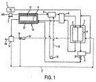
- FIG. 1 is a schematic diagram of a fuel cell system according to a first embodiment of this invention.
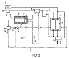
- FIG. 2 is a schematic diagram of a fuel cell system according to a second embodiment of this invention.
- FIG. 3 is a schematic diagram of a fuel cell system according to a third embodiment of this invention.
- Fig. 1 shows the composition of the first embodiment of the operation of the fuel cell system of this invention.
- This fuel cell system provides a catalyst burner which burns the discharged-gas discharged from a fuel cell stack with a heating device to raise catalyst temperature, for example, and is a suitable fuel cell system for fuel cell vehicles.
- a fuel cell system is comprised of a hydrogen supply device 1 with which a fuel cell system supplies hydrogen as fuel gas, a compressor 2 which supplies air as oxidizer gas, and a fuel cell stack 3 which has an anode 4 and cathode 5, circulation equipment 6 of the discharged hydrogen which is discharged from anode 4 and an after-cooler 8 which cools the air compressed by the compressor, a humidifier 9 which humidifies the moisture of discharged oxygen gas to the air cooled by the after-cooler 8, a burner 10 which bums mixed gas of the discharged hydrogen gas intermittently discharged from anode 4, and the discharged oxygen gas discharged from cathode 5, a heat exchanger 14 for defrosting, and cooling-water passage 15 for providing cooling water which cools an after-cooler 8, a cooling-water pump 16 which makes the cooling-water passage 15 circulate through cooling water, and a cooling-water passage 17 for providing cooling water which cools the fuel cell stack 3.
- a hydrogen supply device 1 with which a fuel cell system supplies hydrogen as fuel gas
- the cooling-water passage 17 is equipped with cooling-water pump 18 provided to circulate through cooling water, a three-way valve 19 which switches a the cooling-water passage 17, the exhaust piping 24, and the purging valve 30 which discharges the discharged hydrogen gas from circulation equipment 6 to a burner 10.
- the burner 10 is provided with a combustion catalyst 12 which burns the mixed gas mixed with a mixer 11 which mixes the discharged oxygen gas dehumidified via the humidifier 9, and the discharged hydrogen gas discharged from the purging valve 30, and a heat exchanger 37 in the burner for heating the combustion catalyst 12.
- the cooling system (PM-cooling system) which cools the after-cooler 8 and the cooling system (FC-cooling system) which cools the fuel cell stack 3 shall be separated, and heat shall be radiated out of a system in the heat of the cooling water of each system through a radiator which is not illustrated, respectively.
- the PM-cooling system also cools power modules, such as an inverter which charges direct-current electric power which the fuel cell stack generate to power for a vehicles drive ,which is not illustrated.
- power modules such as an inverter which charges direct-current electric power which the fuel cell stack generate to power for a vehicles drive ,which is not illustrated.
- the oxygen gas is pressurized to a pressure required for the reaction of the fuel cell stack 3 in compressor 2.
- the pressurized supply oxygen is cooled to a temperature required for the reaction of the fuel cell stack 3 by the after-cooler 8.
- the whole quantity of the discharged hydrogen gas circulates with circulation equipment 6.
- the discharged hydrogen gas which is circulated joins supply hydrogen and is again supplied to the anode 4.
- the discharged hydrogen gas is purged once to the burner 10 by operation of the purging valve 30 at a rate from several seconds to dozens of seconds according to hydrogen concentration etc, and is exhausted outside by the exhaust piping24.
- the discharged oxygen gas is exhausted outside from the exhaust piping 24 via a burner 10 via the humidifier 9 which humidifies the supply air to fuel cell stack 3.
- a burner 10 provides a mixer 11 which mixes the discharged hydrogen gas which is intermittently supplied from the circulation equipment 6 and the discharged oxygen gas, and forms uniform mixed gas, the combustion catalyst 12 which includes an oxidization catalyst and burns the mixed gas, and a heat exchanger 37 in the burner prepared in the perimeter.
- the combustion gas generated with the burner 10 is exhausted from the exhaust piping 24 via the heat exchanger 14 for defrosting.
- the discharged oxygen gas is discharged from the cathode 5 of fuel cell stack 3 to a humidifier 9.
- the discharged oxygen gas can lower its relative humidity by passing moisture to the supply air of comparatively low humidity discharged from the after-cooler 8 within a humidifier 9.
- the hydrogen contained in the discharged hydrogen gas when purging and intermittently supplied to the burner 10 from circulation equipment 6 can burn promptly.
- the air breathed out from before compressor 2 is cooled by the heat exchanger 37 in the burner supplying the air to the after-cooler 8.
- the after-cooler 8 can be miniaturized and the energy consumed by the compressor 2 compressing supply air can be used effectively as thermal energy. Furthermore, since it is not necessary to use electric formula heating device, such as an electric heater, economical efficiency will improve.
- Fig. 2 shows the composition of the second embodiment of the operation of the fuel cell system of this invention.
- the supply of cooling water (PM-cooling system) heated in the after-cooler 8 is used to cause a temperature rise in the heat exchanger 37 in the burner 10, which differs from the first embodiment wherein hot air compressed by the compressor 2 , is used to cause a temperature rise in to the heat exchanger 37 in the burner 10.
- Other composition and actions are the same as that of the first embodiment.
- the discharged hydrogen gas from the cathode 5 of fuel cell stack 3 is supplied to the burner 10 through the humidifier 9 like the first embodiment.
- the discharged hydrogen gas is purged once to the burner 10 by operation of the purging valve 30 at a rate from several seconds to dozens of seconds according to hydrogen concentration etc.
- the compressed hot air to which it is pressurized by the compressor 2 rise is cooled by the after-cooler 8 to a temperature required for the reaction of fuel cell stack 3.
- the cooling water of the PM-cooling system is circulated to the heat exchanger 37 in the burner 10, and heat is regularly given to the combustion catalyst 12, so that it is kept warm, and discharged oxygen gas is warmed.
- the thermal energy of the compressor 2 can be used effectively.
- heat exchange is performed between the hot supply air pressurized by the compressor 2, and the discharged oxygen gas or the combustion catalyst 12. That is, by heat exchange between gas and gas or between gas and a solid, the discharged oxygen gas and the combustion catalyst 12 are warmed and kept warm.
- heat exchange is performed between cooling water of the PM-cooling system and the discharged oxygen gas or the combustion catalyst 12. That is, by heat exchange between liquid and gas or between liquid and a solid, the discharged oxygen gas and the combustion catalyst 12 are warmed and kept warm.
- the efficiency of heat exchange can increase, and the heat exchanger 37 in the burner10 can be miniaturized and vehicle weight and arrangement can be improved.
- Fig. 3 shows the composition of the third embodiment of the operation of the fuel cell system of this invention.
- hot water is supplied to the heat exchanger 37 from either the PM-cooling system (PM-cooling water) which passed the after-cooler 8, or the cooling water (FC-cooling water) of the FC-cooling system which passed fuel cell stack 3, which differs from the second embodiment which supplies the cooling water of the PM-cooling system which passed the after-cooler 8 to the heat exchanger 37 in the burner 10.
- a fuel cell system is comprised of hydrogen supply device 1 with which a fuel cell system supplies hydrogen as fuel gas, a compressor 2 which supplies air as oxidizer gas, and a fuel cell stack 3 which has an anode 4 and cathode 5, circulation equipment 6 of the discharged hydrogen which is discharged from anode 4, the after-cooler 8 which cools the air compressed by the compressor, a humidifier 9 which humidifies the moisture of discharged oxygen gas to the air cooled by the after-cooler 8, a burner 10 which bums the mixed gas of the discharged hydrogen gas intermittently discharged from anode 4, and the discharged oxygen gas discharged from cathode 5, and the cooling-water passage 15 for providing cooling water which cools an after-cooler 8, a cooling-water pump 16 which makes the cooling-water passage 15 circulate through cooling water, and the cooling-water passage 17 for providing cooling water which cools the fuel cell stack 3.
- hydrogen supply device 1 with which a fuel cell system supplies hydrogen as fuel gas
- a compressor 2 which supplies air as oxidizer gas
- the cooling-water passage 17 is equipped with a cooling-water pump 18 made to circulate through cooling water.
- a three-way valve 19 switches the cooling-water passage 17 to the burner heat exchanger 37 or to a bypass passage 40.
- a purging valve 30 discharges the discharged hydrogen gas from circulation equipment 6 to the burner 10 and then to exhaust piping 24.
- a three-way valve 34 which supplies PM-cooling water which comes out of the after-cooler 8 to the burner heat exchanger 37 or to a bypass passage 38.
- a three-way valve 36 circulates the PM-cooling water or the FC-cooling water from the burner heat exchanger 37 is returned to the cooling-water pump 16, or it returns to fuel cell stack 3.
- the burner 10 is provided with the combustion catalyst 12 which burns the mixed gas mixed with the mixer 11 which mixes the discharged oxygen gas dehumidified via the humidifier 9 and the discharged hydrogen gas discharged from the purging valve 30, and the heat exchanger 37 need the combustion catalyst 12.
- the cooling water of the PM-cooling system is a refrigerant that circulates by the after-cooler 8, which cools the supply air (that is pressurized and heated) to a temperature required for the reaction of the fuel cell stack 3.
- the FC-cooling water is a refrigerant used for cooling and temperature adjustment of the fuel cell stack 3. Moreover, the FC-cooling water is used also for defrosting when the fuel cell stack 3 freezes.
- This embodiment is constituted so that it can be made to switch between providing PM-cooling water and FC-cooling water to the heat exchanger 37 in a burner if needed as a refrigerant by forming the three-way valve 34 which adjusts the flow of PM-cooling water and the bypass passage 38 on the cooling-water passage 15 of PM-cooling water, the three-way valve 19 which adjusts the flow of FC-cooling water and the bypass passage 40 on the cooling-water passage 17 of FC-cooling water, and the three-way valve 36 in the exit of the heat exchanger 37 in the burner 10.
- FC-cooling water circulates to the heat exchanger 37, and the discharged oxygen gas and the combustion catalyst 12 are warmed. Under the present circumstances, PM-cooling water flows from the three-way valve 34 to the bypass passage 38.
- the fuel cell stack 3 does not generate power when frozen, and is drying both the air and hydrogen that are supplied to the burner 10. Therefore, the temperature of the combustion catalyst 12 can rise and the combustion catalyst 12 activates comparatively easily at an electric heater etc. In this case, the atmosphere is at the freezing point. Since supply air is still low temperature comparatively even after pressurization by the compressor 2 the PM-cooling water is maintained at low temperature, and the PM-cooling water does not need to circulate to the heat exchanger 37 in the burner 10. Thus, the heat exchanger 37 in the burner 10 can perform as a heat exchanger for defrosting switching between providing PM-cooling water and FC-cooling water to the heat exchanger 37 in the burner 10 as needed. Therefore, according to this embodiment, the heat exchanger 14 for defrosting in the 1st and the 2nd embodiment is omissible from a fuel cell system.
Landscapes
- Engineering & Computer Science (AREA)
- Chemical & Material Sciences (AREA)
- Chemical Kinetics & Catalysis (AREA)
- Life Sciences & Earth Sciences (AREA)
- Combustion & Propulsion (AREA)
- Manufacturing & Machinery (AREA)
- Sustainable Development (AREA)
- Sustainable Energy (AREA)
- Electrochemistry (AREA)
- General Chemical & Material Sciences (AREA)
- Mechanical Engineering (AREA)
- General Engineering & Computer Science (AREA)
- Fuel Cell (AREA)
Applications Claiming Priority (2)
| Application Number | Priority Date | Filing Date | Title |
|---|---|---|---|
| JP2003277657 | 2003-07-22 | ||
| JP2003277657A JP2005044630A (ja) | 2003-07-22 | 2003-07-22 | 燃料電池システム |
Publications (2)
| Publication Number | Publication Date |
|---|---|
| EP1501149A2 true EP1501149A2 (fr) | 2005-01-26 |
| EP1501149A3 EP1501149A3 (fr) | 2005-12-14 |
Family
ID=33487685
Family Applications (1)
| Application Number | Title | Priority Date | Filing Date |
|---|---|---|---|
| EP04017367A Withdrawn EP1501149A3 (fr) | 2003-07-22 | 2004-07-22 | Système de pile à combustible |
Country Status (3)
| Country | Link |
|---|---|
| US (1) | US20050019633A1 (fr) |
| EP (1) | EP1501149A3 (fr) |
| JP (1) | JP2005044630A (fr) |
Cited By (1)
| Publication number | Priority date | Publication date | Assignee | Title |
|---|---|---|---|---|
| EP3410525A1 (fr) * | 2017-06-01 | 2018-12-05 | Hamilton Sundstrand Corporation | Oxydant catalytique chauffé pour un environnement humide clos |
Families Citing this family (12)
| Publication number | Priority date | Publication date | Assignee | Title |
|---|---|---|---|---|
| US8139598B2 (en) * | 2005-03-21 | 2012-03-20 | Telefonaktiebolaget L M Ericsson (Publ) | Automatic QoS configuration |
| JP5021236B2 (ja) * | 2006-05-18 | 2012-09-05 | 本田技研工業株式会社 | 燃料電池システム |
| KR100748547B1 (ko) | 2006-05-25 | 2007-08-14 | 엘지전자 주식회사 | 열교환모듈 및 이를 구비한 연료전지시스템 |
| KR101061448B1 (ko) | 2008-11-11 | 2011-09-02 | 한국전력공사 | 고체 산화물 연료전지 발전시스템용 일체형 열교환 장치 |
| DE102009009673A1 (de) | 2009-02-19 | 2010-08-26 | Daimler Ag | Brennstoffzellensystem mit wenigstens einer Brennstoffzelle |
| DE102009009674A1 (de) * | 2009-02-19 | 2010-08-26 | Daimler Ag | Brennstoffzellensystem mit wenigstens einer Brennstoffzelle |
| DE102009009675A1 (de) * | 2009-02-19 | 2010-08-26 | Daimler Ag | Brennstoffzellensystem mit wenigstens einer Brennstoffzelle |
| DE102010008205A1 (de) * | 2010-02-17 | 2011-08-18 | Daimler AG, 70327 | Brennstoffzellensystem mit wenigstens einer Brennstoffzelle |
| DE112013001164T5 (de) * | 2012-02-27 | 2014-11-06 | Dana Canada Corporation | Verfahren und System zum Kühlen von Ladeluft für eine Brennstoffzelle und Drei-Fluidladeluftkühler |
| DE202015106976U1 (de) * | 2015-12-21 | 2017-03-22 | Reinz-Dichtungs-Gmbh | Gaszu- und -abführsystem |
| CN116264297A (zh) * | 2021-12-14 | 2023-06-16 | 中国科学院大连化学物理研究所 | 一种低气压氢空燃料电池系统的低温启动方法 |
| JP2023178814A (ja) * | 2022-06-06 | 2023-12-18 | 日産自動車株式会社 | 燃料電池システムの制御方法、及び燃料電池システム |
Family Cites Families (6)
| Publication number | Priority date | Publication date | Assignee | Title |
|---|---|---|---|---|
| DE19755116C1 (de) * | 1997-12-11 | 1999-03-04 | Dbb Fuel Cell Engines Gmbh | PEM-Brennstoffzellensystem sowie Verfahren zum Betreiben eines PEM-Brennstoffzellensystems |
| US6916564B2 (en) * | 2000-05-31 | 2005-07-12 | Nuvera Fuel Cells, Inc. | High-efficiency fuel cell power system with power generating expander |
| EP1179709B1 (fr) * | 2000-08-09 | 2005-12-14 | Calsonic Kansei Corporation | Système de chauffage par combustion d'hydrogène |
| JP4611513B2 (ja) * | 2000-12-22 | 2011-01-12 | 本田技研工業株式会社 | 燃料電池システム |
| US6612830B2 (en) * | 2001-08-10 | 2003-09-02 | Precision Combustion, Inc. | Anode gas burner for inert gas generation, method and apparatus |
| DE10139608B4 (de) * | 2001-08-11 | 2007-05-16 | Nucellsys Gmbh | Brennstoffzellenanlage mit einem Gaserzeugungssystem und einem Brennstoffzellensystem und deren Verwendung |
-
2003
- 2003-07-22 JP JP2003277657A patent/JP2005044630A/ja active Pending
-
2004
- 2004-07-19 US US10/893,249 patent/US20050019633A1/en not_active Abandoned
- 2004-07-22 EP EP04017367A patent/EP1501149A3/fr not_active Withdrawn
Cited By (2)
| Publication number | Priority date | Publication date | Assignee | Title |
|---|---|---|---|---|
| EP3410525A1 (fr) * | 2017-06-01 | 2018-12-05 | Hamilton Sundstrand Corporation | Oxydant catalytique chauffé pour un environnement humide clos |
| US10403918B2 (en) | 2017-06-01 | 2019-09-03 | Hamilton Sundstrand Corporation | Heated catalytic oxidizer for an enclosed humid environment |
Also Published As
| Publication number | Publication date |
|---|---|
| EP1501149A3 (fr) | 2005-12-14 |
| JP2005044630A (ja) | 2005-02-17 |
| US20050019633A1 (en) | 2005-01-27 |
Similar Documents
| Publication | Publication Date | Title |
|---|---|---|
| CN110957503B (zh) | 一种燃料电池低温启动的空气加热回流系统及控制方法 | |
| KR100943626B1 (ko) | 저장 중에 연료 전지 동력 장치 내의 물의 동결을방지하기 위한 방법 및 장치 | |
| US6673481B1 (en) | Initiating operation of an electric vehicle or other load powered by a fuel cell at sub-freezing temperature | |
| US6699612B2 (en) | Fuel cell power plant having a reduced free water volume | |
| EP1501149A2 (fr) | Système de pile à combustible | |
| US8298713B2 (en) | Thermally integrated fuel cell humidifier for rapid warm-up | |
| KR102387889B1 (ko) | 차량용 연료전지 시스템 | |
| GB2495053A (en) | Fuel cell system | |
| US10135081B2 (en) | Warming feature for aircraft fuel cells | |
| US20050008910A1 (en) | Fuel cell system | |
| JP2007522623A (ja) | 燃料電池システムのための細分割冷却回路 | |
| US20040229099A1 (en) | Apparatus and method for internal stack temperature control | |
| US7998633B2 (en) | Fuel cell system | |
| CN102763257B (zh) | 具有至少一个燃料电池的燃料电池系统 | |
| JP2005294118A (ja) | 燃料電池システム及び燃料電池車両 | |
| JP2015153563A (ja) | 燃料電池システム | |
| KR101237212B1 (ko) | 연료전지 냉각시스템 | |
| JP2005322527A (ja) | 燃料電池システム | |
| JP4501165B2 (ja) | 車輌用燃料電池システム | |
| JP3815303B2 (ja) | 燃料電池システム | |
| JP3873763B2 (ja) | 燃料電池システム | |
| JP2009238628A (ja) | 燃料電池システム | |
| JP2006164681A (ja) | 燃料電池用温度調節装置 | |
| JP2006185748A (ja) | 燃料電池パワープラントおよび燃料電池パワープラント部品の支持構造 | |
| JP2006302678A (ja) | 燃料電池システム |
Legal Events
| Date | Code | Title | Description |
|---|---|---|---|
| PUAI | Public reference made under article 153(3) epc to a published international application that has entered the european phase |
Free format text: ORIGINAL CODE: 0009012 |
|
| 17P | Request for examination filed |
Effective date: 20040722 |
|
| AK | Designated contracting states |
Kind code of ref document: A2 Designated state(s): AT BE BG CH CY CZ DE DK EE ES FI FR GB GR HU IE IT LI LU MC NL PL PT RO SE SI SK TR |
|
| AX | Request for extension of the european patent |
Extension state: AL HR LT LV MK |
|
| PUAL | Search report despatched |
Free format text: ORIGINAL CODE: 0009013 |
|
| STAA | Information on the status of an ep patent application or granted ep patent |
Free format text: STATUS: THE APPLICATION HAS BEEN WITHDRAWN |
|
| AK | Designated contracting states |
Kind code of ref document: A3 Designated state(s): AT BE BG CH CY CZ DE DK EE ES FI FR GB GR HU IE IT LI LU MC NL PL PT RO SE SI SK TR |
|
| AX | Request for extension of the european patent |
Extension state: AL HR LT LV MK |
|
| RIC1 | Information provided on ipc code assigned before grant |
Ipc: 7F 23C 11/00 B Ipc: 7H 01M 8/06 B Ipc: 7H 01M 8/04 B Ipc: 7H 01M 8/02 A |
|
| 18W | Application withdrawn |
Effective date: 20051114 |